EP0360776B1 - A loading device - Google Patents
A loading device Download PDFInfo
- Publication number
- EP0360776B1 EP0360776B1 EP89850309A EP89850309A EP0360776B1 EP 0360776 B1 EP0360776 B1 EP 0360776B1 EP 89850309 A EP89850309 A EP 89850309A EP 89850309 A EP89850309 A EP 89850309A EP 0360776 B1 EP0360776 B1 EP 0360776B1
- Authority
- EP
- European Patent Office
- Prior art keywords
- projectile
- magazine
- weapon
- loading
- cartridge
- Prior art date
- Legal status (The legal status is an assumption and is not a legal conclusion. Google has not performed a legal analysis and makes no representation as to the accuracy of the status listed.)
- Expired - Lifetime
Links
- 230000003993 interaction Effects 0.000 claims abstract description 14
- 238000010304 firing Methods 0.000 claims abstract description 12
- 239000004429 Calibre Substances 0.000 claims abstract description 9
- 241001417527 Pempheridae Species 0.000 claims abstract description 4
- 230000014759 maintenance of location Effects 0.000 claims description 13
- 238000006073 displacement reaction Methods 0.000 claims description 10
- 230000003028 elevating effect Effects 0.000 claims description 6
- 238000010408 sweeping Methods 0.000 claims description 4
- 230000000694 effects Effects 0.000 claims description 2
- 230000006978 adaptation Effects 0.000 claims 1
- 230000004913 activation Effects 0.000 description 5
- 230000004044 response Effects 0.000 description 4
- 238000010276 construction Methods 0.000 description 3
- 239000012190 activator Substances 0.000 description 2
- 238000000605 extraction Methods 0.000 description 2
- 230000007246 mechanism Effects 0.000 description 2
- 238000013539 mentalization-based treatment Methods 0.000 description 2
- 238000000034 method Methods 0.000 description 2
- 230000001960 triggered effect Effects 0.000 description 2
- 208000027418 Wounds and injury Diseases 0.000 description 1
- 239000006096 absorbing agent Substances 0.000 description 1
- 230000006378 damage Effects 0.000 description 1
- 208000014674 injury Diseases 0.000 description 1
- 238000004519 manufacturing process Methods 0.000 description 1
- 230000008569 process Effects 0.000 description 1
- 239000003380 propellant Substances 0.000 description 1
- 230000035939 shock Effects 0.000 description 1
Images


Classifications
-
- F—MECHANICAL ENGINEERING; LIGHTING; HEATING; WEAPONS; BLASTING
- F41—WEAPONS
- F41A—FUNCTIONAL FEATURES OR DETAILS COMMON TO BOTH SMALLARMS AND ORDNANCE, e.g. CANNONS; MOUNTINGS FOR SMALLARMS OR ORDNANCE
- F41A9/00—Feeding or loading of ammunition; Magazines; Guiding means for the extracting of cartridges
- F41A9/01—Feeding of unbelted ammunition
- F41A9/06—Feeding of unbelted ammunition using cyclically moving conveyors, i.e. conveyors having ammunition pusher or carrier elements which are emptied or disengaged from the ammunition during the return stroke
- F41A9/09—Movable ammunition carriers or loading trays, e.g. for feeding from magazines
- F41A9/10—Movable ammunition carriers or loading trays, e.g. for feeding from magazines pivoting or swinging
- F41A9/11—Movable ammunition carriers or loading trays, e.g. for feeding from magazines pivoting or swinging in a horizontal plane
-
- F—MECHANICAL ENGINEERING; LIGHTING; HEATING; WEAPONS; BLASTING
- F41—WEAPONS
- F41A—FUNCTIONAL FEATURES OR DETAILS COMMON TO BOTH SMALLARMS AND ORDNANCE, e.g. CANNONS; MOUNTINGS FOR SMALLARMS OR ORDNANCE
- F41A9/00—Feeding or loading of ammunition; Magazines; Guiding means for the extracting of cartridges
- F41A9/37—Feeding two or more kinds of ammunition to the same gun; Feeding from two sides
- F41A9/375—Feeding propellant charges and projectiles as separate units
Definitions
- the present invention relates to a loading device in large-calibre weapons, the device being arranged to allow firing with rounds consisting of projectiles of different types, lengths, etc., and charges of different sizes, preferably in form of cartridges, combinable with the projectiles in the weapon on loading.
- EP-A1-0 051 119 discloses an automatic loading system for split ammunitions necessary under said circumstances.
- noise levels become very high indeed (185 dB), with the result that the gun crew cannot be stationed in the vicinity of the weapon at the moment of firing without running the risk of serious injury.
- the largest charges for weapons of the type contemplated here may be designed with large diameters, which gives rise to problems in the ramming and extraction or sweeping functions.
- the object of the present invention is to propose a loading device which makes for a fully automated loading function in which the various problems outlined above may be obviated.
- the first transfer device/loading bridge is preferably arranged so as to perform an elliptical movement on inward pivoting of each respective projectile to the axis of the bore.
- the rammer is preferably mounted in the cradle of the weapon and is arranged such that it commences its ramming movement for the projectile placed on the loading bridge before the inward pivoting movement of the loading bridge is completed.
- the rammer then operates at a ramming speed which exceeds the inward pivoting speed of the loading bridge. In this manner, the rammer catches up the loading bridge for commencement of the ramming process before the loading bridge has fully completed its inward pivoting movement.
- the inward pivoting and ramming functions can dovetail together in an unbroken advancement movement for the projectile and an efficient and rapid ramming function will be obtained in which ramming function the projectile is accelerated and thrown into the chamber in free flight.
- each respective projectile is rammed home with the aid of a loading bridge and the rammer which may then be considered to have been allocated the projectile.
- Each respective charge/cartridge is placed without rammer directly in place with the aid of a retention function in the second transfer device, for example in the form of a cartridge canister.
- the first magazine may include a first revolver magazine placed at the first side of the weapon (rearwardly at the breech block), this revolver magazine being arranged with its longitudinal axis inclining in relation to a horizontal plane.
- each respective projectile can be discharged from the first magazine by the projectile's own weight.
- the first magazine may be disposed on the traversing system of the weapon, the first transfer device then being in the form of a loading pendulum and a loading bridge inwardly and outwardly pivotally disposed thereon, the loading bridge being fitted with releasable retention members for each respective projectile. The weapon can thus be fired with a projectile on the loading bridge.
- the locking members of the loading bridge are releasable before the rammer enters into interaction with the projectile placed on the loading bridge.
- the rammer is designed, during its interaction with each respective projectile, to hold the rear portion of the projectile in a raised position during the ramming operation proper, so as to avoid jamming.
- the rammer is further designed to be foldable up and down so as to allow for the passage of the breech block above the rammer on recoil.
- the second magazine also preferably includes a second revolver magazine disposed on the elevating mass of the weapon on the other side of the weapon.
- the second transfer device is preferably designed with a cartridge canister secured to the elevating mass of the weapon.
- the second transfer device is provided with retention means of its own which fixedly clamp the charge/cartridge during the inward pivoting movement to the defined position behind its associated projectile. The retention means may be triggered when, or just before, the charge/cartridge assumes its position behind the projectile so as to make possible extraction, by the extractor, of the charge/cartridge from the second transfer device/cartridge canister.
- the above-mentioned magazine control device includes, in one embodiment, means for displacing/rotating the magazine and devices for releasing the projectile and reeding out the charge/cartridge.
- the first magazine may be designed with adaptors in each respective space for the projectiles. These adaptors are longitudinally displaceable and include activator devices for the fuzes of the projectiles.
- the novel loading device according to the present invention can be applied to existing weaponry designs or be integrated in the weapon on new manufacture.
- the charge employed may be allowed to fill out the whole of the barrel chamber without having any effect on the loading function. Risks of jamming can be avoided where such occur.
- the magazine can be placed on available spaces on the artillery gun, i.e. on those places which, on conventional weapons, would normally be occupied by gun loader and layer.
- Firing with a projectile already on the loading bridge can be carried out thanks to the locking function of the loading bridge on the projectile.
- the magazine may readily be adjusted for projectiles and cartridges of different lengths, types, sizes, etc.
- the magazine is designed for, say, nine projectiles/cartridges, this constituting a number which is considered as appropriate from the practical point of view.
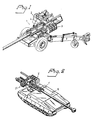
- Figs. 1 and 2 show examples of large-calibre weapons, on which the loading device according to the present invention may be used.
- Fig. 1 shows a Bofors field howitzer FH 77, designated reference numeral 1, whose design and construction are per se known and will therefore not be described in greater detail here.
- the novel loading device according to the present invention is represented by two magazines 2 and 3, hereinafter designated first magazine 2 and second magazine 3.
- the first magazine 2 is disposed in a carrier 4 which is anchored in the traversing system of the weapon.
- the second magazine 3 is disposed in a carrier 5 which is anchored in the elevating mass of the weapon.
- the magazines are located at the rear regions of the weapon, the magazine 2 being disposed on the right-hand side and the magazine 3 on the left-hand side.
- the loading device is shown mounted on a weapon 1' disposed on a tracked vehicle 6 of per se known type.
- the magazines are designated 2' and 3' respectively.
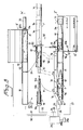
- transfer devices are arranged at each respective magazine 2'', 3''.
- One transfer device 7 at the first magazine 2'' includes a loading pendulum 7a and a loading bridge which is disposed thereon and is shown in a receiving position at the magazine 2'' by reference numeral 7b, and in a position inwardly pivoted to the axis of the bore 1a of the weapon by reference numeral 7b'.
- the loading bridge may be journalled in a known manner in pivotal arms which, in a corresponding manner, are shown in two positions 7c and 7d and 7c' and 7d' respectively.
- the journalling of the loading bridge is of a special design in that the arms and their journallings in the bridge permit the bridge to be pivoted inwardly from position 7b to position 7b' following an elliptical path 8.
- the loading bridge executes, at the end of its inward pivoting movement, a longitudinal displacement movement substantially coinciding with the axis of the bore of the weapon.
- the arrangement also includes loading channel portions 7e and 7f which, in the receiving position of the transfer device 7, are opposed to one another such that a projectile 10 located in the discharge position 9 of the magazine may pass via the starting position and the channel portions 7e and 7f down on to the loading bridge.
- a projectile fed down onto the loading bridge is indicated by reference numeral 10'.
- the loading bridge is fitted with shock absorbers which are symbolically intimated by reference numeral 11.
- the magazine 2' is fitted with a releasable locking member 12 which may be of per se known type, for example with hydraulic or magnetic control 13.
- a characteristic feature of the first magazine 2' is that its longitudinal axis, in accordance with the disclosures below, inclines in relation to a horizontal plane, so that on release of the locking member the projectile 10 slides down on to the loading bridge by its own weight. This considerably simplifies the construction of the first magazine which, for instance, need not be provided with various discharge devices for different projectile lengths.
- the outward sliding direction is indicated by the arrow 14 in Fig. 3.
- Each respective magazine space is provided with its locking member 12', 12'', and so on.
- the release function 13 may consist of a piston 13a which may be projected into a recess 12b in each respective locking member. When the piston 13a is moved in through the recess, the lock 12 is actuated (released) by the intermediary of a fulcrum arrangement of per se known type.
- Each respective magazine space 2a also includes an activation device 15 which is longitudinally displaceably disposed in the above-mentioned space.
- the activation device may be allocated a position where it interacts with the forward regions of each respective projectile which normally include fuzes or the like adjustable in response to the activation device 15.
- the weapon includes a rammer 16 allocated to the projectiles and disposed in the cradle of the weapon.
- the rammer is provided with a rammer head 16a which Is disposed at the end of a telescopic portion 16b which, in a per se known manner, is disposed to be protractible by means of a piston 16c.
- the rammer is located behind the inward pivotal position 7b' of the loading bridge. The arrangement is such that the rammer is actuated/started before the loading bridge 7b has completed its inward pivotal movement along the elliptical path 8.
- the rammer When the loading bridge reaches the axis of the bore 1a, the rammer catches up the loading bridge enabling the rammer head 16a to enter into interaction with the rear plane of the projectile. The holding function of the loading bridge for the projectile is released before the rammer head 16a enters into interaction with the rear plane.
- the rammer operates at a higher speed than the loading bridge and, with the aid of inherent kinetic energy in the projectile, will readily further accelerate the projectile so that it is thrown forwardly into the chamber 1b and, by free flight in its final phase, reaches its ramming position at the start of the barrel rifling 1c.
- the rammer may be withdrawn and the loading bridge returned to its position 7b to receive a new projectile from the magazine which has been advanced (rotated) so that the magazine space with a projectile is placed in the discharge position 9, and so on.
- the loading device also includes second transfer devices which transfer charges/cartridges 17 from the magazine to a defined position behind a thus rammed projectile.
- the second transfer device includes a cartridge canister 18 which may be registered with a discharge position 19 for the second magazine. In the discharge position, the cartridge 17 may be longitudinally displaced out into the canister with the aid of a displacement member 20 which is disposed at the forward end of the magazine.
- the displacement member may consist of a hydraulic cylinder, pneumatic cylinder, chain arrangement, etc.
- the displacement member includes a plate 20b which can interact with one end 17a of the cartridge. The direction of displacement is indicated by reference numeral 21.
- the second magazine is provided with a guide channel portion 22 via which the cartridge passes on its passage out into the cartridge canister.
- the cartridge canister is journalled in arms, of which only one, designated 23, is shown in the figure.
- the journalling and design of the arms 23 may be of per se known manner.
- the cartridge canister is special, in that it fixedly clamps a discharged cartridge and holds this fixedly clamped until such time as the cartridge has been pivoted into the defined position behind the rear face of the projectile.
- the clamping devices are released and the canister may be withdrawn to its starting position at the magazine.
- a doctor, or extractor mechanism enters into interaction with the rear portion of the cartridge, causing the cartridge to remain in the space vacated by the canister.
- the inward pivoting movement is indicated by the arrows 24, 25.
- the above-disclosed subfunctions may be controlled from a central unit (e.g. the computer unit of the gun) 26.
- a number of these functions may be controlled by the movement functions of the gun and/or the loading device in a per se known manner.
- Such controls have been symbolically intimated in Fig. 3 by different connection leads. Via one lead (connection) 27, operation of the rotation of the first magazine 2'' will be obtained.
- the connections 28 and 29 symbolize the actuation of the pendulum and loading bridge movements.
- the second magazine 3'' is controlled by a connection 30.
- the cartridge canister is controlled via the connection 31 and the rammer via the connection 32.
- the release device 13 is controlled via a connection 33, 33' and the displacement member 20 via a connection 34, 34′.
- the control unit 26 may then be arranged so that, for instance, the movements of the loading bridge 7b and the rammer 16 are coordinated so that uniform acceleratory movement is obtained for the projectile from the starting position 7b up to the ramming position at the start of the barrel rifling 1c.
- the loading pendulum is controlled so that it is set to collect a projectile in the magazine position (discharge position), whereafter it is guided into the current elevation position of the barrel. From this set elevation position, the loading bridge 7b is actuated in accordance with the above disclosures.
- the unit 26 may include or be connected to an operating panel 26a for operating the loading functions.
- the unit may be disposed or arranged at a distance from the gun.
- a connection 26b between the panel 26a and the unit 26 consists of a wired or wireless connection. In the event that the gun is track-mounted (cf. Fig. 2), this may be effected in a sound-insulated mode for high levels.
- Fig. 4 illustrates int. al. the journalling of the first magazine 2 and the pendulum 7a, as well as of the loading bridge 7f.
- the first magazine is tiltably carried in a journal 35 of the carriage 4.
- the tilting movements are achieved with the aid of a cylinder 36.
- the magazine In the firing position of the weapon 1 illustrated in Fig. 4, the magazine assumes a tilted position with the angle of tilt ⁇ .
- the magazine In off-road manoeuvring, the magazine can be collapsed to a horizontal position which corresponds to the position illustrated in Fig. 1 for the magazine 3.
- the loading pendulum 7a is actuated by a cylinder 37.
- the cylinder is controlled in accordance with the above disclosures from the unit 26.
- the loading pendulum assumes a position which corresponds to the position of elevation of the weapon 1.
- the cylinder for elevating the weapon 1 is also indicated by means of reference numeral 38.
- the platform of the traversing system is indicated by reference numeral 39 and the pendulum journal by reference numeral 7g.
- Fig. 5 illustrates the elevation and depression function of the rammer 16 (see Fig. 3).
- the portion 16b is displaceable in parallel by means of two arms 16d and 16e which, at the bottom, guide in a cam 40 which, at its one end, displays a curved portion 40a.
- the one arm 16d is L-shaped at the bottom and, together with the arm 16e, is arranged so that when the portion 16b is displaced forwardly, for instance by a chain drive (not shown in detail), the arms are raised to the positions 16d' and 16e' respectively, whereupon parallel displacement (elevation) of the portion 16b takes place to the position 16b'. In this position, the portion 16b is parallel with the axis of the bore 1a.
- the rammer head assumes a position 16a', where it has entered into interaction with the rear face of the projectile 10''.
- the rammer head is designed with mutually angled portions 16a', 16a'', of which the one portion 16a' is capable of interaction with a side surface on the projectile so that this is kept raised by the rammer head.
- the portion 16a'' functions as a direct shunting surface for the rear plane of the projectile.
- the design of the head may be varied and it is conceivable that the rammer head could be capable of gripping the projectile at additional points.
- the most forward position of the rammer is indicated by the arm positions 16d'', 16e'', and the position 16b'' for the part 16b.
- the part 16b' may be inherently telescopic with two or more telescope sections.
- One such telescope section is illustrated by reference numeral 16f, and this telescope section is displaced in relation to the part 16b' by means of a piston device (see 16c in Fig. 5).
- the telescopic function is actuable at the same time as the travel movement of the rammer is executed. Alternatively, the travel movement is first executed, followed by the telescoping movement, or vice versa.
- the rammer is depressable below a defining line 41 of the recoil of the breech block.
- the design and control of the rammer may be realized in per se known manners and with per se known parts.
- Fig. 6 shows retention means 42 and 43 for a projectile placed on the loading bridge.
- the retention means include linkage arms 44, 45 which, at their ends, carry interacting members 46, 47 which, in response to linkage arm actuation, are capable of interaction with portions, for example the driving band, on the projectile.
- the arms are actuated by means of an activator 48 which receives control signals in response to the movements of the loading bridge, control signals from the control unit 26 (Fig. 3) or the like.
- the design and function of the retention means, as well as their control function may be effected in a per se known manner and will not, therefore, be described in greater detail here.
- the retention means are intended to be activated when the projectile has been fed down onto the loading bridge and is to be released (triggered) when the rammer 16a enters into interaction with the rear plane of the projectile, or immediately prior thereto.
- Fig. 7 shows the cartridge canister 18 which, in the illustrated embodiment, consists of two separable halves/parts 18a and 18b which are dish-shaped. In the opened position, each respective cartridge is insertable into the cartridge canister and, in the closed position of the canister halves, these clamp about the cartridge/cartridges so that a fixed retention function is created.
- the cartridge canister and cartridge may be arranged so that the cartridge canister permits a certain forward projection overhang for the cartridge which, in such cases, is rigid. This affords advantages in long and bulky charges and tight gun chamber spaces.
- the canister halves 18a and 18b are mutually guided by guide members 48, 49.
- the guiding function may be realized in a number of per se known manners and may be initiated by movements in the parts of the loading device, the parts of the weapon itself or be controlled from the above-mentioned unit 26.
- Fig. 8 illustrates an example of guiding by means of linkage arms.
- Two arms 50, 51 are pivotally journalled at points 52, 53.
- the arms 50 and 51 are jointly journalled at their other ends in a journal 54 and this journal is actuable by means of an activation arrangement 55, 56, 57 disposed such that the journalling point is displaceable in the longitudinal direction of the cartridge canister in response to activation movements.
- the journalling point 54 assumes a position in which the canister halves 18a, 18b have been drawn to the right in the Figure so that they clamp about an inserted cartridge or cartridges. On displacement to the left in Fig.
- journalling points 52 and 53 are urged in a direction away from one another, implying that the canister halves are separated, which makes it possible to sweep the cartridge from the cartridge canister.
- An arrangement as shown in Fig. 8 is provided in each respective canister end.
- Fig. 9 is intended to illustrate schematically how the elliptical movement 8 (see Fig. 3) for the projectiles is realized.
- the arm 7d is fitted with an angled portion 7h via which the arm guides into a cam 58.
- the actuation cylinder is indicated by reference numeral 59.
- the position of the part 7h has here been indicated by reference numeral 7h'.
- Corresponding cam guidance is provided for the second am 7c of the bridge.
- the sweeping function for each respective cartridge from the cartridge canister into the weapon proper has been schematically indicated by reference numeral 61.
- the sweeping function is controlled mechanically or electrically.
- the sweeper device 61 may be set in motion via 62 from one of the parts of the loading device or the weapon proper.
- Each respective magazine 2, 3 has a capacity of eight projectiles/cartridges.
- One projectile/cartridge may be placed on the loading bridge or in the canister, respectively.
- One projectile may further be rammed home, which together gives a total number of nine projectiles and a total number of eight cartridges prior to firing a salvo.
Landscapes
- Engineering & Computer Science (AREA)
- General Engineering & Computer Science (AREA)
- Toys (AREA)
- Elimination Of Static Electricity (AREA)
- Vehicle Body Suspensions (AREA)
- Electrical Discharge Machining, Electrochemical Machining, And Combined Machining (AREA)
- Vending Machines For Individual Products (AREA)
Abstract
Description
- The present invention relates to a loading device in large-calibre weapons, the device being arranged to allow firing with rounds consisting of projectiles of different types, lengths, etc., and charges of different sizes, preferably in form of cartridges, combinable with the projectiles in the weapon on loading.
- In wheelborne large-calibre weapons, for example field howitzers, and in tracked large-calibre weapons, MBTs, it is previously known to carry out firing with split ammunition which consists of projectiles and their associated charges/cartridges. The prior art loading devices may be regarded as mechanical aids for the loading function. Each respective projectile is applied by means of a loading platform and the like to a pivoting loading bridge which is swung in to the axis for the bore of the weapon. The cartridge or cartridges are similarly inserted in the axis of the bore of the weapon and the entire unit is rammed home using a rammer. The prior-art loading procedures have hitherto required the participation of members of the gun crew in different stages of the loading cycle.
- EP-A1-0 051 119 discloses an automatic loading system for split ammunitions necessary under said circumstances.
- At long ranges, for example of the order of 40 kilometres and longer, noise levels become very high indeed (185 dB), with the result that the gun crew cannot be stationed in the vicinity of the weapon at the moment of firing without running the risk of serious injury.
- Consequently, wishes have been expressed in this context for fully automatic loading systems which ensure reliable and safe loading cycles. The requirement is then that salvos of a given number of rounds to be fireable. After firing, rapid re-deployment of the artillery weapon (or the MBT) must be possible, as well as efficient reloading.
- The demand for greater ranges, firing with varied ammunition, shorter loading cycles etc place steadily growing demands on the loading function of the type of weapon under consideration here. Especially the demands on rapid loading have increased on large calibre weapons.
- The propellant charges for long ranges take up a considerable amount of space in and around the weapon and it is also a matter of some urgency that the fully automatic loading system does not encroach upon the elevation and traversing angle fields of the weapon, or impair the manoeuvreability of the weapon in the field etc.
- The largest charges for weapons of the type contemplated here may be designed with large diameters, which gives rise to problems in the ramming and extraction or sweeping functions.
- The object of the present invention is to propose a loading device which makes for a fully automated loading function in which the various problems outlined above may be obviated.
- That which may substantially be considered as characterizing the novel device according to the present invention is int. al.. that the first transfer device/loading bridge is preferably arranged so as to perform an elliptical movement on inward pivoting of each respective projectile to the axis of the bore. The rammer is preferably mounted in the cradle of the weapon and is arranged such that it commences its ramming movement for the projectile placed on the loading bridge before the inward pivoting movement of the loading bridge is completed. The rammer then operates at a ramming speed which exceeds the inward pivoting speed of the loading bridge. In this manner, the rammer catches up the loading bridge for commencement of the ramming process before the loading bridge has fully completed its inward pivoting movement. By this means, the inward pivoting and ramming functions can dovetail together in an unbroken advancement movement for the projectile and an efficient and rapid ramming function will be obtained in which ramming function the projectile is accelerated and thrown into the chamber in free flight.
- In one embodiment of the device according to the present invention, each respective projectile is rammed home with the aid of a loading bridge and the rammer which may then be considered to have been allocated the projectile. Each respective charge/cartridge is placed without rammer directly in place with the aid of a retention function in the second transfer device, for example in the form of a cartridge canister.
- In a further embodiment of the device according to the present invention, the first magazine may include a first revolver magazine placed at the first side of the weapon (rearwardly at the breech block), this revolver magazine being arranged with its longitudinal axis inclining in relation to a horizontal plane. By this means, each respective projectile can be discharged from the first magazine by the projectile's own weight. In this way, no individual feed mechanism for each respective projectile length in the magazine need be provided. The first magazine may be disposed on the traversing system of the weapon, the first transfer device then being in the form of a loading pendulum and a loading bridge inwardly and outwardly pivotally disposed thereon, the loading bridge being fitted with releasable retention members for each respective projectile. The weapon can thus be fired with a projectile on the loading bridge.
- The locking members of the loading bridge are releasable before the rammer enters into interaction with the projectile placed on the loading bridge. In one embodiment, the rammer is designed, during its interaction with each respective projectile, to hold the rear portion of the projectile in a raised position during the ramming operation proper, so as to avoid jamming. The rammer is further designed to be foldable up and down so as to allow for the passage of the breech block above the rammer on recoil.
- The second magazine also preferably includes a second revolver magazine disposed on the elevating mass of the weapon on the other side of the weapon. The second transfer device is preferably designed with a cartridge canister secured to the elevating mass of the weapon. The second transfer device is provided with retention means of its own which fixedly clamp the charge/cartridge during the inward pivoting movement to the defined position behind its associated projectile. The retention means may be triggered when, or just before, the charge/cartridge assumes its position behind the projectile so as to make possible extraction, by the extractor, of the charge/cartridge from the second transfer device/cartridge canister.
- The above-mentioned magazine control device includes, in one embodiment, means for displacing/rotating the magazine and devices for releasing the projectile and reeding out the charge/cartridge. The first magazine may be designed with adaptors in each respective space for the projectiles. These adaptors are longitudinally displaceable and include activator devices for the fuzes of the projectiles.
- The arrangement described in the foregoing makes for a reliable fully automatic loading function with a relatively simple technical construction. Redesign of existing basic models of the weapon will be unnecessary, since the novel loading device makes no inroads into the elevation and traverse areas, even though the system enables firing to be carried out at long ranges. Hence, the novel loading device according to the present invention can be applied to existing weaponry designs or be integrated in the weapon on new manufacture. The charge employed may be allowed to fill out the whole of the barrel chamber without having any effect on the loading function. Risks of jamming can be avoided where such occur. The magazine can be placed on available spaces on the artillery gun, i.e. on those places which, on conventional weapons, would normally be occupied by gun loader and layer. Firing with a projectile already on the loading bridge can be carried out thanks to the locking function of the loading bridge on the projectile. The magazine may readily be adjusted for projectiles and cartridges of different lengths, types, sizes, etc. The magazine is designed for, say, nine projectiles/cartridges, this constituting a number which is considered as appropriate from the practical point of view.
- The nature of the present invention and its aspects will be more readily understood from the following brief description of the accompanying Drawings and discussion relating thereto of one currently proposed embodiment thereof.
- In the accompanying Drawings:
- Fig. 1 is a perspective view obliquely from above of the loading device employed in a per se known wheelborne large-calibre weapon (FH 77);
- Fig. 2 is a perspective view obliquely from above of the loading device employed on a tracked large-calibre weapon, similarly of per se known type;
- Fig. 3 is a horizontal view schematically illustrating parts included in the loading device;
- Fig. 4 is a side elevation of a first magazine for projectiles, with associated transfer devices including a loading pendulum and loading bridge journalled thereon;
- Fig. 5 is a schematic side elevation illustrating upwardly and downwardly foldable ramming devices for the projectiles, disposed in the cradle of the weapon;
- Fig. 6 is a vertical section showing the loading bridge with associated clamping members for a projectile fed down onto the loading bridge;
- Fig. 7 is a vertical section through a cartridge canister which is provided for fixedly clamping the cartridges during the transfer movement from the cartridge magazine to a defined position behind its associated, rammed projectile;
- Fig. 8 shows actuation devices which realize fixed clamping of the cartridges during the inward pivoting of each respective cartridge into the axis of the bore of the weapon; and
- Fig. 9 is a side elevation schematically illustrating the control arrangement (cam) for the loading bridge.
- Referring to the Drawings, Figs. 1 and 2 show examples of large-calibre weapons, on which the loading device according to the present invention may be used. Fig. 1 shows a Bofors
field howitzer FH 77, designated reference numeral 1, whose design and construction are per se known and will therefore not be described in greater detail here. In Fig. 1, the novel loading device according to the present invention is represented by twomagazines first magazine 2 andsecond magazine 3. Thefirst magazine 2 is disposed in acarrier 4 which is anchored in the traversing system of the weapon. Thesecond magazine 3 is disposed in acarrier 5 which is anchored in the elevating mass of the weapon. The magazines are located at the rear regions of the weapon, themagazine 2 being disposed on the right-hand side and themagazine 3 on the left-hand side. - In Fig. 2, the loading device is shown mounted on a weapon 1' disposed on a tracked
vehicle 6 of per se known type. In this case, the magazines are designated 2' and 3' respectively. - According to Fig. 3, transfer devices are arranged at each respective magazine 2'', 3''. One transfer device 7 at the first magazine 2'' includes a
loading pendulum 7a and a loading bridge which is disposed thereon and is shown in a receiving position at the magazine 2'' byreference numeral 7b, and in a position inwardly pivoted to the axis of thebore 1a of the weapon byreference numeral 7b'. The loading bridge may be journalled in a known manner in pivotal arms which, in a corresponding manner, are shown in twopositions position 7b to position 7b' following anelliptical path 8. As a result of this arrangement, the loading bridge executes, at the end of its inward pivoting movement, a longitudinal displacement movement substantially coinciding with the axis of the bore of the weapon. - The arrangement also includes loading channel portions 7e and 7f which, in the receiving position of the transfer device 7, are opposed to one another such that a projectile 10 located in the
discharge position 9 of the magazine may pass via the starting position and the channel portions 7e and 7f down on to the loading bridge. A projectile fed down onto the loading bridge is indicated by reference numeral 10'. Rearwardly, the loading bridge is fitted with shock absorbers which are symbolically intimated byreference numeral 11. The magazine 2' is fitted with a releasable lockingmember 12 which may be of per se known type, for example with hydraulic ormagnetic control 13. A characteristic feature of the first magazine 2' is that its longitudinal axis, in accordance with the disclosures below, inclines in relation to a horizontal plane, so that on release of the locking member the projectile 10 slides down on to the loading bridge by its own weight. This considerably simplifies the construction of the first magazine which, for instance, need not be provided with various discharge devices for different projectile lengths. The outward sliding direction is indicated by thearrow 14 in Fig. 3. Each respective magazine space is provided with its locking member 12', 12'', and so on. Therelease function 13 may consist of apiston 13a which may be projected into arecess 12b in each respective locking member. When thepiston 13a is moved in through the recess, thelock 12 is actuated (released) by the intermediary of a fulcrum arrangement of per se known type. - Each
respective magazine space 2a also includes anactivation device 15 which is longitudinally displaceably disposed in the above-mentioned space. The activation device may be allocated a position where it interacts with the forward regions of each respective projectile which normally include fuzes or the like adjustable in response to theactivation device 15. - The weapon includes a
rammer 16 allocated to the projectiles and disposed in the cradle of the weapon. The rammer is provided with arammer head 16a which Is disposed at the end of atelescopic portion 16b which, in a per se known manner, is disposed to be protractible by means of apiston 16c. The rammer is located behind the inwardpivotal position 7b' of the loading bridge. The arrangement is such that the rammer is actuated/started before theloading bridge 7b has completed its inward pivotal movement along theelliptical path 8. When the loading bridge reaches the axis of thebore 1a, the rammer catches up the loading bridge enabling therammer head 16a to enter into interaction with the rear plane of the projectile. The holding function of the loading bridge for the projectile is released before therammer head 16a enters into interaction with the rear plane. The rammer operates at a higher speed than the loading bridge and, with the aid of inherent kinetic energy in the projectile, will readily further accelerate the projectile so that it is thrown forwardly into thechamber 1b and, by free flight in its final phase, reaches its ramming position at the start of the barrel rifling 1c. After the ramming operation carried out in this manner, the rammer may be withdrawn and the loading bridge returned to itsposition 7b to receive a new projectile from the magazine which has been advanced (rotated) so that the magazine space with a projectile is placed in thedischarge position 9, and so on. - The loading device also includes second transfer devices which transfer charges/
cartridges 17 from the magazine to a defined position behind a thus rammed projectile. The second transfer device includes acartridge canister 18 which may be registered with adischarge position 19 for the second magazine. In the discharge position, thecartridge 17 may be longitudinally displaced out into the canister with the aid of a displacement member 20 which is disposed at the forward end of the magazine. The displacement member may consist of a hydraulic cylinder, pneumatic cylinder, chain arrangement, etc. The displacement member includes a plate 20b which can interact with oneend 17a of the cartridge. The direction of displacement is indicated byreference numeral 21. The second magazine is provided with aguide channel portion 22 via which the cartridge passes on its passage out into the cartridge canister. The cartridge canister is journalled in arms, of which only one, designated 23, is shown in the figure. The journalling and design of thearms 23 may be of per se known manner. The cartridge canister is special, in that it fixedly clamps a discharged cartridge and holds this fixedly clamped until such time as the cartridge has been pivoted into the defined position behind the rear face of the projectile. When the cartridge canister reaches its inwardly pivoted position, or immediately before this position, the clamping devices are released and the canister may be withdrawn to its starting position at the magazine. Before the return to the starting position, a doctor, or extractor mechanism, enters into interaction with the rear portion of the cartridge, causing the cartridge to remain in the space vacated by the canister. In Fig. 3, the inward pivoting movement is indicated by thearrows - The above-disclosed subfunctions may be controlled from a central unit (e.g. the computer unit of the gun) 26. Alternatively, a number of these functions may be controlled by the movement functions of the gun and/or the loading device in a per se known manner. Such controls have been symbolically intimated in Fig. 3 by different connection leads. Via one lead (connection) 27, operation of the rotation of the first magazine 2'' will be obtained. The
connections connection 30. The cartridge canister is controlled via theconnection 31 and the rammer via theconnection 32. Therelease device 13 is controlled via aconnection 33, 33' and the displacement member 20 via aconnection control unit 26 may then be arranged so that, for instance, the movements of theloading bridge 7b and therammer 16 are coordinated so that uniform acceleratory movement is obtained for the projectile from the startingposition 7b up to the ramming position at the start of the barrel rifling 1c. The loading pendulum is controlled so that it is set to collect a projectile in the magazine position (discharge position), whereafter it is guided into the current elevation position of the barrel. From this set elevation position, theloading bridge 7b is actuated in accordance with the above disclosures. Theunit 26 may include or be connected to anoperating panel 26a for operating the loading functions. In those cases when a gun crew may not be stationed in the vicinity of the gun while firing takes place, the unit may be disposed or arranged at a distance from the gun. Aconnection 26b between thepanel 26a and theunit 26 consists of a wired or wireless connection. In the event that the gun is track-mounted (cf. Fig. 2), this may be effected in a sound-insulated mode for high levels. - Fig. 4 illustrates int. al. the journalling of the
first magazine 2 and thependulum 7a, as well as of the loading bridge 7f. The first magazine is tiltably carried in ajournal 35 of thecarriage 4. The tilting movements are achieved with the aid of acylinder 36. In the firing position of the weapon 1 illustrated in Fig. 4, the magazine assumes a tilted position with the angle of tilt α. In off-road manoeuvring, the magazine can be collapsed to a horizontal position which corresponds to the position illustrated in Fig. 1 for themagazine 3. Theloading pendulum 7a is actuated by a cylinder 37. The cylinder is controlled in accordance with the above disclosures from theunit 26. The loading pendulum assumes a position which corresponds to the position of elevation of the weapon 1. In Fig. 4, the cylinder for elevating the weapon 1 is also indicated by means ofreference numeral 38. The platform of the traversing system is indicated byreference numeral 39 and the pendulum journal byreference numeral 7g. - Fig. 5 illustrates the elevation and depression function of the rammer 16 (see Fig. 3). The
portion 16b is displaceable in parallel by means of twoarms curved portion 40a. The onearm 16d is L-shaped at the bottom and, together with thearm 16e, is arranged so that when theportion 16b is displaced forwardly, for instance by a chain drive (not shown in detail), the arms are raised to thepositions 16d' and 16e' respectively, whereupon parallel displacement (elevation) of theportion 16b takes place to theposition 16b'. In this position, theportion 16b is parallel with the axis of thebore 1a. The rammer head assumes aposition 16a', where it has entered into interaction with the rear face of the projectile 10''. The rammer head is designed with mutuallyangled portions 16a', 16a'', of which the oneportion 16a' is capable of interaction with a side surface on the projectile so that this is kept raised by the rammer head. Theportion 16a'' functions as a direct shunting surface for the rear plane of the projectile. The design of the head may be varied and it is conceivable that the rammer head could be capable of gripping the projectile at additional points. The most forward position of the rammer is indicated by the arm positions 16d'', 16e'', and theposition 16b'' for thepart 16b. - The
part 16b' may be inherently telescopic with two or more telescope sections. One such telescope section is illustrated byreference numeral 16f, and this telescope section is displaced in relation to thepart 16b' by means of a piston device (see 16c in Fig. 5). The telescopic function is actuable at the same time as the travel movement of the rammer is executed. Alternatively, the travel movement is first executed, followed by the telescoping movement, or vice versa. The rammer is depressable below a definingline 41 of the recoil of the breech block. The design and control of the rammer may be realized in per se known manners and with per se known parts. - Fig. 6 shows retention means 42 and 43 for a projectile placed on the loading bridge. In the illustrated embodiment, the retention means include
linkage arms 44, 45 which, at their ends, carry interactingmembers activator 48 which receives control signals in response to the movements of the loading bridge, control signals from the control unit 26 (Fig. 3) or the like. The design and function of the retention means, as well as their control function, may be effected in a per se known manner and will not, therefore, be described in greater detail here. The retention means are intended to be activated when the projectile has been fed down onto the loading bridge and is to be released (triggered) when therammer 16a enters into interaction with the rear plane of the projectile, or immediately prior thereto. - Fig. 7 shows the
cartridge canister 18 which, in the illustrated embodiment, consists of two separable halves/parts guide members unit 26. - Fig. 8 illustrates an example of guiding by means of linkage arms. Two
arms points arms journal 54 and this journal is actuable by means of anactivation arrangement journalling point 54 assumes a position in which thecanister halves - Fig. 9 is intended to illustrate schematically how the elliptical movement 8 (see Fig. 3) for the projectiles is realized. The
arm 7d is fitted with anangled portion 7h via which the arm guides into acam 58. The actuation cylinder is indicated byreference numeral 59. On actuation of the piston of the cylinder in the direction of thearrow 60, the arrangement ensures that the arm may assume theposition 7d' (cf. Fig. 3). The position of thepart 7h has here been indicated byreference numeral 7h'. Corresponding cam guidance is provided for thesecond am 7c of the bridge. - In Fig. 3, the sweeping function for each respective cartridge from the cartridge canister into the weapon proper has been schematically indicated by
reference numeral 61. The sweeping function is controlled mechanically or electrically. For instance, thesweeper device 61 may be set in motion via 62 from one of the parts of the loading device or the weapon proper. Eachrespective magazine
Claims (9)
- In large-calibre weapons, a loading device arranged to make possible firing with rounds consisting of projectiles (10) of different types, lengths, etc., and charges of different sizes, preferably in the form of cartridges (17) which may be combinable with the projectiles in the weapon on loading, and wherein the projectiles may be placed in a first magazine (2) from which each respective projectile is transferrable by means of first transfer devices (7) to the axis of the bore (1a) of the weapon for interaction with a ramming device (16) which is arranged to ram home into the weapon each respective projectile placed in the axis of the bore; the charges/cartridges are placed in a second magazine (3), from which each respective charge/cartridge is transferrable by means of second transfer devices to a defined position behind the associated projectile rammed home by the rammer device; and the transfer and rammer devices are arranged, together with magazine control devices (26), to co-function in a fully automatic loading function for the projectiles and the charges/cartridges, characterized in that the first transfer device/loading bridge is disposed, on inward pivoting of each respective projectile to the axis of the bore, to impart to the projectile an elliptical path (8); and that said rammer device (16) is disposed in the cradle of the weapon and is arranged to commence its ramming movement for the projectile placed on the loading bridge before the inward pivoting of the loading bridge to the axis of the bore (1a) has been completed; and that the rammer device operates at a ramming speed which exceeds the inward pivoting speed of the loading bridge so that the ramer device catches up the loading bridge for commencement of the ramming cycle, which includes in its final phase, free flight of the projectile.
- The device as claimed in Claim 1, characterized in that said first magazine (2) includes a first revolver magazine placed on the first side of the weapon, and disposed with its longitudinal axis inclining in relation to a horizontal plane so as to make possible discharge of each respecitive projectile from the first magazine with the aid of the projectile's own weight.
- The device as claimed in Claim 1 or 2, characterized in that said first magazine (2') is disposed on the traversing system of the weapon; and that said first transfer device includes a loading pendulum (7a) and a loading bridge (7b) inwardly and outwardly pivotally disposed thereon and provided with releasable retention means (46, 47) for each respective projectile.
- The device as claimed in Claim 2 or 3, characterized in that the releasable retention means (46, 47) of the loading bridge are releasable before the rammer device enters into interaction with the projectile placed on the loading bridge.
- The device as claimed in any one of the preceding Claims, characterized in that the rammer device (16) is disposed, during its interaction with each respective projectile, to hold the rear portion thereof raised so as to avoid jamming effects; and that the rammer device is upwardly and downwardly foldable so as to allow for the passage of the breech block on recoil.
- The device as claimed in any one of the preceding Claims, characterized in that the second magazine includes a second revolver magazine disposed on the elevating mass of the weapon, at the other side of the weapon.
- The device as claimed in any one of the preceding Claims, characterized in that the second transfer device includes a cartridge canister (18) disposed on the elevating mass of the weapon.
- The device as claimed in any one of the preceding Claims, characterized in that the second transfer device including a cartridge cannister (18) is provided with its own retention means (18a, 18b) which fixedly clamp the charge/cartridge during the inward pivoting movement to the defined position behind the associated projectile; and that said retention means are triggerable when, or immediately before, the charge/cartridge assumes its position behind the projectile so as to make possible the sweeping, by a sweeper device, of the charge/cartridge from the second transfer device/cartridge canister.
- The device as claimed in any one of the preceding Claims, characterized in that the co-function in the fully automatic loading function for the projectiles and the charges/cartridges also takes place in interaction with a sweeper device (61) for the cartridge/charges; that the magazine control devices (26) include means for the rotation/displacement of the magazines, and projectile release and charge/cartridge displacement members (20); and that the space of the first magazine for the projectile includes longitudinally displaceable actuation members for the fuzes of the projectiles, the longitudinal displaceable capability making possible adaptation to different projectile lengths.
Priority Applications (1)
| Application Number | Priority Date | Filing Date | Title |
|---|---|---|---|
| AT89850309T ATE97228T1 (en) | 1988-09-21 | 1989-09-19 | CHARGING DEVICE. |
Applications Claiming Priority (2)
| Application Number | Priority Date | Filing Date | Title |
|---|---|---|---|
| SE8803335A SE468610B (en) | 1988-09-21 | 1988-09-21 | CHARGING DEVICE |
| SE8803335 | 1988-09-21 |
Publications (2)
| Publication Number | Publication Date |
|---|---|
| EP0360776A1 EP0360776A1 (en) | 1990-03-28 |
| EP0360776B1 true EP0360776B1 (en) | 1993-11-10 |
Family
ID=20373398
Family Applications (1)
| Application Number | Title | Priority Date | Filing Date |
|---|---|---|---|
| EP89850309A Expired - Lifetime EP0360776B1 (en) | 1988-09-21 | 1989-09-19 | A loading device |
Country Status (5)
| Country | Link |
|---|---|
| US (1) | US4991489A (en) |
| EP (1) | EP0360776B1 (en) |
| AT (1) | ATE97228T1 (en) |
| DE (1) | DE68910629D1 (en) |
| SE (1) | SE468610B (en) |
Cited By (1)
| Publication number | Priority date | Publication date | Assignee | Title |
|---|---|---|---|---|
| EP2405227B1 (en) | 2010-07-08 | 2016-08-10 | Krauss-Maffei Wegmann GmbH & Co. KG | Loading device and method for loading a weapon with separated munition and artillery gun with a weapon and a loading device |
Families Citing this family (11)
| Publication number | Priority date | Publication date | Assignee | Title |
|---|---|---|---|---|
| SE9304188L (en) * | 1993-12-17 | 1995-02-06 | Bofors Ab | Ammunition management system for artillery pieces |
| SE503490C2 (en) * | 1994-10-13 | 1996-06-24 | Bofors Ab | ammunition Carrier |
| US6481328B1 (en) * | 2000-01-05 | 2002-11-19 | Bofors Defense Ab | Method and device for handling propellant charges |
| US6513415B2 (en) * | 2001-03-22 | 2003-02-04 | United Defense Lp | Propellant retention device |
| SE520361C2 (en) * | 2001-12-05 | 2003-07-01 | Alvis Haegglunds Ab | Device for transferring coarse-caliber ammunition from an ammunition magazine to a charging position on a coarse-caliber weapon |
| RU2215965C2 (en) * | 2002-01-31 | 2003-11-10 | Федеральное государственное унитарное предприятие Конструкторское бюро транспортного машиностроения | Combat compartment of tank ( variants ) |
| DE102004024302B4 (en) * | 2004-05-15 | 2008-04-10 | Kraus-Maffei Wegmann Gmbh & Co. Kg | Belt box for a mounted grenade machine weapon |
| US8033207B1 (en) * | 2008-06-06 | 2011-10-11 | The United States Of America As Represented By The Secretary Of The Army | Electrically actuated weapon system |
| US8215225B1 (en) * | 2010-06-03 | 2012-07-10 | The United States Of America As Represented By The Secretary Of The Army | Large caliber autoloader |
| CN103175441B (en) * | 2012-04-11 | 2014-11-05 | 湖北江华机械有限公司 | Grenade launcher ammunition feed mechanism |
| CN107941081B (en) * | 2017-11-28 | 2020-01-21 | 上海航天精密机械研究所 | Quick loading device of hand formula section of thick bamboo bullet |
Family Cites Families (9)
| Publication number | Priority date | Publication date | Assignee | Title |
|---|---|---|---|---|
| FR931240A (en) * | 1948-02-20 | |||
| US1360523A (en) * | 1920-06-22 | 1920-11-30 | Armstrong Whitworth Co Eng | Automatic gun |
| FR2205993A6 (en) * | 1971-12-07 | 1974-05-31 | France Etat | |
| SE392966B (en) * | 1974-01-15 | 1977-04-25 | Bofors Ab | AUTOMATMAGASIN |
| DE2413983A1 (en) * | 1974-03-22 | 1979-10-11 | Hopp Ing Buero | Automatic loader for armoured fighting vehicle gun - has drum with ammunition compartments indexed as required to gun barrel |
| SE431912B (en) * | 1979-12-18 | 1984-03-05 | Bofors Ab | loading pendulum |
| DE3168783D1 (en) * | 1980-08-27 | 1985-03-21 | Fmc Corp | Automatic large caliber ammunition loading system |
| US4457209A (en) * | 1980-08-27 | 1984-07-03 | Fmc Corporation | Automated large caliber ammunition handling system |
| DE3437588A1 (en) * | 1984-10-13 | 1986-04-24 | Rheinmetall GmbH, 4000 Düsseldorf | LOADING DEVICE FOR PROTECTIVE GUNS |
-
1988
- 1988-09-21 SE SE8803335A patent/SE468610B/en not_active IP Right Cessation
-
1989
- 1989-09-19 DE DE89850309T patent/DE68910629D1/en not_active Expired - Lifetime
- 1989-09-19 EP EP89850309A patent/EP0360776B1/en not_active Expired - Lifetime
- 1989-09-19 AT AT89850309T patent/ATE97228T1/en not_active IP Right Cessation
- 1989-09-20 US US07/409,662 patent/US4991489A/en not_active Expired - Fee Related
Cited By (1)
| Publication number | Priority date | Publication date | Assignee | Title |
|---|---|---|---|---|
| EP2405227B1 (en) | 2010-07-08 | 2016-08-10 | Krauss-Maffei Wegmann GmbH & Co. KG | Loading device and method for loading a weapon with separated munition and artillery gun with a weapon and a loading device |
Also Published As
| Publication number | Publication date |
|---|---|
| ATE97228T1 (en) | 1993-11-15 |
| DE68910629D1 (en) | 1993-12-16 |
| EP0360776A1 (en) | 1990-03-28 |
| SE468610B (en) | 1993-02-15 |
| SE8803335D0 (en) | 1988-09-21 |
| US4991489A (en) | 1991-02-12 |
Similar Documents
| Publication | Publication Date | Title |
|---|---|---|
| EP0784778B1 (en) | Ramming system | |
| US4991489A (en) | Loading device | |
| EP1102022B1 (en) | Automatic weapon with recoiling barrel | |
| EP0051119A1 (en) | Automatic large caliber ammunition loading system | |
| JPS6210360B2 (en) | ||
| US5811721A (en) | Ammunition feeder | |
| US5347911A (en) | Double-action rammer | |
| US4669357A (en) | Weapon system with barreled weapon in an armored vehicle | |
| EP0663583A1 (en) | Ordnance gun having pivoting magazines | |
| US6591733B1 (en) | Loading system | |
| US4690031A (en) | Automatic loader for an armored vehicle having a rotatable turret | |
| US4919038A (en) | Armoured car | |
| US4823675A (en) | Apparatus for loading guns, particularly tank howitzers | |
| GB1490112A (en) | Loading device for a large-bore firearm | |
| US5880395A (en) | Gun turret assembly for an armored vehicle | |
| US4945813A (en) | Rapid fire howitzer | |
| GB2225843A (en) | An automatic muzzle-loader weapon. | |
| US5390583A (en) | Single-action rammer | |
| GB1573498A (en) | Method of and device for loading a firearm | |
| US6752063B2 (en) | Multiple cell ammunition cradle | |
| US4135433A (en) | Loading device for a firearm | |
| JPS61501720A (en) | Device for delivering and loading bullets into a weapon in any direction and at any height | |
| US4898072A (en) | Weapon and ammunition carrier for a gun | |
| US5202531A (en) | Rammer | |
| US4738182A (en) | Cartridge casing ejector |
Legal Events
| Date | Code | Title | Description |
|---|---|---|---|
| PUAI | Public reference made under article 153(3) epc to a published international application that has entered the european phase |
Free format text: ORIGINAL CODE: 0009012 |
|
| AK | Designated contracting states |
Kind code of ref document: A1 Designated state(s): AT BE CH DE ES FR GB GR IT LI LU NL SE |
|
| 17P | Request for examination filed |
Effective date: 19900907 |
|
| 17Q | First examination report despatched |
Effective date: 19920204 |
|
| GRAA | (expected) grant |
Free format text: ORIGINAL CODE: 0009210 |
|
| AK | Designated contracting states |
Kind code of ref document: B1 Designated state(s): AT BE CH DE ES FR GB GR IT LI LU NL SE |
|
| PG25 | Lapsed in a contracting state [announced via postgrant information from national office to epo] |
Ref country code: IT Free format text: LAPSE BECAUSE OF FAILURE TO SUBMIT A TRANSLATION OF THE DESCRIPTION OR TO PAY THE FEE WITHIN THE PRE;WARNING: LAPSES OF ITALIAN PATENTS WITH EFFECTIVE DATE BEFORE 2007 MAY HAVE OCCURRED AT ANY TIME BEFORE 2007. THE CORRECT EFFECTIVE DATE MAY BE DIFFERENT FROM THE ONE RECORDED.SCRIBED TIME-LIMIT Effective date: 19931110 Ref country code: NL Effective date: 19931110 Ref country code: SE Effective date: 19931110 Ref country code: GR Free format text: LAPSE BECAUSE OF FAILURE TO SUBMIT A TRANSLATION OF THE DESCRIPTION OR TO PAY THE FEE WITHIN THE PRESCRIBED TIME-LIMIT Effective date: 19931110 Ref country code: ES Free format text: THE PATENT HAS BEEN ANNULLED BY A DECISION OF A NATIONAL AUTHORITY Effective date: 19931110 Ref country code: FR Effective date: 19931110 Ref country code: AT Effective date: 19931110 Ref country code: LI Effective date: 19931110 Ref country code: DE Effective date: 19931110 Ref country code: BE Effective date: 19931110 Ref country code: CH Effective date: 19931110 |
|
| REF | Corresponds to: |
Ref document number: 97228 Country of ref document: AT Date of ref document: 19931115 Kind code of ref document: T |
|
| REF | Corresponds to: |
Ref document number: 68910629 Country of ref document: DE Date of ref document: 19931216 |
|
| REG | Reference to a national code |
Ref country code: CH Ref legal event code: PL |
|
| EN | Fr: translation not filed | ||
| NLV1 | Nl: lapsed or annulled due to failure to fulfill the requirements of art. 29p and 29m of the patents act | ||
| PLBE | No opposition filed within time limit |
Free format text: ORIGINAL CODE: 0009261 |
|
| STAA | Information on the status of an ep patent application or granted ep patent |
Free format text: STATUS: NO OPPOSITION FILED WITHIN TIME LIMIT |
|
| PG25 | Lapsed in a contracting state [announced via postgrant information from national office to epo] |
Ref country code: GB Effective date: 19940919 |
|
| PG25 | Lapsed in a contracting state [announced via postgrant information from national office to epo] |
Ref country code: LU Free format text: LAPSE BECAUSE OF NON-PAYMENT OF DUE FEES Effective date: 19940930 |
|
| 26N | No opposition filed | ||
| GBPC | Gb: european patent ceased through non-payment of renewal fee |
Effective date: 19940919 |