EP0360220B1 - Method of fabricating pipe units - Google Patents
Method of fabricating pipe units Download PDFInfo
- Publication number
- EP0360220B1 EP0360220B1 EP89117303A EP89117303A EP0360220B1 EP 0360220 B1 EP0360220 B1 EP 0360220B1 EP 89117303 A EP89117303 A EP 89117303A EP 89117303 A EP89117303 A EP 89117303A EP 0360220 B1 EP0360220 B1 EP 0360220B1
- Authority
- EP
- European Patent Office
- Prior art keywords
- pipe
- parisons
- hollows
- die
- pipe unit
- Prior art date
- Legal status (The legal status is an assumption and is not a legal conclusion. Google has not performed a legal analysis and makes no representation as to the accuracy of the status listed.)
- Expired - Lifetime
Links
- 238000004519 manufacturing process Methods 0.000 title claims description 15
- 238000000465 moulding Methods 0.000 claims description 38
- 238000000071 blow moulding Methods 0.000 claims description 20
- 238000007664 blowing Methods 0.000 claims description 11
- 238000000034 method Methods 0.000 claims description 11
- 125000006850 spacer group Chemical group 0.000 claims description 11
- 230000004927 fusion Effects 0.000 claims description 9
- 238000005304 joining Methods 0.000 claims description 2
- 238000005192 partition Methods 0.000 claims 2
- 230000004048 modification Effects 0.000 description 6
- 238000012986 modification Methods 0.000 description 6
- 239000011347 resin Substances 0.000 description 6
- 229920005989 resin Polymers 0.000 description 6
- 239000010410 layer Substances 0.000 description 3
- 238000005520 cutting process Methods 0.000 description 2
- 239000002184 metal Substances 0.000 description 2
- 238000005219 brazing Methods 0.000 description 1
- 230000008878 coupling Effects 0.000 description 1
- 238000010168 coupling process Methods 0.000 description 1
- 238000005859 coupling reaction Methods 0.000 description 1
- 238000011161 development Methods 0.000 description 1
- 230000018109 developmental process Effects 0.000 description 1
- 239000012530 fluid Substances 0.000 description 1
- 238000001746 injection moulding Methods 0.000 description 1
- 239000000463 material Substances 0.000 description 1
- 230000035515 penetration Effects 0.000 description 1
- 230000029058 respiratory gaseous exchange Effects 0.000 description 1
- 239000002356 single layer Substances 0.000 description 1
- 238000003466 welding Methods 0.000 description 1
Images





Classifications
-
- B—PERFORMING OPERATIONS; TRANSPORTING
- B29—WORKING OF PLASTICS; WORKING OF SUBSTANCES IN A PLASTIC STATE IN GENERAL
- B29C—SHAPING OR JOINING OF PLASTICS; SHAPING OF MATERIAL IN A PLASTIC STATE, NOT OTHERWISE PROVIDED FOR; AFTER-TREATMENT OF THE SHAPED PRODUCTS, e.g. REPAIRING
- B29C66/00—General aspects of processes or apparatus for joining preformed parts
- B29C66/50—General aspects of joining tubular articles; General aspects of joining long products, i.e. bars or profiled elements; General aspects of joining single elements to tubular articles, hollow articles or bars; General aspects of joining several hollow-preforms to form hollow or tubular articles
- B29C66/51—Joining tubular articles, profiled elements or bars; Joining single elements to tubular articles, hollow articles or bars; Joining several hollow-preforms to form hollow or tubular articles
- B29C66/52—Joining tubular articles, bars or profiled elements
- B29C66/522—Joining tubular articles
- B29C66/5227—Joining tubular articles for forming multi-tubular articles by longitudinally joining elementary tubular articles wall-to-wall (e.g. joining the wall of a first tubular article to the wall of a second tubular article) or for forming multilayer tubular articles
-
- B—PERFORMING OPERATIONS; TRANSPORTING
- B29—WORKING OF PLASTICS; WORKING OF SUBSTANCES IN A PLASTIC STATE IN GENERAL
- B29C—SHAPING OR JOINING OF PLASTICS; SHAPING OF MATERIAL IN A PLASTIC STATE, NOT OTHERWISE PROVIDED FOR; AFTER-TREATMENT OF THE SHAPED PRODUCTS, e.g. REPAIRING
- B29C49/00—Blow-moulding, i.e. blowing a preform or parison to a desired shape within a mould; Apparatus therefor
- B29C49/02—Combined blow-moulding and manufacture of the preform or the parison
- B29C49/04—Extrusion blow-moulding
-
- B—PERFORMING OPERATIONS; TRANSPORTING
- B29—WORKING OF PLASTICS; WORKING OF SUBSTANCES IN A PLASTIC STATE IN GENERAL
- B29C—SHAPING OR JOINING OF PLASTICS; SHAPING OF MATERIAL IN A PLASTIC STATE, NOT OTHERWISE PROVIDED FOR; AFTER-TREATMENT OF THE SHAPED PRODUCTS, e.g. REPAIRING
- B29C49/00—Blow-moulding, i.e. blowing a preform or parison to a desired shape within a mould; Apparatus therefor
- B29C49/42—Component parts, details or accessories; Auxiliary operations
- B29C49/48—Moulds
- B29C49/48185—Moulds with more than one separate mould cavity
-
- B—PERFORMING OPERATIONS; TRANSPORTING
- B29—WORKING OF PLASTICS; WORKING OF SUBSTANCES IN A PLASTIC STATE IN GENERAL
- B29C—SHAPING OR JOINING OF PLASTICS; SHAPING OF MATERIAL IN A PLASTIC STATE, NOT OTHERWISE PROVIDED FOR; AFTER-TREATMENT OF THE SHAPED PRODUCTS, e.g. REPAIRING
- B29C49/00—Blow-moulding, i.e. blowing a preform or parison to a desired shape within a mould; Apparatus therefor
- B29C49/42—Component parts, details or accessories; Auxiliary operations
- B29C49/48—Moulds
- B29C49/482—Moulds with means for moulding parts of the parisons in an auxiliary cavity, e.g. moulding a handle
-
- B—PERFORMING OPERATIONS; TRANSPORTING
- B29—WORKING OF PLASTICS; WORKING OF SUBSTANCES IN A PLASTIC STATE IN GENERAL
- B29C—SHAPING OR JOINING OF PLASTICS; SHAPING OF MATERIAL IN A PLASTIC STATE, NOT OTHERWISE PROVIDED FOR; AFTER-TREATMENT OF THE SHAPED PRODUCTS, e.g. REPAIRING
- B29C65/00—Joining or sealing of preformed parts, e.g. welding of plastics materials; Apparatus therefor
- B29C65/70—Joining or sealing of preformed parts, e.g. welding of plastics materials; Apparatus therefor by moulding
-
- B—PERFORMING OPERATIONS; TRANSPORTING
- B29—WORKING OF PLASTICS; WORKING OF SUBSTANCES IN A PLASTIC STATE IN GENERAL
- B29C—SHAPING OR JOINING OF PLASTICS; SHAPING OF MATERIAL IN A PLASTIC STATE, NOT OTHERWISE PROVIDED FOR; AFTER-TREATMENT OF THE SHAPED PRODUCTS, e.g. REPAIRING
- B29C66/00—General aspects of processes or apparatus for joining preformed parts
- B29C66/01—General aspects dealing with the joint area or with the area to be joined
- B29C66/05—Particular design of joint configurations
- B29C66/10—Particular design of joint configurations particular design of the joint cross-sections
- B29C66/11—Joint cross-sections comprising a single joint-segment, i.e. one of the parts to be joined comprising a single joint-segment in the joint cross-section
- B29C66/112—Single lapped joints
-
- B—PERFORMING OPERATIONS; TRANSPORTING
- B29—WORKING OF PLASTICS; WORKING OF SUBSTANCES IN A PLASTIC STATE IN GENERAL
- B29C—SHAPING OR JOINING OF PLASTICS; SHAPING OF MATERIAL IN A PLASTIC STATE, NOT OTHERWISE PROVIDED FOR; AFTER-TREATMENT OF THE SHAPED PRODUCTS, e.g. REPAIRING
- B29C66/00—General aspects of processes or apparatus for joining preformed parts
- B29C66/01—General aspects dealing with the joint area or with the area to be joined
- B29C66/05—Particular design of joint configurations
- B29C66/10—Particular design of joint configurations particular design of the joint cross-sections
- B29C66/11—Joint cross-sections comprising a single joint-segment, i.e. one of the parts to be joined comprising a single joint-segment in the joint cross-section
- B29C66/112—Single lapped joints
- B29C66/1122—Single lap to lap joints, i.e. overlap joints
-
- B—PERFORMING OPERATIONS; TRANSPORTING
- B29—WORKING OF PLASTICS; WORKING OF SUBSTANCES IN A PLASTIC STATE IN GENERAL
- B29C—SHAPING OR JOINING OF PLASTICS; SHAPING OF MATERIAL IN A PLASTIC STATE, NOT OTHERWISE PROVIDED FOR; AFTER-TREATMENT OF THE SHAPED PRODUCTS, e.g. REPAIRING
- B29C66/00—General aspects of processes or apparatus for joining preformed parts
- B29C66/01—General aspects dealing with the joint area or with the area to be joined
- B29C66/05—Particular design of joint configurations
- B29C66/10—Particular design of joint configurations particular design of the joint cross-sections
- B29C66/13—Single flanged joints; Fin-type joints; Single hem joints; Edge joints; Interpenetrating fingered joints; Other specific particular designs of joint cross-sections not provided for in groups B29C66/11 - B29C66/12
- B29C66/131—Single flanged joints, i.e. one of the parts to be joined being rigid and flanged in the joint area
-
- B—PERFORMING OPERATIONS; TRANSPORTING
- B29—WORKING OF PLASTICS; WORKING OF SUBSTANCES IN A PLASTIC STATE IN GENERAL
- B29C—SHAPING OR JOINING OF PLASTICS; SHAPING OF MATERIAL IN A PLASTIC STATE, NOT OTHERWISE PROVIDED FOR; AFTER-TREATMENT OF THE SHAPED PRODUCTS, e.g. REPAIRING
- B29C49/00—Blow-moulding, i.e. blowing a preform or parison to a desired shape within a mould; Apparatus therefor
- B29C49/20—Blow-moulding, i.e. blowing a preform or parison to a desired shape within a mould; Apparatus therefor of articles having inserts or reinforcements ; Handling of inserts or reinforcements
- B29C2049/2017—Blow-moulding, i.e. blowing a preform or parison to a desired shape within a mould; Apparatus therefor of articles having inserts or reinforcements ; Handling of inserts or reinforcements outside the article
-
- B—PERFORMING OPERATIONS; TRANSPORTING
- B29—WORKING OF PLASTICS; WORKING OF SUBSTANCES IN A PLASTIC STATE IN GENERAL
- B29C—SHAPING OR JOINING OF PLASTICS; SHAPING OF MATERIAL IN A PLASTIC STATE, NOT OTHERWISE PROVIDED FOR; AFTER-TREATMENT OF THE SHAPED PRODUCTS, e.g. REPAIRING
- B29C49/00—Blow-moulding, i.e. blowing a preform or parison to a desired shape within a mould; Apparatus therefor
- B29C49/42—Component parts, details or accessories; Auxiliary operations
- B29C49/4242—Means for deforming the parison prior to the blowing operation
- B29C49/4244—Means for deforming the parison prior to the blowing operation during or after laying preform into the final mould
- B29C49/4245—Means for deforming the parison prior to the blowing operation during or after laying preform into the final mould aided by air floating
-
- B—PERFORMING OPERATIONS; TRANSPORTING
- B29—WORKING OF PLASTICS; WORKING OF SUBSTANCES IN A PLASTIC STATE IN GENERAL
- B29L—INDEXING SCHEME ASSOCIATED WITH SUBCLASS B29C, RELATING TO PARTICULAR ARTICLES
- B29L2023/00—Tubular articles
- B29L2023/005—Hoses, i.e. flexible
-
- B—PERFORMING OPERATIONS; TRANSPORTING
- B29—WORKING OF PLASTICS; WORKING OF SUBSTANCES IN A PLASTIC STATE IN GENERAL
- B29L—INDEXING SCHEME ASSOCIATED WITH SUBCLASS B29C, RELATING TO PARTICULAR ARTICLES
- B29L2031/00—Other particular articles
- B29L2031/60—Multitubular or multicompartmented articles, e.g. honeycomb
- B29L2031/601—Multi-tubular articles, i.e. composed of a plurality of tubes
- B29L2031/602—Multi-tubular articles, i.e. composed of a plurality of tubes composed of several elementary tubular elements
-
- B—PERFORMING OPERATIONS; TRANSPORTING
- B29—WORKING OF PLASTICS; WORKING OF SUBSTANCES IN A PLASTIC STATE IN GENERAL
- B29L—INDEXING SCHEME ASSOCIATED WITH SUBCLASS B29C, RELATING TO PARTICULAR ARTICLES
- B29L2031/00—Other particular articles
- B29L2031/712—Containers; Packaging elements or accessories, Packages
- B29L2031/7172—Fuel tanks, jerry cans
-
- Y—GENERAL TAGGING OF NEW TECHNOLOGICAL DEVELOPMENTS; GENERAL TAGGING OF CROSS-SECTIONAL TECHNOLOGIES SPANNING OVER SEVERAL SECTIONS OF THE IPC; TECHNICAL SUBJECTS COVERED BY FORMER USPC CROSS-REFERENCE ART COLLECTIONS [XRACs] AND DIGESTS
- Y10—TECHNICAL SUBJECTS COVERED BY FORMER USPC
- Y10T—TECHNICAL SUBJECTS COVERED BY FORMER US CLASSIFICATION
- Y10T29/00—Metal working
- Y10T29/49—Method of mechanical manufacture
- Y10T29/49428—Gas and water specific plumbing component making
-
- Y—GENERAL TAGGING OF NEW TECHNOLOGICAL DEVELOPMENTS; GENERAL TAGGING OF CROSS-SECTIONAL TECHNOLOGIES SPANNING OVER SEVERAL SECTIONS OF THE IPC; TECHNICAL SUBJECTS COVERED BY FORMER USPC CROSS-REFERENCE ART COLLECTIONS [XRACs] AND DIGESTS
- Y10—TECHNICAL SUBJECTS COVERED BY FORMER USPC
- Y10T—TECHNICAL SUBJECTS COVERED BY FORMER US CLASSIFICATION
- Y10T29/00—Metal working
- Y10T29/49—Method of mechanical manufacture
- Y10T29/49826—Assembling or joining
-
- Y—GENERAL TAGGING OF NEW TECHNOLOGICAL DEVELOPMENTS; GENERAL TAGGING OF CROSS-SECTIONAL TECHNOLOGIES SPANNING OVER SEVERAL SECTIONS OF THE IPC; TECHNICAL SUBJECTS COVERED BY FORMER USPC CROSS-REFERENCE ART COLLECTIONS [XRACs] AND DIGESTS
- Y10—TECHNICAL SUBJECTS COVERED BY FORMER USPC
- Y10T—TECHNICAL SUBJECTS COVERED BY FORMER US CLASSIFICATION
- Y10T29/00—Metal working
- Y10T29/49—Method of mechanical manufacture
- Y10T29/49826—Assembling or joining
- Y10T29/49863—Assembling or joining with prestressing of part
- Y10T29/4987—Elastic joining of parts
- Y10T29/49872—Confining elastic part in socket
Definitions
- the present invention generally relates to a method of fabricating a plurality of pipes for conveying fluid, for example those adapted for use in a gasoline tank of an automobile, and particularly to a method of fabricating a resin-made bundle-like pipe unit including a plurality of independent pipes joined with each other at their lateral walls.
- a pipe unit used as an inlet pipe of a gasoline tank of an automobile includes a large bore pipe (called “parent pipe”) for conveying the gasoline and a small bore pipe (called “child pipe”) for breathing.
- parent pipe large bore pipe
- child pipe small bore pipe
- the child pipe is coupled with the parent pipe at one end, and these two pipes define a single pipe unit.
- the above-mentioned pipe units are made of metal, and manufactured by joining the child pipe with the parent pipe by means of brazing or spot welding at a part thereof and coupling the child pipe with the parent pipe at one end.
- this method has the following shortcomings.
- the problem to be solved by the invention is to provide a method of manufacturing a bundle-like pipe unit which is light in weight and requires less manufacturing steps, so that it is easy to carry out.
- a method is provided using a blow molding machine employing a divisible molding die, having a couple of cavities (first cavities) in the respective contact planes of the die elements of the dividable molding die, which define a hollow (first hollow) in the molding die for manufacturing a parent pipe, having another couple of cavities (second cavities) in the same respective contact planes which define another hollow (second hollow) for manufacturing a child pipe, and having a couple of slots spanning the first and second cavities for defining a channel connecting the first hollow with the second hollow laterally, supplying a parison from the heads of the molding machine to the first and second hollows, and blowing air into the parison, so as to obtain a pipe unit including the parent pipe and the child pipe joined with the parent pipe at the lateral walls thereof.
- suction forces are preferably applied to the parison from the downstream ends ("downstream" as viewed in the direction the parison moves) of the hollows in order to facilitate the penetration of the parison through the hollows.
- the parison inside the hollows is inflated, so that the parent pipe having a large diameter is formed in the first hollow and the child pipe having a small diameter is formed in the second hollow.
- the parison is forced into the channel connecting two hollows so that a part of the parent pipe is laterally joined with a part of the child pipe due to fusion. Therefore, a pipe unit is provided having a large diameter pipe and a small diameter pipe joined with the large pipe.
- the pipe unit has a large flexibility and is light in weight since it is made of resin.
- a couple of valve members are disposed in the channel connecting the first hollow with the second hollow before the parison is supplied to the hollows.
- the valve members are removed after the parison is introduced into the hollows. Then, the air blowing starts.
- the parisons are inflated in the hollows and almost simultaneously pushed into the channel, whereby the two pipes are joined with each other by the parison.
- a spacer element is disposed in the channel connecting the first and second hollows prior to the air blowing.
- the parent pipe is joined with the child pipe via the spacer element.
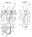
- a pipe unit 3 is fabricated having a large diameter pipe 1 and a small diameter pipe 2 as shown in Figure 3, and a blow molding machine 37 as shown in Figures 4-7 is employed.
- the blow molding machine 37 has two heads, i.e., a first head 4 and a second head 5.
- the blow molding machine in this particular embodiment molds a product having a single layer.
- First and second blow pins 14 and 16 respectively extend downward from the heads 4 and 5. These blow pins 14 and 16 are surrounded by first and second upper parison guides 22 and 23, respectively.
- a divisible molding die 39 is disposed including a first die element 6 and a second die element 7. As illustrated in Figure 5, the molding dies 6 and 7 contact each other at the convex plane 6a of the former and the concave plane 7a of the latter.
- the first hollow 8 has a diameter greater than the second hollow 9, so that a large diameter pipe or parent pipe will be molded in the first hollow 8 and a small diameter pipe or child pipe will be molded in the second hollow 9.
- Each hollow is defined by a couple of cavities which are semicircularly (in cross section) recessed into the contact planes 6a and 7a, respectively. Namely, the first hollow 8 is defined by cavities 8a and 8b, and the second hollow 9 is defined by cavities 9a and 9b.
- the upper parison guides 22 and 23 respectively extend from the bottoms of the heads 4 and 5 to the upper openings of the hollows 8 and 9, and respectively guide the parisons 14 and 16 supplied from the heads 4 and 5 to the hollows 8 and 9.
- the parisons 14 and 16 are made of light weight resin.
- Upper pinch members 18 and 19 are provided between the upper parison guides 22 and 23 and the top of the molding 39 for closing the upper openings of the hollows 8 and 9.
- the hollows 8 and 9 are formed in the molding 39 in a manner such that they approach each other at the middle thereof, at which a channel 34 is formed connecting the first hollow 8 with the second hollow 9.
- the channel 34 illustrated in Figures 5 and 6 is defined by a slot 11 formed in the first die element 6 and another slot 12 formed in the second die element 7.
- a recess 28 for molding a seat 29 ( Figure 3) is formed, to which one end 38 of the child pipe 2 will be coupled ( Figure 1 or 2).
- zigzag portions 10 are formed for molding bellows 31 ( Figure 1 or 2) as a part of the child pipe 2.
- the child pipe 2 will have a large flexibility at the bellows part.
- Lower pinch members 20 and 21 are provided at the bottom of the molding die 39 for opening/closing the lower ends of the hollows 8 and 9. Also at the bottom of the molding die 39 lower parison guides 24 and 25 are provided. A first and second blowers 26 and 27 are provided at the free ends of the lower parison guides 26 and 27, respectively, for applying suction forces to the parisons 15 and 17.
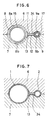
- a spacer 13 is put into the channel 31 so that the hollows 8 and 9 are independent from each other. Then the parisons 15 and 17 are supplied to the molding die 39.
- the blowers 26 and 27 start sucking in the first and second hollows 8 and 9 in order to help the parisons 15 and 17 to penetrate the hollows easily.
- the blowers 26 and 27 do not stop until the tips of the parisons 15 and 17 are pulled from the bottom of the molding die 39 by a predetermined length, respectively.
- the upper pinch members 18 and 19 as well as the lower pinch members 20 and 21 close the hollows 8 and 9.
- the first and second hollows 8 and 9 are still independent due to the spacer element 13 as shown in Figure 6.
- the parison 15 expands until it reaches the wall defined by the cavities 8a and 8b with the seat portion 29 ( Figure 3) being integrally formed therewith, thereby forming the parent pipe 1.
- the parison 17 is inflated until it reaches the wall defined by the cavities 9a and 9b as shown in Figure 7 with the bellows portion 31 ( Figure 3) being integrally formed therewith, thereby forming the child pipe 2.
- the parent and child pipes 1 and 2 are joined to each other by the spacer element 13 upon fusion of the parison. Therefore, a pipe unit 3 as illustrated in Figure 3 is fabricated, which has the large pipe 1 and the small pipe 2 coupled with the large pipe 1 by the intermediate member 13, all these elements being made of light resin.
- the thus obtained pipe unit 3 is cut at either end as indicated by the double-dotted line in Figure 3, so as to obtain the pipe unit 3 of a predetermined shape. Then, referring to Figure 1, the upper end 38 of the child pipe 2 is joined to a wall , i.e., the seat 29, of the parent pipe 1 near its top 36. Prior to this connection, an opening 30 (Figure 3) is made at the seat 29. The connection of the two pipes is depicted in a larger scale in Figure 2. The pipes 1 and 2 are joined by fusion at the plane 33.
- the pipe unit 3 shown in Figure 1 is for example used in the gasoline tank of an automobile.
- the gasoline flows into the tank through the pipe 1 while the air in the tank is expelled through the pipe 2, so that it is possible to smoothly fill in the gasoline.
- the spacer 13 may connect the pipes 1 and 2 at a position other than the middle of the pipes, two bellows 31 may be combined to form one element, and two or more channels may be formed.
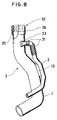
- an attachment 32 having a female thread may be attached to the upper end 36 of the parent pipe 1.
- the attachment 32 may be formed by means of injection molding.
- the attachment 32 may be joined with the pipe 1 by fusion.
- blow molding machine which can mold a product having a plurality of layers.
- one layer is made of resin and another layer is made of anticorrosion material.
- Figures 9 to 12 illustrate an example of a blow molding machine 137 for carrying out the method of this embodiment and Figure 13 illustrates a product 103.
- a multi-head blow molding machine 137 having a first head 104 and a second head 105 and a divisible molding die 139, like the first embodiment.
- a first couple of cavities 108a and 108b are symmetrically formed in first and second die elements 106 and 107, and a second couple of cavities 109a and 109b are formed likewise in the die elements 106 and 107 in a manner such that they define a first hollow 108 and a second hollow 109, respectively, when the two die elements are coupled with each other at a concave contact plane 106a of the first die element 106 and a convex contact plane 107a of the second die element 107.
- the shapes of the hollows 108 and 109 are determined by the configurations of the pipes 101 and 102.
- the first hollow 108 and the second hollow 109 are bent toward each other at the middle thereof, as shown in Figure 9, and two channels 134 are formed connecting the hollows 108 and 109.
- spacer elements 112 are provided as illustrated in Figure 11 in a manner such that the first and second hollows 108 and 109 are independent from each other.
- numeral 113 designates a first blow pin for feeding air to parison 114 supplied in the first hollow 108
- numeral 115 designates a second blow pin for feeding air to parison 116 supplied in the second hollow 109
- numerals 117 and 118 designate upper pinch members mounted on the top of the molding die 137 for cutting the parison and closing the upper openings of the hollows, respectively
- numerals 119 and 120 designate lower pinch members mounted on the bottom of the molding die 137 for closing the lower ends of the hollows
- numerals 121 and 122 are upper parison guides
- numerals 123 and 124 are lower parison guides for guiding the parisons 114 and 116 to/from the hollows respectively
- numerals 125 and 126 designate blowers for applying suction forces on the parisons 114 and 116, respectively.
- the parison 114 extruded from the first head 104 is introduced into the first hollow 108 through the guide 121.
- the parison 116 from the second head 105 is introduced into the second hollow 109 through the guide 122.
- the blowers 125 and 126 start applying suction forces to the parisons 114 and 116.
- the blowers 125 and 126 are stopped when the tips of the parisons 114 and 116 extend from the bottom of the molding die 139 by a predetermined length, respectively.
- the upper pinch members 117 and 118 as well as the lower pinch members 119 and 120 close the hollows 108 and 109, and the air blowing starts.
- the parisons 114 and 116 of Figure 11 are inflated to the pipes 101 and 102 of Figure 12.
- the parison 114 expands until it reaches the wall defined by the cavities 108a and 108b as the air is fed into the hollow 108, thereby forming the parent pipe 101.
- the parison 116 is inflated until it reaches the wall defined by the cavities 109a and 109b, thereby forming the child pipe 102.
- the parent and child pipes 101 and 102 are joined to each other via the spacer element 112 due to fusion of the parison 114 and 116. Therefore, a pipe unit 103 as illustrated in Figure 13 is fabricated, which includes the large pipe 101 and the small pipe 102 joined to each other by the intermediate member 112, all these elements being made of light resin.
- the thus obtained pipe unit 103 shown in Figure 13 is for example used in the gasoline tank of an automobile, as mentioned for the last embodiment.
- Figures 14 to 18 show one example thereof.
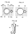
- three couples of slots 127 and 128 are formed in the molding die 139, whereby three channels 129 are defined.
- the length of the channel 129 in the modification is short as shown in Figure 16 or 17 as compared with the illustration of Figure 11 or 12, and that a spacer element is not provided in the channels. Therefore, the parison 114 in the first hollow 108 and the parison 116 in the second hollow 109 are forced into the channels 129 upon air blowing and joined with each other due to fusion of the parison, whereby the pipe unit 103 shown in Figure 18 is obtained.
- the same numerals are given to the same elements.
- the channels 129 may have a configuration other than the illustrated ones.
- the channel 129 is of course shaped in a manner such that the parisons 114 and 116 easily enter the passage 129, and the fusion of the parisons 114 and 116 is not affected.
- FIG. 19 to 22 illustrate an example of the blow molding machine 237 for carrying out the method of this embodiment which is very much similar to the molding machine of the foregoing embodiments.
- a multi-head molding machine 237 having a first head 204 and a second head 205 as well as a divisible molding die 239.
- a first couple of cavities 208a and 208b are symmetrically formed in the contact planes 206a and 207a of two die elements 206 and 207, respectively, and a second couple of cavities 209a and 209b are also formed in the contact planes 206a and 207a of the molding die elements 206 and 207, respectively, in a manner such that they define a first hollow 208 and a second hollow 209 as the divisible molding die elements 206 and 207 are joined with each other at a concave contact plane 206a and a convex contact plane 207a.
- the shapes of the hollows 208 and 209 i. e., the configuration of the curved surfaces of the contact planes 206a and 207a, are determined by the configurations of the pipes 201 and 202.
- the first hollow 208 and the second hollow 209 are bent toward each other at their middle section, as shown in Figure 19, and a channel 234 is formed connecting the hollows 208 and 209.
- a valve mechanism including a first valve 210 and a second valve 211 is provided. When the valves 210 and 211 are moved by respective actuators 212 and 213 toward each other until they meet, the first hollow 208 and the second hollow 209 become independent from each other as shown in Figures 20 and 21.
- numeral 214 designates a first blow pin for feeding air to parison 214 supplied to the first hollow 208
- numeral 216 designates a second blow pin for feeding air to parison 217 supplied to the second hollow 209
- numerals 218 and 219 designate upper pinch members mounted on the top of the molding die 237 for cutting the parisons 215 and 217 and for closing the upper openings of the hollows 208 and 209, respectively
- numerals 220 and 221 designate lower pinch members mounted on the bottom of the molding die 237 for closing the lower ends of the hollows 208 and 209, respectively
- numerals 222 and 223 are upper parison guides
- numeral 224 and 225 are lower parison guides for guiding the parisons 215 and 217 to/from the hollows 208 and 209, respectively
- numerals 226 and 227 designate blowers for applying suction forces on the parisons 215 and 217, respectively.
- the parison 215 extruded from the first head 204 is introduced into the first hollows 208.
- the parison 217 from the second head 205 is introduced into the second hollow 209.
- the blowers 226 and 227 start sucking the air out of the interior of the hollows 208 and 290 respectively.
- the blowers 226 and 227 are stopped when the parisons 215 and 217 are pulled out of the molding die 239 from its bottom by a predetermined length, respectively.
- the upper pinch members 218 and 219 close the upper openings of the hollows 208 and 209, respectively.
- the lower pinch members 220 and 221 close the lower openings of the hollows 208 and 209, respectively.
- the hollows 208 and 209 are separated from each other by the valves 210 and 211, as shown in Figure 21. Thereafter, the valves 210 and 211 are pulled back and the air blowing is started. Thereupon the parisons 215 and 217 of Figure 21 are inflated to the pipes 201 and 202 of Figure 22. Specifically, the parison 215 expands until it reaches the wall defined by the cavities 208a and 208b as the air is fed into the hollow 208, thereby forming a pipe 201 which is large in diameter. Likewise, the parison 217 is inflated until it reaches the wall defined by the cavities 209a and 209b, thereby forming another pipe 202 which is smaller in diameter than the pipe 201.
- FIG. 1 For example, another type of molding machine with more than two heads may be employed. If the molding machine has three heads, for example, a bundle-like pipe unit including three independent pipes can be molded. Also the pipes may be equal to each other in diameter or/and entire configuration.
Landscapes
- Engineering & Computer Science (AREA)
- Mechanical Engineering (AREA)
- Manufacturing & Machinery (AREA)
- Blow-Moulding Or Thermoforming Of Plastics Or The Like (AREA)
- Moulds For Moulding Plastics Or The Like (AREA)
Description
- The present invention generally relates to a method of fabricating a plurality of pipes for conveying fluid, for example those adapted for use in a gasoline tank of an automobile, and particularly to a method of fabricating a resin-made bundle-like pipe unit including a plurality of independent pipes joined with each other at their lateral walls.
- Generally, a pipe unit used as an inlet pipe of a gasoline tank of an automobile includes a large bore pipe (called "parent pipe") for conveying the gasoline and a small bore pipe (called "child pipe") for breathing. Usually, the child pipe is coupled with the parent pipe at one end, and these two pipes define a single pipe unit.
- Conventionally, the above-mentioned pipe units are made of metal, and manufactured by joining the child pipe with the parent pipe by means of brazing or spot welding at a part thereof and coupling the child pipe with the parent pipe at one end. However, this method has the following shortcomings.
- (1) The pipe unit is heavy in weight since each pipe is made from metal.
- (2) Many steps are required in manufacturing the pipe unit, so that it is difficult to lower the production cost.
- (3) The pipes might corrode since they are metallic.
- (4) When one end of the child pipe is coupled with the parent pipe, troublesome work is inevitable since the metallic pipes are not flexible.
- On the other hand, it is also known that two resin pipes are separately manufactured by means of blow molding and then joined with each other. One of the blow molding methods is disclosed in Japanese Patent Application Second Publication 47337/1983. In this reference, a parison is supplied from the molding machine and introduced into a hollow having a predetermined configuration made in the molding die. Then air is blown into the parison so as to inflate the parison. Accordingly, a single pipe which has the same configuration as the hollow formed in the molding die is blow-molded. However, in order to obtain a bundle-like pipe unit having a plurality of independent pipes, a plurality of pipes have to be molded separately, and then they are to be joined with each other.
- The problem to be solved by the invention is to provide a method of manufacturing a bundle-like pipe unit which is light in weight and requires less manufacturing steps, so that it is easy to carry out.
- The invention solves this problem by the features of the main claim. Further developments are specified in the subclaims.
- According to one aspect of the present invention, a method is provided using a blow molding machine employing a divisible molding die, having a couple of cavities (first cavities) in the respective contact planes of the die elements of the dividable molding die, which define a hollow (first hollow) in the molding die for manufacturing a parent pipe, having another couple of cavities (second cavities) in the same respective contact planes which define another hollow (second hollow) for manufacturing a child pipe, and having a couple of slots spanning the first and second cavities for defining a channel connecting the first hollow with the second hollow laterally, supplying a parison from the heads of the molding machine to the first and second hollows, and blowing air into the parison, so as to obtain a pipe unit including the parent pipe and the child pipe joined with the parent pipe at the lateral walls thereof.
- When the parison is introduced into the hollows of the molding die, suction forces are preferably applied to the parison from the downstream ends ("downstream" as viewed in the direction the parison moves) of the hollows in order to facilitate the penetration of the parison through the hollows. As the air blowing starts, the parison inside the hollows is inflated, so that the parent pipe having a large diameter is formed in the first hollow and the child pipe having a small diameter is formed in the second hollow. At the same time, the parison is forced into the channel connecting two hollows so that a part of the parent pipe is laterally joined with a part of the child pipe due to fusion. Therefore, a pipe unit is provided having a large diameter pipe and a small diameter pipe joined with the large pipe. The pipe unit has a large flexibility and is light in weight since it is made of resin.
- According to
claim 3, a couple of valve members are disposed in the channel connecting the first hollow with the second hollow before the parison is supplied to the hollows. The valve members are removed after the parison is introduced into the hollows. Then, the air blowing starts. The parisons are inflated in the hollows and almost simultaneously pushed into the channel, whereby the two pipes are joined with each other by the parison. - According to claim 4, a spacer element is disposed in the channel connecting the first and second hollows prior to the air blowing. The parent pipe is joined with the child pipe via the spacer element.
- These and other aspects, objects and advantages of the present invention will be more fully understood by reference to the following detailed description taken in conjunction with the various figures and appended claims.
- Figure 1
- is a perspective view of a pipe unit obtained from a first embodiment of the present invention;
- Figure 2
- is an enlarged view of part "I" of Figure 1;
- Figure 3
- is a perspective view showing a pipe unit obtained immediately after the blow molding in the first embodiment;
- Figure 4
- is a front sectional view of a blow molding machine used in the first embodiment;
- Figure 5
- is a view taken along the line II-II of Figure 4;
- Figure 6
- is a view taken along the line III-III of Figure 4 when the parison is introduced into a first and second hollows;
- Figure 7
- is a view taken along the line III-III of Figure 4 as the air blowing starts;
- Figure 8
- is a perspective view showing a pipe unit obtained from a modification of the first embodiment;
- Figure 9
- is a front sectional view of a blow molding machine used in a second embodiment of the present invention;
- Figure 10
- is a view taken along the line IV-IV of Figure 9;
- Figure 11
- is a view taken along the line V-V of Figure 9 when the parison is introduced into first and second hollows;
- Figure 12
- is a view taken along the line V-V of Figure 9 as the air blowing starts;
- Figure 13
- is a perspective view showing a pipe unit obtained from the second embodiment of the present invention;
- Figure 14
- is a sectional view of a blow molding machine used in the second embodiment;
- Figure 15
- is a lateral view of Figure 14;
- Figure 16
- is a view taken along the line VI-VI of Figure 14 when the parison is introduced into first and second hollows;
- Figure 17
- is a view taken along the line VI-VI of Figure 9 as the air blowing starts;
- Figure 18
- is a perspective view showing a pipe unit obtained from a modification of the second embodiment of the present invention;
- Figure 19
- is a front sectional view of a blow molding machine used in a third embodiment of the present invention;
- Figure 20
- is a view taken along the line IIX-IIX of Figure 19;
- Figure 21
- is a view taken along the line VII-VII of Figure 19 when the parison is introduced into first and second hollows;
- Figure 22
- is a view taken along the line VII-VII of Figure 19 as the blow molding starts; and
- Figure 23
- is a perspective view showing a pipe unit obtained from the third embodiment of the present invention.
- A first embodiment of the present invention will be described with reference to Figures 1-7 of the accompanying drawings. In this embodiment, a
pipe unit 3 is fabricated having alarge diameter pipe 1 and asmall diameter pipe 2 as shown in Figure 3, and ablow molding machine 37 as shown in Figures 4-7 is employed. - Referring to Figures 4 and 5, the
blow molding machine 37 has two heads, i.e., a first head 4 and asecond head 5. The blow molding machine in this particular embodiment molds a product having a single layer. First and second blow pins 14 and 16 respectively extend downward from theheads 4 and 5. These blow pins 14 and 16 are surrounded by first and second upper parison guides 22 and 23, respectively. Below the heads 4 and 5 a divisible molding die 39 is disposed including afirst die element 6 and asecond die element 7. As illustrated in Figure 5, the molding dies 6 and 7 contact each other at theconvex plane 6a of the former and theconcave plane 7a of the latter. - Two passages or
hollows cavities cavities - The upper parison guides 22 and 23 respectively extend from the bottoms of the
heads 4 and 5 to the upper openings of thehollows parisons heads 4 and 5 to thehollows parisons Upper pinch members molding 39 for closing the upper openings of thehollows - As shown in Figure 4, the
hollows molding 39 in a manner such that they approach each other at the middle thereof, at which achannel 34 is formed connecting the first hollow 8 with the second hollow 9. Thechannel 34 illustrated in Figures 5 and 6 is defined by aslot 11 formed in thefirst die element 6 and anotherslot 12 formed in thesecond die element 7. - Near the upper end of the first hollow 8 a
recess 28 for molding a seat 29 (Figure 3) is formed, to which oneend 38 of thechild pipe 2 will be coupled (Figure 1 or 2). On the other hand, near the upper end of the second hollow 9,zigzag portions 10 are formed for molding bellows 31 (Figure 1 or 2) as a part of thechild pipe 2. Thechild pipe 2 will have a large flexibility at the bellows part. -
Lower pinch members hollows second blowers parisons - Before the
parisons heads 4 and 5 of themolding machine 37, respectively, aspacer 13 is put into thechannel 31 so that thehollows parisons blowers second hollows parisons blowers parisons upper pinch members lower pinch members hollows second hollows spacer element 13 as shown in Figure 6. As the air is fed into the hollow 8 from theblow pin 14 as shown in Figure 7, theparison 15 expands until it reaches the wall defined by thecavities parent pipe 1. Likewise, theparison 17 is inflated until it reaches the wall defined by thecavities child pipe 2. At the same time, the parent andchild pipes spacer element 13 upon fusion of the parison. Therefore, apipe unit 3 as illustrated in Figure 3 is fabricated, which has thelarge pipe 1 and thesmall pipe 2 coupled with thelarge pipe 1 by theintermediate member 13, all these elements being made of light resin. - The thus obtained
pipe unit 3 is cut at either end as indicated by the double-dotted line in Figure 3, so as to obtain thepipe unit 3 of a predetermined shape. Then, referring to Figure 1, theupper end 38 of thechild pipe 2 is joined to a wall , i.e., theseat 29, of theparent pipe 1 near its top 36. Prior to this connection, an opening 30 (Figure 3) is made at theseat 29. The connection of the two pipes is depicted in a larger scale in Figure 2. Thepipes plane 33. - The
pipe unit 3 shown in Figure 1 is for example used in the gasoline tank of an automobile. When the gasoline is filled into the tank, the gasoline flows into the tank through thepipe 1 while the air in the tank is expelled through thepipe 2, so that it is possible to smoothly fill in the gasoline. - Various modifications of the illustrated embodiment are possible. For instance, the
spacer 13 may connect thepipes bellows 31 may be combined to form one element, and two or more channels may be formed. - Also, as shown in Figure 8, an
attachment 32 having a female thread may be attached to theupper end 36 of theparent pipe 1. Theattachment 32 may be formed by means of injection molding. Theattachment 32 may be joined with thepipe 1 by fusion. - In addition, another type of blow molding machine may be employed which can mold a product having a plurality of layers. In this case, for example, one layer is made of resin and another layer is made of anticorrosion material.
- A second embodiment will be described with reference to Figures 9 to 18. Figures 9 to 12 illustrate an example of a
blow molding machine 137 for carrying out the method of this embodiment and Figure 13 illustrates aproduct 103. - Referring to Figures 9 and 10, a multi-head
blow molding machine 137 is employed having afirst head 104 and asecond head 105 and a divisible molding die 139, like the first embodiment. A first couple ofcavities elements cavities die elements concave contact plane 106a of thefirst die element 106 and aconvex contact plane 107a of thesecond die element 107. The shapes of thehollows pipes channels 134 are formed connecting thehollows channels 134spacer elements 112 are provided as illustrated in Figure 11 in a manner such that the first andsecond hollows parison 114 supplied in the first hollow 108, numeral 115 designates a second blow pin for feeding air toparison 116 supplied in the second hollow 109,numerals numerals numerals numerals parisons numerals parisons - The
parison 114 extruded from thefirst head 104 is introduced into the first hollow 108 through theguide 121. Likewise, theparison 116 from thesecond head 105 is introduced into the second hollow 109 through theguide 122. At the same time, theblowers parisons blowers parisons upper pinch members lower pinch members hollows parisons pipes parison 114 expands until it reaches the wall defined by thecavities parent pipe 101. Likewise, theparison 116 is inflated until it reaches the wall defined by thecavities child pipe 102. At the same time, the parent andchild pipes spacer element 112 due to fusion of theparison pipe unit 103 as illustrated in Figure 13 is fabricated, which includes thelarge pipe 101 and thesmall pipe 102 joined to each other by theintermediate member 112, all these elements being made of light resin. - The thus obtained
pipe unit 103 shown in Figure 13 is for example used in the gasoline tank of an automobile, as mentioned for the last embodiment. - Various modifications of the illustrated embodiment are possible, and Figures 14 to 18 show one example thereof. Referring to Figures 14 and 15, three couples of
slots channels 129 are defined. Here it should be noted that the length of thechannel 129 in the modification is short as shown in Figure 16 or 17 as compared with the illustration of Figure 11 or 12, and that a spacer element is not provided in the channels. Therefore, theparison 114 in the first hollow 108 and theparison 116 in the second hollow 109 are forced into thechannels 129 upon air blowing and joined with each other due to fusion of the parison, whereby thepipe unit 103 shown in Figure 18 is obtained. In Figures 9 to 18, the same numerals are given to the same elements. - In addition, the
channels 129 may have a configuration other than the illustrated ones. In this case thechannel 129 is of course shaped in a manner such that theparisons passage 129, and the fusion of theparisons - A third embodiment will be described with reference to Figures 19 to 23. Figures 19 to 22 illustrate an example of the
blow molding machine 237 for carrying out the method of this embodiment which is very much similar to the molding machine of the foregoing embodiments. - Referring to Figures 19 and 20, a
multi-head molding machine 237 is illustrated having afirst head 204 and asecond head 205 as well as a divisible molding die 239. A first couple ofcavities contact planes elements cavities contact planes elements elements concave contact plane 206a and aconvex contact plane 207a. The shapes of thehollows 208 and 209, i. e., the configuration of the curved surfaces of thecontact planes pipes channel 234 is formed connecting thehollows 208 and 209. In order to close thechannel 234, a valve mechanism including afirst valve 210 and asecond valve 211 is provided. When thevalves respective actuators - Returning to Figures 19 and 20, numeral 214 designates a first blow pin for feeding air to
parison 214 supplied to the first hollow 208, numeral 216 designates a second blow pin for feeding air toparison 217 supplied to the second hollow 209,numerals parisons hollows 208 and 209, respectively,numerals hollows 208 and 209, respectively,numerals parisons hollows 208 and 209, respectively, andnumerals parisons - The
parison 215 extruded from thefirst head 204 is introduced into the first hollows 208. Likewise, theparison 217 from thesecond head 205 is introduced into the second hollow 209. At the same time, theblowers blowers parisons upper pinch members hollows 208 and 209, respectively. Likewise, thelower pinch members hollows 208 and 209, respectively. Until then, thehollows 208 and 209 are separated from each other by thevalves valves parisons pipes parison 215 expands until it reaches the wall defined by thecavities pipe 201 which is large in diameter. Likewise, theparison 217 is inflated until it reaches the wall defined by thecavities pipe 202 which is smaller in diameter than thepipe 201. At the same time, thesepipes parisons passage 234. Therefore, when the molding dies 206 and 207 are separated from each other, apipe unit 203 is obtained as illustrated in Figure 23, which includes alarge diameter pipe 201 and asmall diameter pipe 202 directly joined with thelarge pipe 201. - Various modifications of the illustrated embodiment are possible. For example, another type of molding machine with more than two heads may be employed. If the molding machine has three heads, for example, a bundle-like pipe unit including three independent pipes can be molded. Also the pipes may be equal to each other in diameter or/and entire configuration.
Claims (7)
- A method of fabricating a pipe unit (3;103;203), using a blow molding machine (37;137;237) having a plurality of heads (4,5;104,105;204,205) which feed parisons (14,16;114,116;215,217), respectively, the method comprising the steps of:
using a molding die (39;139;239) of the blow molding machine (37;137;237) having a plurality of hollows (8, 9; 108,109; 208,209) and
one or more channels (34;129;134;234) connecting the hollows (8,9;108,109;208,209) to each other laterally;
feeding the parisons (15,17;114,116;215,217) into the hollows (8,9;108,109;208,209) from the heads (4,5;104,105;204,205) of the blow molding machine (37;137;237); and
blowing air into the parisons (15,17;114,116;215,217) in a manner such that a plurality of independent pipes (1,2; 101,102;201,202) are molded in the respective hollows (8,9; 108,109;208,209) and that the pipes (1,2;101,102;201,202) are joined to each other at the lateral walls thereof by the parisons which are forced into the channels (34;129;134;234). - The method of claim 1, characterized by using a blow molding machine (37;137;237) having two heads (4,5;104,105;204,205) and a single, divisible molding die (39;139;239) including two die elements (6,7;106,107;206,207),
two couples of cavities (8a,8b,9a,9b;108a,108b, 109a,109b;208a,208b,209a,209b) of different configuration in the die elements (6,7;106,107;206,207), respectively, in a manner such that two cylinder-like hollows (8,9;108,109;208,209) are defined, one of which (8;108;208) being larger than the other (9;109;209) in diameter, when the die elements (6,7;106,107;206,207) are joined to form the single die (39;139;239);
and one or more couples of slots (11,12;110,111;127,128) in the die elements (6,7;106,107), respectively, in a manner such that they define one or more channels (34;129;134;234) connecting the hollows (8,9;108,109;208,209) to each other laterally when the die elements (6,7;106,107;206,207) are joined to form the single die (39;139;239). - The method of fabricating a pipe unit (3;103;203) according to claim 1 or 2, characterized in that the method further comprises the steps of:
providing partition valve means (210,211) in the channels (34;129;134;234) prior to the step of feeding the parisons (14,16;114,116;215;217); and
removing the partition valve means (210,211) after the step of feeding the parisons. - The method of fabricating a pipe unit (3;103;203) according to claim 1 or 2, characterized in that the method further comprises the step of:
providing spacer elements (13;112) in the channels (34;129;134) prior to the step of feeding the parisons (15,17;114,116;215,217), so as to mold a bundle - like pipe unit (3,103,203) which has a plurality of independent pipes (1,2;101,102;201,202) joined with each other via the spacer elements (13;112) at the lateral parts thereof. - The method of fabricating a pipe unit (3;103;203) according to one of claims 1 to 4, characterized in that the method further comprises the step of:
applying suction force on the parisons (14,16;114,116; 215,217) when the parisons are fed into the hollows (8,9;108,109;208,209). - The method of fabricating a pipe unit (3;103;203) according to one of claims 1 to 5, characterized in that the method further comprises the step of:
forming in one couple of cavities (9a,9b) one ore more couples of annular recesses (10) each being V-shaped in cross section, prior to the step of feeding the parisons (15,17;114,116;215,217) in a manner such that one pipe (2) of the pipe unit (3) has a bellows part (31). - The method of fabricating a pipe unit (3;103;203) according to one of claims 2 to 6, characterized in that the method further comprises the steps of:
separating the die elements (6,7;106,107;206,207) from each other after feeding the parisons (15,17;114,116;215,217);
forming an opening (30) in the pipe having a larger diameter (1); and
joining one free end (38) of the smaller pipe (2) to the opening (30) formed in the larger pipe (1) by fusion.
Applications Claiming Priority (6)
| Application Number | Priority Date | Filing Date | Title |
|---|---|---|---|
| JP234554/88 | 1988-09-19 | ||
| JP23455488 | 1988-09-19 | ||
| JP24739188 | 1988-10-03 | ||
| JP247391/88 | 1988-10-03 | ||
| JP25189388 | 1988-10-07 | ||
| JP251893/88 | 1988-10-07 |
Publications (3)
| Publication Number | Publication Date |
|---|---|
| EP0360220A2 EP0360220A2 (en) | 1990-03-28 |
| EP0360220A3 EP0360220A3 (en) | 1990-12-12 |
| EP0360220B1 true EP0360220B1 (en) | 1994-06-01 |
Family
ID=27332156
Family Applications (1)
| Application Number | Title | Priority Date | Filing Date |
|---|---|---|---|
| EP89117303A Expired - Lifetime EP0360220B1 (en) | 1988-09-19 | 1989-09-19 | Method of fabricating pipe units |
Country Status (4)
| Country | Link |
|---|---|
| US (1) | US5049224A (en) |
| EP (1) | EP0360220B1 (en) |
| CA (1) | CA1328550C (en) |
| DE (1) | DE68915664T2 (en) |
Families Citing this family (19)
| Publication number | Priority date | Publication date | Assignee | Title |
|---|---|---|---|---|
| JPH0538769A (en) * | 1991-07-19 | 1993-02-19 | Mitsutoyo Jushi Kk | Injection molding a thick flange on the end of a blow molded tube |
| EP0550776B1 (en) * | 1992-01-10 | 1997-04-09 | Excell Corporation | Method for producing a hollow plastic product having a radially extending portion |
| ES2108980T3 (en) * | 1993-02-04 | 1998-01-01 | Baxter Int | SET OF ELONGATED PLASTIC ELEMENTS AND PROCEDURE AND DEVICE FOR ITS REALIZATION. |
| US5840151A (en) * | 1993-02-04 | 1998-11-24 | Baxter International Inc. | Apparatus and dies for forming peelable tube assemblies |
| US5776518A (en) * | 1995-05-16 | 1998-07-07 | Ultraseal Technologies Corporation | Bottle mold and adjustable top block assembly and top block alignment members |
| FR2746339B1 (en) * | 1996-03-22 | 1998-06-05 | Plastic Omnium Cie | METHOD FOR MANUFACTURING A BEAM OF ATTACHED TUBES, DEVICE FOR CARRYING OUT SUCH A METHOD AND BEAM THUS PRODUCED |
| US5996639A (en) * | 1997-01-30 | 1999-12-07 | Action Technology | Multiple compartment corrugated hose |
| US6730322B1 (en) | 1998-04-30 | 2004-05-04 | Acusphere, Inc. | Matrices formed of polymer and hydrophobic compounds for use in drug delivery |
| US6423345B2 (en) | 1998-04-30 | 2002-07-23 | Acusphere, Inc. | Matrices formed of polymer and hydrophobic compounds for use in drug delivery |
| AP1304A (en) * | 1999-06-30 | 2004-09-09 | Byun Moo Won | Apparatus for producing multiple channel duct assembly and method thereof. |
| WO2001043940A1 (en) * | 1999-12-17 | 2001-06-21 | Cooper Tire & Rubber Company | Tube product with molded on bracket |
| US6432345B1 (en) * | 1999-12-29 | 2002-08-13 | Truseal Usa, Inc. | Single-step method of manufacturing a silicone tube manifold |
| US6355204B1 (en) | 2000-06-07 | 2002-03-12 | Owens-Brockway Plastic Products Inc. | Method of manufacturing a dual-chamber container |
| DE10158663C1 (en) * | 2001-11-30 | 2003-05-08 | Siemens Ag | Production of branched plastic pipes comprises filling mold with plastic and then blow-molding to produce bores, bore in branch being produced by plug of plastic which is removed as main bore is blow molded |
| WO2004022433A2 (en) * | 2002-09-03 | 2004-03-18 | Clean Cut Technologies, Llc | Apparatus and method for packaging elongate surgical devices |
| JP2004351658A (en) * | 2003-05-27 | 2004-12-16 | Toyoda Gosei Co Ltd | Method of manufacturing branch pipe |
| EP1830118A1 (en) * | 2006-03-03 | 2007-09-05 | GEPOC Verfahrenstechnik GmbH | Multi-tube hose |
| US20070261752A1 (en) * | 2006-04-13 | 2007-11-15 | Stant Manufacturing Inc. | Multiple-layer fluid fuel apparatus |
| ES2401617B1 (en) * | 2011-08-05 | 2014-04-01 | Fundació Privada Ascamm | Procedure for the manufacture of air ducts of plastic material and mold used |
Family Cites Families (10)
| Publication number | Priority date | Publication date | Assignee | Title |
|---|---|---|---|---|
| CH481738A (en) * | 1968-08-06 | 1969-11-30 | Proplasto Ag | Method and mold for manufacturing a multi-compartment container |
| US3636151A (en) * | 1970-04-27 | 1972-01-18 | Kyoraku Kogyo Co Ltd | Method for producing a hollow doublewall plastic article |
| JPS4933348A (en) * | 1972-08-07 | 1974-03-27 | ||
| US4086937A (en) * | 1976-08-06 | 1978-05-02 | Hechler Iv Valentine | Dual hose |
| US4280859A (en) * | 1978-02-14 | 1981-07-28 | Thompson Mortimer S | Method of manufacturing a blow-molded container with an integral handle |
| JPS55161623A (en) * | 1979-06-05 | 1980-12-16 | Nippon Radiator Co Ltd | Manufacture of plastic complex tank |
| JPS58124622A (en) * | 1982-01-20 | 1983-07-25 | Keigo Tanemoto | Hollow forming method of spherical body |
| JPS58126121A (en) * | 1982-01-22 | 1983-07-27 | Nippon Plast Co Ltd | Manufacture of blow-molded product |
| JPS5942936A (en) * | 1982-09-04 | 1984-03-09 | Sanshin Kako Kk | Blow molding method |
| WO1987001330A1 (en) * | 1985-08-30 | 1987-03-12 | Garwood Ltd. | Improved tray for packaging |
-
1989
- 1989-09-18 CA CA000611710A patent/CA1328550C/en not_active Expired - Fee Related
- 1989-09-19 US US07/409,209 patent/US5049224A/en not_active Expired - Lifetime
- 1989-09-19 DE DE68915664T patent/DE68915664T2/en not_active Expired - Fee Related
- 1989-09-19 EP EP89117303A patent/EP0360220B1/en not_active Expired - Lifetime
Also Published As
| Publication number | Publication date |
|---|---|
| CA1328550C (en) | 1994-04-19 |
| DE68915664T2 (en) | 1995-01-12 |
| EP0360220A2 (en) | 1990-03-28 |
| US5049224A (en) | 1991-09-17 |
| EP0360220A3 (en) | 1990-12-12 |
| DE68915664D1 (en) | 1994-07-07 |
Similar Documents
| Publication | Publication Date | Title |
|---|---|---|
| EP0360220A2 (en) | Method of fabricating pipe units | |
| AU598343B2 (en) | A method and an apparatus for the extrusion of plastic pipes | |
| EP1981694B1 (en) | Method for producing a plastic hollow body | |
| KR930004168B1 (en) | Double-walled tube assembly and method of continuously manufacturing the same | |
| US5932166A (en) | Method and apparatus for manufacturing joined tubes | |
| US5171044A (en) | Pipe unit | |
| JP3675864B2 (en) | Blow molding method and apparatus | |
| EP0550776B1 (en) | Method for producing a hollow plastic product having a radially extending portion | |
| CN1539623B (en) | Blowing injection moulded vessel with holes and method of and appts. for such vessel | |
| EP0886608B1 (en) | Cable tie bandoliers for use with automatic tools | |
| JPH06126812A (en) | Blow molding method and device | |
| JP2959207B2 (en) | Blow molding method of parent-child pipe | |
| JP3809658B2 (en) | Blow molding apparatus for boot and method for manufacturing the same | |
| JP3566376B2 (en) | Manufacturing method of hollow plate | |
| US4734244A (en) | Blow molding method and mold with means to position an insert | |
| JPH05208428A (en) | Manufacture of composite synthetic resin molded body | |
| JPH01283125A (en) | Blow molding method of integral molding of trimming part | |
| JP3241490B2 (en) | Method for producing resin tubular body | |
| JP3654676B2 (en) | Manufacturing method of door trim | |
| JPH0622866B2 (en) | Method for producing plastic hollow body | |
| JP3774416B2 (en) | Method for molding multilayer hollow body made of synthetic resin having blow molded inner layer | |
| JP3706406B2 (en) | Blow molded panel manufacturing method and manufacturing mold thereof | |
| JPS61148034A (en) | Molding method of resin product | |
| JPH02243323A (en) | Manufacturing method for fluid feeding pipe | |
| WO1992014599A1 (en) | Blow moulding method |
Legal Events
| Date | Code | Title | Description |
|---|---|---|---|
| PUAI | Public reference made under article 153(3) epc to a published international application that has entered the european phase |
Free format text: ORIGINAL CODE: 0009012 |
|
| AK | Designated contracting states |
Kind code of ref document: A2 Designated state(s): AT BE CH DE ES FR GB GR IT LI LU NL SE |
|
| RBV | Designated contracting states (corrected) |
Designated state(s): DE FR SE |
|
| PUAL | Search report despatched |
Free format text: ORIGINAL CODE: 0009013 |
|
| AK | Designated contracting states |
Kind code of ref document: A3 Designated state(s): AT BE CH DE ES FR GB GR IT LI LU NL SE |
|
| 17P | Request for examination filed |
Effective date: 19910222 |
|
| 17Q | First examination report despatched |
Effective date: 19921120 |
|
| GRAA | (expected) grant |
Free format text: ORIGINAL CODE: 0009210 |
|
| AK | Designated contracting states |
Kind code of ref document: B1 Designated state(s): DE FR SE |
|
| REF | Corresponds to: |
Ref document number: 68915664 Country of ref document: DE Date of ref document: 19940707 |
|
| ET | Fr: translation filed | ||
| EAL | Se: european patent in force in sweden |
Ref document number: 89117303.1 |
|
| PLBE | No opposition filed within time limit |
Free format text: ORIGINAL CODE: 0009261 |
|
| STAA | Information on the status of an ep patent application or granted ep patent |
Free format text: STATUS: NO OPPOSITION FILED WITHIN TIME LIMIT |
|
| 26N | No opposition filed | ||
| PGFP | Annual fee paid to national office [announced via postgrant information from national office to epo] |
Ref country code: SE Payment date: 20040906 Year of fee payment: 16 |
|
| PGFP | Annual fee paid to national office [announced via postgrant information from national office to epo] |
Ref country code: FR Payment date: 20040908 Year of fee payment: 16 |
|
| PGFP | Annual fee paid to national office [announced via postgrant information from national office to epo] |
Ref country code: DE Payment date: 20040916 Year of fee payment: 16 |
|
| PG25 | Lapsed in a contracting state [announced via postgrant information from national office to epo] |
Ref country code: SE Free format text: LAPSE BECAUSE OF NON-PAYMENT OF DUE FEES Effective date: 20050920 |
|
| PG25 | Lapsed in a contracting state [announced via postgrant information from national office to epo] |
Ref country code: DE Free format text: LAPSE BECAUSE OF NON-PAYMENT OF DUE FEES Effective date: 20060401 |
|
| EUG | Se: european patent has lapsed | ||
| PG25 | Lapsed in a contracting state [announced via postgrant information from national office to epo] |
Ref country code: FR Free format text: LAPSE BECAUSE OF NON-PAYMENT OF DUE FEES Effective date: 20060531 |
|
| REG | Reference to a national code |
Ref country code: FR Ref legal event code: ST Effective date: 20060531 |