EP0360210B1 - Control apparatus and method for controlling an inverter for driving AC motor - Google Patents
Control apparatus and method for controlling an inverter for driving AC motor Download PDFInfo
- Publication number
- EP0360210B1 EP0360210B1 EP89117283A EP89117283A EP0360210B1 EP 0360210 B1 EP0360210 B1 EP 0360210B1 EP 89117283 A EP89117283 A EP 89117283A EP 89117283 A EP89117283 A EP 89117283A EP 0360210 B1 EP0360210 B1 EP 0360210B1
- Authority
- EP
- European Patent Office
- Prior art keywords
- motor
- frequency
- current
- sampling
- control apparatus
- Prior art date
- Legal status (The legal status is an assumption and is not a legal conclusion. Google has not performed a legal analysis and makes no representation as to the accuracy of the status listed.)
- Expired - Lifetime
Links
- 238000000034 method Methods 0.000 title description 3
- 238000005070 sampling Methods 0.000 claims description 46
- 230000002159 abnormal effect Effects 0.000 claims description 24
- 230000033764 rhythmic process Effects 0.000 claims 1
- 238000010586 diagram Methods 0.000 description 17
- 239000013598 vector Substances 0.000 description 12
- 230000004907 flux Effects 0.000 description 4
- 230000006698 induction Effects 0.000 description 4
- 238000001228 spectrum Methods 0.000 description 3
- 230000010354 integration Effects 0.000 description 2
- 238000004804 winding Methods 0.000 description 2
- 230000005856 abnormality Effects 0.000 description 1
- 150000001875 compounds Chemical class 0.000 description 1
- 239000012141 concentrate Substances 0.000 description 1
- 239000004020 conductor Substances 0.000 description 1
- 230000003247 decreasing effect Effects 0.000 description 1
- 230000000694 effects Effects 0.000 description 1
- 230000002349 favourable effect Effects 0.000 description 1
- 230000001360 synchronised effect Effects 0.000 description 1
Images




Classifications
-
- H—ELECTRICITY
- H02—GENERATION; CONVERSION OR DISTRIBUTION OF ELECTRIC POWER
- H02M—APPARATUS FOR CONVERSION BETWEEN AC AND AC, BETWEEN AC AND DC, OR BETWEEN DC AND DC, AND FOR USE WITH MAINS OR SIMILAR POWER SUPPLY SYSTEMS; CONVERSION OF DC OR AC INPUT POWER INTO SURGE OUTPUT POWER; CONTROL OR REGULATION THEREOF
- H02M7/00—Conversion of AC power input into DC power output; Conversion of DC power input into AC power output
- H02M7/42—Conversion of DC power input into AC power output without possibility of reversal
- H02M7/44—Conversion of DC power input into AC power output without possibility of reversal by static converters
- H02M7/48—Conversion of DC power input into AC power output without possibility of reversal by static converters using discharge tubes with control electrode or semiconductor devices with control electrode
- H02M7/53—Conversion of DC power input into AC power output without possibility of reversal by static converters using discharge tubes with control electrode or semiconductor devices with control electrode using devices of a triode or transistor type requiring continuous application of a control signal
- H02M7/537—Conversion of DC power input into AC power output without possibility of reversal by static converters using discharge tubes with control electrode or semiconductor devices with control electrode using devices of a triode or transistor type requiring continuous application of a control signal using semiconductor devices only, e.g. single switched pulse inverters
- H02M7/5387—Conversion of DC power input into AC power output without possibility of reversal by static converters using discharge tubes with control electrode or semiconductor devices with control electrode using devices of a triode or transistor type requiring continuous application of a control signal using semiconductor devices only, e.g. single switched pulse inverters in a bridge configuration
- H02M7/53871—Conversion of DC power input into AC power output without possibility of reversal by static converters using discharge tubes with control electrode or semiconductor devices with control electrode using devices of a triode or transistor type requiring continuous application of a control signal using semiconductor devices only, e.g. single switched pulse inverters in a bridge configuration with automatic control of output voltage or current
- H02M7/53873—Conversion of DC power input into AC power output without possibility of reversal by static converters using discharge tubes with control electrode or semiconductor devices with control electrode using devices of a triode or transistor type requiring continuous application of a control signal using semiconductor devices only, e.g. single switched pulse inverters in a bridge configuration with automatic control of output voltage or current with digital control
-
- H—ELECTRICITY
- H02—GENERATION; CONVERSION OR DISTRIBUTION OF ELECTRIC POWER
- H02M—APPARATUS FOR CONVERSION BETWEEN AC AND AC, BETWEEN AC AND DC, OR BETWEEN DC AND DC, AND FOR USE WITH MAINS OR SIMILAR POWER SUPPLY SYSTEMS; CONVERSION OF DC OR AC INPUT POWER INTO SURGE OUTPUT POWER; CONTROL OR REGULATION THEREOF
- H02M7/00—Conversion of AC power input into DC power output; Conversion of DC power input into AC power output
- H02M7/42—Conversion of DC power input into AC power output without possibility of reversal
- H02M7/44—Conversion of DC power input into AC power output without possibility of reversal by static converters
- H02M7/48—Conversion of DC power input into AC power output without possibility of reversal by static converters using discharge tubes with control electrode or semiconductor devices with control electrode
- H02M7/53—Conversion of DC power input into AC power output without possibility of reversal by static converters using discharge tubes with control electrode or semiconductor devices with control electrode using devices of a triode or transistor type requiring continuous application of a control signal
- H02M7/537—Conversion of DC power input into AC power output without possibility of reversal by static converters using discharge tubes with control electrode or semiconductor devices with control electrode using devices of a triode or transistor type requiring continuous application of a control signal using semiconductor devices only, e.g. single switched pulse inverters
- H02M7/5387—Conversion of DC power input into AC power output without possibility of reversal by static converters using discharge tubes with control electrode or semiconductor devices with control electrode using devices of a triode or transistor type requiring continuous application of a control signal using semiconductor devices only, e.g. single switched pulse inverters in a bridge configuration
- H02M7/53871—Conversion of DC power input into AC power output without possibility of reversal by static converters using discharge tubes with control electrode or semiconductor devices with control electrode using devices of a triode or transistor type requiring continuous application of a control signal using semiconductor devices only, e.g. single switched pulse inverters in a bridge configuration with automatic control of output voltage or current
- H02M7/53875—Conversion of DC power input into AC power output without possibility of reversal by static converters using discharge tubes with control electrode or semiconductor devices with control electrode using devices of a triode or transistor type requiring continuous application of a control signal using semiconductor devices only, e.g. single switched pulse inverters in a bridge configuration with automatic control of output voltage or current with analogue control of three-phase output
- H02M7/53876—Conversion of DC power input into AC power output without possibility of reversal by static converters using discharge tubes with control electrode or semiconductor devices with control electrode using devices of a triode or transistor type requiring continuous application of a control signal using semiconductor devices only, e.g. single switched pulse inverters in a bridge configuration with automatic control of output voltage or current with analogue control of three-phase output based on synthesising a desired voltage vector via the selection of appropriate fundamental voltage vectors, and corresponding dwelling times
Definitions
- the present invention relates to a control method and a control apparatus for controlling an inverter for driving an AC motor, which are particularly capable of effectively using electromagnetic vibration tones, i.e., noises generated from an AC motor such as an induction motor or a synchronous motor driven by a PWM inverter.
- this abnormal state Upon occurrence of overcurrent, overspeed or abnormal state in a motor, this abnormal state is generally detected and displayed on a display device or informed of by means of an alarm device.
- An object of the present invention is to make electromagnetic vibration tones generated by an AC motor nonoffensive to the ear.
- Another object of the present invention is to inform of an abnormal state or the like of an AC motor by using electromagnetic vibration tones generated from the AC motor.
- the electromagnetic tone generated from the motor serves as an information tone, and it becomes nonoffensive to the ear and can be used as an alarm tone or the like.
- Fig. 1 is a circuit configuration diagram of a control apparatus of an inverter for driving an AC motor according to an embodiment of the present invention.
- Fig. 2 is a circuit configuration diagram of an inverter section.
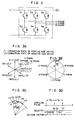
- Figs. 3A to 3D are diagrams for illustrating the operation of the inverter section.
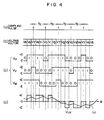
- Fig. 4 is a waveform diagram showing sampling pulses, voltage vectors, output voltage and output current.
- Fig. 5 is a diagram for illustrating the operation caused when an abnormal running state occurs.
- Fig. 6 is a diagram for illustrating contents of a data table.
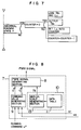
- Fig. 7 is a flow chart for illustrating contents of processing performed when an abnormal running state occurs.
- Fig. 8 is a configuration diagram of a control circuit showing another embodiment.
- Fig. 9 is a diagram showing relationship between musical interval and frequency.
- Fig. 10 is a characteristic diagram showing power spectrum distribution with respect to tone frequency.
- Figs. 11 to 15 are diagrams showing other embodiments.
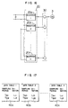
- Figs. 16 to 18 are configuration diagrams showing the case where the present invention is applied to a multi-inverter apparatus.
- Fig. 1 is a circuit configuration diagram of a control apparatus of an inverter for driving an AC motor according to an embodiment of the present invention.
- numeral 1 denotes a commercial three-phase AC power source
- numeral 2 denotes an inverter apparatus comprising an inverter section 2a and a converter section 2b.
- This inverter apparatus 2 is supplied with the output of the commercial three-phase AC power source 1 and outputs three-phase AC having voltages V u , V v and V w and a frequency f1 to drive a three-phase induction motor 3.
- Numeral 4 denotes a tachometer generator, 5 a current detector, 6 a base drive circuit, and 7 a control circuit.
- This control circuit 7 comprises a PWM signal generating section 8, a command value generating section 9, and a sampling period control section 10 which in turn comprises a data table 11 and an abnormal state detecting section 12.
- the command value generating section 9 calculates and outputs a voltage command value V* and an inverter frequency command value f I * on the basis of a detected current value i f and a detected speed value ⁇ f detected respectively by the current detector 5 and the tachometer generator 4.
- This command value generating section 9 is provided to calculate a torque, which should be applied to the motor in order to correct the deviation of the motor speed ⁇ f from the command value ⁇ *, on the basis of the above described deviation and the detected current value i f and then calculate the voltage command V* and the frequency command value f I * corresponding to the torque.
- this command value generating section 9 a circuit as shown in 1988 National Convention Record, IEE of Japan -Industry Application Society- Report No. 74, for example, is used. Upon receiving these command values, the PWM signal generating section 8 generates a PWM signal. This PWM signal is supplied to respective switching devices included in the inverter section 2a via the base drive circuit 6.
- Fig. 2 is a circuit configuration diagram of the inverter section 2a.
- Figs. 3A to 3D are diagrams for illustrating the operation of the inverter section 2a. The method for generating the PWM signal will now be described by referring to Figs. 2 and 3A to 3D.
- switching states of switching devices S1 to S6 of the inverter section 2a there are eight combinations, i.e., (0, 0, 0), (1, 0, 0), (1, 1, 0), (0, 1, 0), (0, 1, 1), (0, 0, 1), (1, 0, 1) and (1, 1, 1).
- Each set represents successively states of switching devices of phases U, V and W.
- "1" represents a state under which a switching device of positive side of one phase is conducting and a switching device of negative side of the phase is nonconducting
- 0 represents a state under which a switching device of positive side of one phase is nonconducting and a switching device of the phase is conducting.
- Voltage vectors V0 to V7 corresponding to these states become as shown in Fig. 3A.
- a vector ⁇ of magnetic flux generated by a stationary primary winding of the three-phase induction motor 3 so as to make interlinkage with a rotary secondary winding or a rotary cage conductor draws a circle rotating with an angular velocity ⁇ as shown in Fig. 3B.
- the voltage vectors V0 to V7 are selected so that the magnetic flux vector may change along a circle drawn by the interlinkage magnetic flux vector ⁇ .
- Figs. 4(a) to 4(d) are waveform diagrams showing the sampling pulse, voltage vector, output voltage and output current.
- the period T s of the sampling pulse is defined by the sampling period control section 10.
- the abnormal state detecting section 12 always monitors the detected current value i f and the detected speed value ⁇ f by comparing them with their limit values respectively set. Under a normal running state with respective detected values less than limit values, the abnormal state detecting section 10 outputs the constant sampling period T s .
- the frequency of the electromagnetic vibration tone generated from the motor changes from nearly 1/T s0 successively to nearly 1/T s1 , 1/T s2 , 1/T s3 and so on. Therefore, it is possible to inform of the abnormal running state by such a change in electromagnetic vibration tone.
- the sampling period control section 10 is provided. As shown in Fig. 6, the sampling periods T s1 , T s2 , T s3 , ---, T sn under the abnormal running state are so stored into the data table 11 as to be associated with their durations L1, L2, L3, ---, L n . When the abnormal running state is detected, these data are called by the abnormal state detecting section 12.
- the sampling period T s0 under the normal running state is changed successively to sampling periods T s1 , T s2 and so on under the abnormal running state and outputted. Durations L1, L2 ---, L n have such length that the human ear can distinguish the tone change, and are preferably 100 ms to several seconds.
- an alarm informing of this fact can be conveyed as a tone change by using an electromagnetic vibration tone generated from the motor. Therefore, it is not necessary to specially provide a display device or an alarm device for informing of the abnormal running state unlike the prior art. As a result, the apparatus can be provided at a lower cost.
- Fig. 8 shows another embodiment of the present invention.
- Fig. 8 is a configuration diagram of a control circuit capable of producing a musical sound at the normal running state of the motor.
- the sampling period control section 13 included in the control circuit 7 comprises the data table 11 and a musical scale generating section 13. If data of the sampling period T s stored in the data table 11 is so set as to be limited to one period of the frequency of each musical interval of the musical scale included in music, it is possible to make the electromagnetic vibration tone of the motor nearly equivalent to the frequency of each musical interval of the musical scale.
- Fig. 9 shows relationship between musical interval and frequency.
- reference tone (la) has a frequency of 440 Hz
- (la) higher than that by one octave has a frequency of 880 Hz.
- frequencies of respective musical intervals are defined.
- the power of the electromagnetic vibration tone of the motor becomes large at lower frequencies and small at higher frequencies.
- power spectrum distribution of comfortable tone with respect to frequency has large power in a low frequency region and has small power in a high frequency region as shown in Fig. 10. Therefore, it is known that the power spectrum distribution of Fig. 10 is also attained by making the electromagnetic vibration tones music as in the present embodiment, resulting in comfortable feeling.
- Figs. 11 and 12 show other embodiments of the present invention.
- the ripple frequency of the motor current is directly detected, and the sampling period is so changed as to attain the desired ripple frequency.
- the command value T s * of the sampling period is supplied from the abnormal state detecting section 12 shown in Fig. 11 or the musical scale generating section 13 to a comparing and calculating section 701.
- the comparing and calculating section 701 performs the following proportion calculation and integration to derive the sampling period T s .
- K P and K I are proportion constant and integration constant, respectively.
- the precision in setting the ripple frequency of the motor current becomes high. It is thus possible to set the frequency of the electromagnetic tone generated from the motor at a predetermined value with higher precision so much.
- Figs. 13 and 14 show other embodiments of the present invention.
- the command value of the current ripple frequency outputted from the sampling period control section 10 is inputted to a function generating section 705, which in turn outputs a permissible change width ⁇ i* of current ripple.
- a comparing and calculating section 703 applies comparison and calculation to an instantaneous current command value i* outputted from an instantaneous current command generating section 704, the detected motor current value i f , and the ⁇ i* to derive the PWM signal.
- the frequency of current ripple is changed from f r1 to f r2 . If ⁇ i1* ⁇ ⁇ i2*, the relation f r1 > f r2 generally holds true. By controlling ⁇ i* according to this relation, the ripple frequency f r of the motor current i f can be made equal to the desired value f r *.
- Fig. 16 shows another embodiment of the present invention.
- Fig. 16 is a circuit configuration diagram showing the case where the present invention is applied to a multi-inverter apparatus.
- An inverter apparatus 20 comprises a plurality of unit inverters 20a to 20n run so as to have running phases shifted by respectively. Their output voltages are summed up by a multiple transformer 30. The resultant voltage is supplied to a three-phase induction motor 3 to drive the motor 3.
- each unit inverter is associated with a circuit equivalent to the control circuit shown in Fig. 1. Sampling periods and their durations as shown in Fig. 17 stored beforehand into data tables 40a to 40n respectively associated with the unit inverters 20a to 20n. By doing so, the electromagnetic vibration tone generated from the motor 3 becomes a compound of frequencies nearly equivalent to sampling frequencies of the unit inverters.
- the information tone generated as the electromagnetic vibration tone when an abnormal running state has been detected can be made more complex than that of the above described embodiments. If a combination of frequencies to be composed is made to agree with frequency components of voice, for example, the information tone can be changed to a voice message such as a message "overspeed has occurred in the motor" to inform of the abnormal running state more clearly.
- the present invention is applied to house hold appliances using a PWM inverter drive motor system, it is possible to use effectively the electromagnetic vibration tones as an alarm, a message or BGM (background music), resulting in favorable feeling of use without noises.
- BGM background music
- the present embodiment is applied to a plant system using a PWM inverter drive motor system, it becomes possible to use effectively the electromagnetic vibration tones especially as an alarm when abnormality occurs in the system.
Landscapes
- Engineering & Computer Science (AREA)
- Power Engineering (AREA)
- Control Of Ac Motors In General (AREA)
Description
- The present invention relates to a control method and a control apparatus for controlling an inverter for driving an AC motor, which are particularly capable of effectively using electromagnetic vibration tones, i.e., noises generated from an AC motor such as an induction motor or a synchronous motor driven by a PWM inverter.
- As conventional countermeasures to noises generated from an AC motor driven by a PWM inverter, there are known a scheme in which the sampling frequency of the PWM inverter is raised up to the nonaudible frequency region and another scheme in which noises are changed to be white noises by changing the sampling frequency of the PWM inverter so that it may not concentrate to an identical frequency. The former scheme is described in 1986 National Convention Record, IEE of Japan, Nos. 535 and 536, pp. 625 to 626, for example. The latter scheme is described in 1988 National Convention Record, IEE of Japan, No. 523, pp. 619 to 620, for example.
- Upon occurrence of overcurrent, overspeed or abnormal state in a motor, this abnormal state is generally detected and displayed on a display device or informed of by means of an alarm device.
- In the former scheme among the above described conventional countermeasures to noises, attention is not paid to occurrence of high frequency noises caused by raising the sampling frequency, resulting in a problem of radio wave trouble. The latter scheme has a problem that noises offensive to the ear still remain because the total pressure level of noises is not changed even if noises are made to be white.
- When an abnormal state of a motor is to be informed of, it is necessary to provide a display device or an alarm device in case of the prior art, resulting in a problem of an increase of the apparatus by that amount.
- An object of the present invention is to make electromagnetic vibration tones generated by an AC motor nonoffensive to the ear.
- Another object of the present invention is to inform of an abnormal state or the like of an AC motor by using electromagnetic vibration tones generated from the AC motor.
- The above described objects of the present invention are achieved by, in a system in which the output of an AC power supply is supplied to an AC motor via a PWM inverter, changing the frequency of current ripple contained in the motor current according to an information tone to be generated as the electromagnetic vibration tone of the AC motor, in particular by the features of
Claim 1. - As a result of changing the ripple frequency of a current contained in the motor current according to the desired information tone, the electromagnetic tone generated from the motor serves as an information tone, and it becomes nonoffensive to the ear and can be used as an alarm tone or the like.
- Fig. 1 is a circuit configuration diagram of a control apparatus of an inverter for driving an AC motor according to an embodiment of the present invention.
- Fig. 2 is a circuit configuration diagram of an inverter section.
- Figs. 3A to 3D are diagrams for illustrating the operation of the inverter section.
- Fig. 4 is a waveform diagram showing sampling pulses, voltage vectors, output voltage and output current.
- Fig. 5 is a diagram for illustrating the operation caused when an abnormal running state occurs.
- Fig. 6 is a diagram for illustrating contents of a data table.
- Fig. 7 is a flow chart for illustrating contents of processing performed when an abnormal running state occurs.
- Fig. 8 is a configuration diagram of a control circuit showing another embodiment.
- Fig. 9 is a diagram showing relationship between musical interval and frequency.
- Fig. 10 is a characteristic diagram showing power spectrum distribution with respect to tone frequency.
- Figs. 11 to 15 are diagrams showing other embodiments.
- Figs. 16 to 18 are configuration diagrams showing the case where the present invention is applied to a multi-inverter apparatus.
- Preferred embodiments of the present invention will now be described by referring to drawings.
- Fig. 1 is a circuit configuration diagram of a control apparatus of an inverter for driving an AC motor according to an embodiment of the present invention.
- In Fig. 1,
numeral 1 denotes a commercial three-phase AC power source, andnumeral 2 denotes an inverter apparatus comprising aninverter section 2a and aconverter section 2b. Thisinverter apparatus 2 is supplied with the output of the commercial three-phaseAC power source 1 and outputs three-phase AC having voltages Vu, Vv and Vw and a frequency f₁ to drive a three-phase induction motor 3. Numeral 4 denotes a tachometer generator, 5 a current detector, 6 a base drive circuit, and 7 a control circuit. Thiscontrol circuit 7 comprises a PWMsignal generating section 8, a commandvalue generating section 9, and a samplingperiod control section 10 which in turn comprises a data table 11 and an abnormalstate detecting section 12. - When a motor speed command ω* is inputted to the
control circuit 7 as a running command, the commandvalue generating section 9 calculates and outputs a voltage command value V* and an inverter frequency command value fI* on the basis of a detected current value if and a detected speed value ωf detected respectively by thecurrent detector 5 and thetachometer generator 4. This commandvalue generating section 9 is provided to calculate a torque, which should be applied to the motor in order to correct the deviation of the motor speed ωf from the command value ω*, on the basis of the above described deviation and the detected current value if and then calculate the voltage command V* and the frequency command value fI* corresponding to the torque. As this commandvalue generating section 9, a circuit as shown in 1988 National Convention Record, IEE of Japan -Industry Application Society- Report No. 74, for example, is used. Upon receiving these command values, the PWMsignal generating section 8 generates a PWM signal. This PWM signal is supplied to respective switching devices included in theinverter section 2a via thebase drive circuit 6. - Fig. 2 is a circuit configuration diagram of the
inverter section 2a. Figs. 3A to 3D are diagrams for illustrating the operation of theinverter section 2a. The method for generating the PWM signal will now be described by referring to Figs. 2 and 3A to 3D. - As switching states of switching devices S₁ to S₆ of the
inverter section 2a, there are eight combinations, i.e., (0, 0, 0), (1, 0, 0), (1, 1, 0), (0, 1, 0), (0, 1, 1), (0, 0, 1), (1, 0, 1) and (1, 1, 1). Each set represents successively states of switching devices of phases U, V and W. In each set, "1" represents a state under which a switching device of positive side of one phase is conducting and a switching device of negative side of the phase is nonconducting, whereas "0" represents a state under which a switching device of positive side of one phase is nonconducting and a switching device of the phase is conducting. - Voltage vectors V₀ to V₇ corresponding to these states become as shown in Fig. 3A. In case the output voltage is sinusoidal, a vector φ of magnetic flux generated by a stationary primary winding of the three-
phase induction motor 3 so as to make interlinkage with a rotary secondary winding or a rotary cage conductor draws a circle rotating with an angular velocity ω as shown in Fig. 3B. In an angle Δϑ over which the interlinkage magnetic flux vector φ advances during a sampling period Ts, the voltage vectors V₀ to V₇ are selected so that the magnetic flux vector may change along a circle drawn by the interlinkage magnetic flux vector φ. In case the voltage vectors are selected as V₇ - V₂ - V₃ - V₀ - V₂ - V₃ - V₇ as shown in Fig. 3C, for example, relations between sampling pulses and voltage vectors become as shown in Fig. 3D. Therefore, a PWM signal corresponding to a switching state associated with each voltage vector is outputted from the PWMsignal generating section 8. - Figs. 4(a) to 4(d) are waveform diagrams showing the sampling pulse, voltage vector, output voltage and output current.
- In case voltage vectors as shown in Fig. 4(b) are selected in one period of the inverter operation, output phase voltages VU, VV and VW, and output line voltage VUV become as shown in Figs. 4(c) and 4(d). Therefore, the U-phase current iU of the
motor 3 becomes as shown in Fig. 4(d), and the period of current ripple is substantially in proportion to the sampling period Ts. This current ripple causes electromagnetic vibration of the stator core of themotor 3, resulting in noises. In this way, noises having a frequency nearly equivalent to the frequency of the current ripple, i.e., the sampling frequency (1/Ts) are generated. - On the other hand, the period Ts of the sampling pulse is defined by the sampling
period control section 10. The abnormalstate detecting section 12 always monitors the detected current value if and the detected speed value ωf by comparing them with their limit values respectively set. Under a normal running state with respective detected values less than limit values, the abnormalstate detecting section 10 outputs the constant sampling period Ts. - It is now assumed that a trouble occurs at time as shown in Fig. 5 and the detected current value if or the detected speed value ωf exceeds a current limit value iLIM or a speed limit value ωLIM at time t₁ as shown in Fig. 5(a). When overcurrent in the output current or overspeed of the motor is thus detected, the succeeding sampling period Ts is changed. For example, a sampling period Ts0 under the normal running state is changed successively to sampling periods Ts1, Ts2, Ts3 and so on under the abnormal running state as shown in Fig. 5(b). It is low assumed that durations of these sampling periods are L₁, L₂, L₃ and so on. As a result, the frequency of the electromagnetic vibration tone generated from the motor changes from nearly 1/Ts0 successively to nearly 1/Ts1, 1/Ts2, 1/Ts3 and so on. Therefore, it is possible to inform of the abnormal running state by such a change in electromagnetic vibration tone.
- In order to change the sampling period from that of the normal running state to that of the abnormal running state, the sampling
period control section 10 is provided. As shown in Fig. 6, the sampling periods Ts1, Ts2, Ts3, ---, Tsn under the abnormal running state are so stored into the data table 11 as to be associated with their durations L₁, L₂, L₃, ---, Ln. When the abnormal running state is detected, these data are called by the abnormalstate detecting section 12. The sampling period Ts0 under the normal running state is changed successively to sampling periods Ts1, Ts2 and so on under the abnormal running state and outputted. Durations L₁, L₂ ---, Ln have such length that the human ear can distinguish the tone change, and are preferably 100 ms to several seconds. - The processing heretofore described is performed by using a microcomputer. The flow of this processing is shown in Fig. 7.
- When an abnormal running state is detected, data Tsn and Ln are first loaded from the data table 11, and the sampling period is changed from Ts0 to Rsn. The duration Ln is set into a counter, which is a register (not illustrated) provided in the PWM
signal generating section 8. The sampling period remains at Tsn until Ln is successively decreased to reach zero. That is to say, the frequency of the electromagnetic vibration tone of the motor is maintained at nearly 1/Tsn during Ln. When the count reaches zero, the next data is loaded. An electromagnetic tone having a frequency corresponding to its sampling period is maintained for its duration. In the same way, the frequency of the electromagnetic vibration tone is hereafter changed according to the data stored in the data table. - When an abnormal running state is detected in this embodiment, an alarm informing of this fact can be conveyed as a tone change by using an electromagnetic vibration tone generated from the motor. Therefore, it is not necessary to specially provide a display device or an alarm device for informing of the abnormal running state unlike the prior art. As a result, the apparatus can be provided at a lower cost.
- Fig. 8 shows another embodiment of the present invention. Fig. 8 is a configuration diagram of a control circuit capable of producing a musical sound at the normal running state of the motor.
- The sampling
period control section 13 included in thecontrol circuit 7 comprises the data table 11 and a musicalscale generating section 13. If data of the sampling period Ts stored in the data table 11 is so set as to be limited to one period of the frequency of each musical interval of the musical scale included in music, it is possible to make the electromagnetic vibration tone of the motor nearly equivalent to the frequency of each musical interval of the musical scale. - Fig. 9 shows relationship between musical interval and frequency. For example, reference tone (ℓa) has a frequency of 440 Hz, and (ℓa) higher than that by one octave has a frequency of 880 Hz. By dividing the interval between them into twelve sections in accordance with the frequency ratios shown in Fig. 9, frequencies of respective musical intervals are defined. By setting the reciprocal of each frequency as data of the sampling period Ts and changing the duration Ln of each musical interval in proportion to the length of the note, therefore, it is possible to play music by using electromagnetic vibration tones of the motor.
- By using the present embodiment, it becomes possible to change electromagnetic vibration tones of the motor, which have heretofore been noises offensive to the ear, into music.
- Assuming now that the voltage is constant in the present embodiment, the power of the electromagnetic vibration tone of the motor becomes large at lower frequencies and small at higher frequencies. On the other hand, it is known that power spectrum distribution of comfortable tone with respect to frequency has large power in a low frequency region and has small power in a high frequency region as shown in Fig. 10. Therefore, it is known that the power spectrum distribution of Fig. 10 is also attained by making the electromagnetic vibration tones music as in the present embodiment, resulting in comfortable feeling.
- Figs. 11 and 12 show other embodiments of the present invention. In the examples shown in Figs. 11 and 12, the ripple frequency of the motor current is directly detected, and the sampling period is so changed as to attain the desired ripple frequency. The command value Ts* of the sampling period is supplied from the abnormal
state detecting section 12 shown in Fig. 11 or the musicalscale generating section 13 to a comparing and calculatingsection 701. On the basis of the command value Ts* of the sampling period thus supplied and a ripple frequency fr supplied from a ripplefrequency detecting section 702, the comparing and calculatingsection 701 performs the following proportion calculation and integration to derive the sampling period Ts.
KP and KI are proportion constant and integration constant, respectively. In the present embodiment, the precision in setting the ripple frequency of the motor current becomes high. It is thus possible to set the frequency of the electromagnetic tone generated from the motor at a predetermined value with higher precision so much. - Figs. 13 and 14 show other embodiments of the present invention. The command value

of the current ripple frequency outputted from the samplingperiod control section 10 is inputted to afunction generating section 705, which in turn outputs a permissible change width Δi* of current ripple. A comparing and calculatingsection 703 applies comparison and calculation to an instantaneous current command value i* outputted from an instantaneous currentcommand generating section 704, the detected motor current value if, and the Δi* to derive the PWM signal. Assuming now that the permissible change width of current ripple with respect to the instantaneous current command value i* is changed from Δii* to Δi₂* at time t = t₀ as shown in Fig. 15, the frequency of current ripple is changed from fr1 to fr2. If Δi₁* < Δi₂*, the relation fr1 > fr2 generally holds true. By controlling Δi* according to this relation, the ripple frequency fr of the motor current if can be made equal to the desired value fr*. - Fig. 16 shows another embodiment of the present invention. Fig. 16 is a circuit configuration diagram showing the case where the present invention is applied to a multi-inverter apparatus.
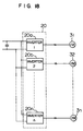
- An
inverter apparatus 20 comprises a plurality of unit inverters 20a to 20n run so as to have running phases shifted by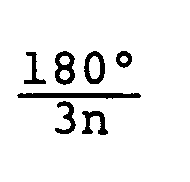
respectively. Their output voltages are summed up by amultiple transformer 30. The resultant voltage is supplied to a three-phase induction motor 3 to drive themotor 3. Although not especially illustrated, each unit inverter is associated with a circuit equivalent to the control circuit shown in Fig. 1. Sampling periods and their durations as shown in Fig. 17 stored beforehand into data tables 40a to 40n respectively associated with the unit inverters 20a to 20n. By doing so, the electromagnetic vibration tone generated from themotor 3 becomes a compound of frequencies nearly equivalent to sampling frequencies of the unit inverters. - In the present embodiment, the information tone generated as the electromagnetic vibration tone when an abnormal running state has been detected can be made more complex than that of the above described embodiments. If a combination of frequencies to be composed is made to agree with frequency components of voice, for example, the information tone can be changed to a voice message such as a message "overspeed has occurred in the motor" to inform of the abnormal running state more clearly.
- By combining this embodiment with the embodiment shown in Fig. 8, it becomes possible to generate a chord as the electromagnetic vibration tone, resulting in more comfortable music. In case a plurality of motors are run in parallel, a similar effect can be obtained by using configuration as shown in Fig. 18.
- If the present invention is applied to house hold appliances using a PWM inverter drive motor system, it is possible to use effectively the electromagnetic vibration tones as an alarm, a message or BGM (background music), resulting in favorable feeling of use without noises.
- Further, if the present embodiment is applied to a plant system using a PWM inverter drive motor system, it becomes possible to use effectively the electromagnetic vibration tones especially as an alarm when abnormality occurs in the system.
Claims (6)
- A control apparatus for controlling at least one PWM inverter (2), which receives an AC power and generates an AC output having a controlled frequency to be supplied to at least one AC motor (3) to drive said at least one motor by a current if and at a speed ωf, said control apparatus comprising:
control means (7) including command value generating means (9) for generating a command value for an output frequency of the inverter (2) based on a motor speed command ω* externally applied thereto and PWM signal generating means (8) for sampling the command value periodically at a given sampling frequency and generating, on the basis of the sampled command value, a PWM signal for controlling the inverter;
characterized in that
an abnormal state detecting section (12) monitors the detected current value if and the detected speed value ωf by comparing them with their limit values iLIM and ωLIM respectively set;
under a normal running state, with respective detected values less than said limit values, the abnormal state detecting section (12) outputs a constant sampling period Ts; and
when the detected values of current if and of speed ωf exceed said current limit value iLIM or said speed limit value ωLIM the succeeding sampling period Ts is changed according to prestored values of sampling periods and their durations L in a table (11) whereby said AC motor (3) generates electromagnetic vibration tones corresponding to these sampling periods Tsn. - A control apparatus according to claim 1,
wherein said control means (7) comprises means (702) for detecting a ripple frequency fr of said motor current if and means (701) for controlling the motor current if such that the detected ripple frequency becomes a selected value fr*. - A control apparatus according to claim 1,
wherein said control means (7) comprises means for detecting the amplitude of the ripple current of said motor current if and means (701) for controlling the change width of said detected ripple current amplitude to be within a selected range. - A control apparatus according to one of the claim 2 to 3,
wherein said sampling frequency is so controlled as to become lower as power of the electromagnetic vibration tone of said motor is increased. - A control apparatus according to claim 2,
wherein in said table (11) are stored beforehand change patterns of the sampling period and its duration and wherein said sampling periods are controlled in accordance with said stored patterns so that the electromagnetic vibration tone has a rhythm representing a running state of the AC motor (3). - A control apparatus according to claim 1,
characterized in that the PWM inverter includes a plurality of PWM inverter units (20a, 20b, ...20n), each receiving the AC power and generating an AC output having a controlled frequency so that the AC motor is dirven by a combination of the outputs of the PWM inverter units,
that the command value generating means (9), the PWM signal generating means (8) and the sampling frequency controlling means (10) are provided to each of the PWM inverter units, and
that the sampling frequency in the PWM signal generating means is controlled in each of the PWM inverter units so that the AC motor generates a preselected electromagnetic tone when the AC motor is driven by the combination of the outputs of the PWM inverter units.
Applications Claiming Priority (2)
| Application Number | Priority Date | Filing Date | Title |
|---|---|---|---|
| JP23361988 | 1988-09-20 | ||
| JP233619/88 | 1988-09-20 |
Publications (3)
| Publication Number | Publication Date |
|---|---|
| EP0360210A2 EP0360210A2 (en) | 1990-03-28 |
| EP0360210A3 EP0360210A3 (en) | 1990-11-28 |
| EP0360210B1 true EP0360210B1 (en) | 1994-06-22 |
Family
ID=16957885
Family Applications (1)
| Application Number | Title | Priority Date | Filing Date |
|---|---|---|---|
| EP89117283A Expired - Lifetime EP0360210B1 (en) | 1988-09-20 | 1989-09-19 | Control apparatus and method for controlling an inverter for driving AC motor |
Country Status (3)
| Country | Link |
|---|---|
| US (1) | US4965504A (en) |
| EP (1) | EP0360210B1 (en) |
| DE (1) | DE68916350T2 (en) |
Families Citing this family (27)
| Publication number | Priority date | Publication date | Assignee | Title |
|---|---|---|---|---|
| DE3912706A1 (en) * | 1989-04-18 | 1990-10-25 | Siemens Ag | METHOD FOR QUIET OPERATION OF A MACHINE FEEDED BY A PULSE INVERTER |
| JPH0378490A (en) * | 1989-08-18 | 1991-04-03 | Fujitsu Ltd | Pwm controlling type of spindle motor |
| US5418932A (en) * | 1990-02-01 | 1995-05-23 | Hitachi, Ltd. | Generation of width modulated pulses by relatively adjusting rising and falling edges upon comparison of counter with programmably stored values |
| US5483167A (en) * | 1992-09-08 | 1996-01-09 | Mitsubishi Denki Kabushiki Kaisha | Computer controlled ground detecting method for inverter unit and apparatus therefor |
| JP2846203B2 (en) * | 1992-12-09 | 1999-01-13 | 三菱電機株式会社 | Parallel multiple inverter device |
| US5473497A (en) * | 1993-02-05 | 1995-12-05 | Franklin Electric Co., Inc. | Electronic motor load sensing device |
| IT1266377B1 (en) * | 1993-05-31 | 1996-12-27 | Merloni Antonio Spa | POWER SUPPLY OF INDUCTION ELECTRIC MOTORS BY MEANS OF ELECTRONIC INVERTERS |
| US5625545A (en) * | 1994-03-01 | 1997-04-29 | Halmar Robicon Group | Medium voltage PWM drive and method |
| US5528446A (en) * | 1994-07-05 | 1996-06-18 | Ford Motor Company | Integrated power module diagnostic unit |
| JP3091388B2 (en) * | 1995-04-19 | 2000-09-25 | ファナック株式会社 | Motor runaway detection method and runaway detection device |
| JPH0923501A (en) * | 1995-07-03 | 1997-01-21 | Hitachi Ltd | Electric car control device |
| US5656912A (en) * | 1995-09-29 | 1997-08-12 | A. O. Smith Corporation | Method and apparatus for controlling a motor |
| JPH1023756A (en) * | 1996-06-28 | 1998-01-23 | Mitsubishi Electric Corp | Voltage source inverter device and control method thereof |
| US6226324B1 (en) | 1997-12-17 | 2001-05-01 | The Foxboro Company | Methods and systems for trimming a PWM signal |
| KR100318228B1 (en) * | 1998-07-30 | 2002-04-22 | 윤종용 | Compressor Control Method of Refrigerator |
| DE19938670A1 (en) * | 1999-08-14 | 2001-05-17 | Braun Gmbh | Electric electric motor controlled as an electro-acoustic converter |
| US6239991B1 (en) * | 2000-08-21 | 2001-05-29 | Nidec America Corporation | Control circuit compensating for malfunction of pulse width modulation circuitry |
| JP3978348B2 (en) * | 2002-02-14 | 2007-09-19 | 株式会社日立エルジーデータストレージ | Optical disc apparatus and optical pickup movement control method |
| JP2008099412A (en) * | 2006-10-11 | 2008-04-24 | Futaba Corp | Motor control device |
| JP4833812B2 (en) * | 2006-11-30 | 2011-12-07 | パナソニック株式会社 | PWM drive device and output offset correction method thereof |
| JP2008295161A (en) * | 2007-05-23 | 2008-12-04 | Daikin Ind Ltd | Power converter |
| EP2319724B1 (en) * | 2008-08-28 | 2021-03-03 | Nissan Motor Co., Ltd. | Vehicle operation sound control apparatus and control method |
| JP4877397B2 (en) * | 2010-01-22 | 2012-02-15 | 株式会社デンソー | Current sensor abnormality diagnosis device and sensor abnormality diagnosis device |
| US20140043870A1 (en) * | 2012-08-07 | 2014-02-13 | Yaskawa America, Inc. | Three phase boost converter to achieve unity power factor and low input current harmonics for use with ac to dc rectifiers |
| US9914228B1 (en) * | 2016-08-31 | 2018-03-13 | Michael Matthews | Smart clipper |
| FR3072227B1 (en) * | 2017-10-06 | 2019-10-18 | Foundation Brakes France Sas | ELECTRIC MOTOR SOUND TRANSMITTER |
| CN113691173A (en) * | 2021-07-23 | 2021-11-23 | 江苏东成工具科技有限公司 | Current control method |
Family Cites Families (6)
| Publication number | Priority date | Publication date | Assignee | Title |
|---|---|---|---|---|
| JPS5944975A (en) * | 1982-09-03 | 1984-03-13 | Hitachi Ltd | Controlling method and device for pwm inverter |
| US4470092A (en) * | 1982-09-27 | 1984-09-04 | Allen-Bradley Company | Programmable motor protector |
| JPS59122392A (en) * | 1982-12-27 | 1984-07-14 | Hitachi Ltd | Induction motor control device |
| US4467260A (en) * | 1983-04-20 | 1984-08-21 | Westinghouse Electric Corp. | Motor control apparatus with rotor heating protection |
| US4680526A (en) * | 1984-08-21 | 1987-07-14 | Hitachi, Ltd. | Method of controlling inverter-driven induction motor |
| JPH07118956B2 (en) * | 1987-02-17 | 1995-12-18 | 株式会社明電舎 | Vector controller |
-
1989
- 1989-09-13 US US07/406,516 patent/US4965504A/en not_active Expired - Fee Related
- 1989-09-19 EP EP89117283A patent/EP0360210B1/en not_active Expired - Lifetime
- 1989-09-19 DE DE68916350T patent/DE68916350T2/en not_active Expired - Fee Related
Also Published As
| Publication number | Publication date |
|---|---|
| DE68916350T2 (en) | 1994-12-08 |
| US4965504A (en) | 1990-10-23 |
| EP0360210A3 (en) | 1990-11-28 |
| EP0360210A2 (en) | 1990-03-28 |
| DE68916350D1 (en) | 1994-07-28 |
Similar Documents
| Publication | Publication Date | Title |
|---|---|---|
| US4965504A (en) | Control apparatus for inverter for driving AC motor | |
| US5706186A (en) | Hybrid pulse width modulation method and apparatus | |
| US4656572A (en) | PWM inverter | |
| US6922037B2 (en) | Rotating induction apparatus | |
| US5872435A (en) | Electrical drive arrangement | |
| JP2000505638A (en) | Direct torque control inverter device | |
| EP0078698B1 (en) | Ac motor control method and arrangement | |
| US5422557A (en) | Method and apparatus for controlling the speed of a single phase induction motor using frequency variation | |
| US4565955A (en) | Synchronous motor device for timepiece | |
| JPS5915478B2 (en) | Method and device for driving an alternating current motor | |
| CA2159781A1 (en) | Apparatus for Starting a Switched Reluctance Motor | |
| JPH0789753B2 (en) | Control device for AC motor drive inverter | |
| HK10792A (en) | Apparatus for controlling a three-phase inverter supplying the a.c. motor of a lift | |
| EP0713285A2 (en) | Three-phase PWM signal generating device for inverters | |
| CA2129322A1 (en) | Stator Flux Oriented Control | |
| EP0600635A2 (en) | Parallel-connection multiple inverter system and control method therefor | |
| JPH04200294A (en) | Inverter device | |
| JPH0314000Y2 (en) | ||
| CA1296384C (en) | Frequency converter and a method of applying same | |
| JPH05344740A (en) | Inverter device | |
| GB2171266A (en) | PWM inverter | |
| SU1302416A1 (en) | Frequency regulator of d.c.voltage-to-a.c.voltage electric machine converter | |
| JP2852083B2 (en) | Inverter PWM control method and PWM inverter | |
| JPH01218363A (en) | Inverter controller | |
| JPH0720374B2 (en) | Inverter control device |
Legal Events
| Date | Code | Title | Description |
|---|---|---|---|
| PUAI | Public reference made under article 153(3) epc to a published international application that has entered the european phase |
Free format text: ORIGINAL CODE: 0009012 |
|
| AK | Designated contracting states |
Kind code of ref document: A2 Designated state(s): DE FR GB NL SE |
|
| PUAL | Search report despatched |
Free format text: ORIGINAL CODE: 0009013 |
|
| AK | Designated contracting states |
Kind code of ref document: A3 Designated state(s): DE FR GB NL SE |
|
| 17P | Request for examination filed |
Effective date: 19901106 |
|
| 17Q | First examination report despatched |
Effective date: 19921228 |
|
| GRAA | (expected) grant |
Free format text: ORIGINAL CODE: 0009210 |
|
| RBV | Designated contracting states (corrected) |
Designated state(s): DE FR NL SE |
|
| AK | Designated contracting states |
Kind code of ref document: B1 Designated state(s): DE FR NL SE |
|
| REF | Corresponds to: |
Ref document number: 68916350 Country of ref document: DE Date of ref document: 19940728 |
|
| ET | Fr: translation filed | ||
| EAL | Se: european patent in force in sweden |
Ref document number: 89117283.5 |
|
| PLBE | No opposition filed within time limit |
Free format text: ORIGINAL CODE: 0009261 |
|
| STAA | Information on the status of an ep patent application or granted ep patent |
Free format text: STATUS: NO OPPOSITION FILED WITHIN TIME LIMIT |
|
| 26N | No opposition filed | ||
| PGFP | Annual fee paid to national office [announced via postgrant information from national office to epo] |
Ref country code: FR Payment date: 19950718 Year of fee payment: 7 |
|
| PGFP | Annual fee paid to national office [announced via postgrant information from national office to epo] |
Ref country code: SE Payment date: 19950724 Year of fee payment: 7 |
|
| PGFP | Annual fee paid to national office [announced via postgrant information from national office to epo] |
Ref country code: NL Payment date: 19950929 Year of fee payment: 7 |
|
| PGFP | Annual fee paid to national office [announced via postgrant information from national office to epo] |
Ref country code: DE Payment date: 19951130 Year of fee payment: 7 |
|
| PG25 | Lapsed in a contracting state [announced via postgrant information from national office to epo] |
Ref country code: SE Effective date: 19960920 |
|
| PG25 | Lapsed in a contracting state [announced via postgrant information from national office to epo] |
Ref country code: FR Effective date: 19960930 |
|
| PG25 | Lapsed in a contracting state [announced via postgrant information from national office to epo] |
Ref country code: NL Effective date: 19970401 |
|
| NLV4 | Nl: lapsed or anulled due to non-payment of the annual fee |
Effective date: 19970401 |
|
| PG25 | Lapsed in a contracting state [announced via postgrant information from national office to epo] |
Ref country code: DE Effective date: 19970603 |
|
| EUG | Se: european patent has lapsed |
Ref document number: 89117283.5 |
|
| REG | Reference to a national code |
Ref country code: FR Ref legal event code: ST |
|
| REG | Reference to a national code |
Ref country code: FR Ref legal event code: ST |