EP0360204B1 - Unit apt to act upon the flow - Google Patents
Unit apt to act upon the flow Download PDFInfo
- Publication number
- EP0360204B1 EP0360204B1 EP89117270A EP89117270A EP0360204B1 EP 0360204 B1 EP0360204 B1 EP 0360204B1 EP 89117270 A EP89117270 A EP 89117270A EP 89117270 A EP89117270 A EP 89117270A EP 0360204 B1 EP0360204 B1 EP 0360204B1
- Authority
- EP
- European Patent Office
- Prior art keywords
- actuator
- flow path
- flow
- unit
- stator
- Prior art date
- Legal status (The legal status is an assumption and is not a legal conclusion. Google has not performed a legal analysis and makes no representation as to the accuracy of the status listed.)
- Expired - Lifetime
Links
- 238000004804 winding Methods 0.000 claims description 15
- 230000005672 electromagnetic field Effects 0.000 claims description 4
- 238000012856 packing Methods 0.000 abstract description 15
- 239000007788 liquid Substances 0.000 abstract description 10
- 235000013336 milk Nutrition 0.000 abstract description 5
- 239000008267 milk Substances 0.000 abstract description 5
- 210000004080 milk Anatomy 0.000 abstract description 5
- 238000005406 washing Methods 0.000 description 7
- 239000012530 fluid Substances 0.000 description 6
- 238000000034 method Methods 0.000 description 4
- HEMHJVSKTPXQMS-UHFFFAOYSA-M Sodium hydroxide Chemical compound [OH-].[Na+] HEMHJVSKTPXQMS-UHFFFAOYSA-M 0.000 description 3
- 238000004140 cleaning Methods 0.000 description 3
- 230000008569 process Effects 0.000 description 3
- 238000010276 construction Methods 0.000 description 2
- 238000005429 filling process Methods 0.000 description 2
- 235000011389 fruit/vegetable juice Nutrition 0.000 description 2
- 238000010438 heat treatment Methods 0.000 description 2
- 230000036512 infertility Effects 0.000 description 2
- 235000021262 sour milk Nutrition 0.000 description 2
- 230000001954 sterilising effect Effects 0.000 description 2
- 239000000126 substance Substances 0.000 description 2
- 230000009471 action Effects 0.000 description 1
- 230000004888 barrier function Effects 0.000 description 1
- 239000012459 cleaning agent Substances 0.000 description 1
- 230000003670 easy-to-clean Effects 0.000 description 1
- 230000001939 inductive effect Effects 0.000 description 1
- 238000004519 manufacturing process Methods 0.000 description 1
- 239000000463 material Substances 0.000 description 1
- 230000002906 microbiologic effect Effects 0.000 description 1
- 230000009467 reduction Effects 0.000 description 1
- 235000011121 sodium hydroxide Nutrition 0.000 description 1
- 239000007787 solid Substances 0.000 description 1
- 238000004659 sterilization and disinfection Methods 0.000 description 1
- 239000003206 sterilizing agent Substances 0.000 description 1
Images
Classifications
-
- F—MECHANICAL ENGINEERING; LIGHTING; HEATING; WEAPONS; BLASTING
- F16—ENGINEERING ELEMENTS AND UNITS; GENERAL MEASURES FOR PRODUCING AND MAINTAINING EFFECTIVE FUNCTIONING OF MACHINES OR INSTALLATIONS; THERMAL INSULATION IN GENERAL
- F16K—VALVES; TAPS; COCKS; ACTUATING-FLOATS; DEVICES FOR VENTING OR AERATING
- F16K31/00—Actuating devices; Operating means; Releasing devices
- F16K31/02—Actuating devices; Operating means; Releasing devices electric; magnetic
- F16K31/06—Actuating devices; Operating means; Releasing devices electric; magnetic using a magnet, e.g. diaphragm valves, cutting off by means of a liquid
- F16K31/0644—One-way valve
- F16K31/0655—Lift valves
-
- B—PERFORMING OPERATIONS; TRANSPORTING
- B08—CLEANING
- B08B—CLEANING IN GENERAL; PREVENTION OF FOULING IN GENERAL
- B08B9/00—Cleaning hollow articles by methods or apparatus specially adapted thereto
-
- B—PERFORMING OPERATIONS; TRANSPORTING
- B67—OPENING, CLOSING OR CLEANING BOTTLES, JARS OR SIMILAR CONTAINERS; LIQUID HANDLING
- B67C—CLEANING, FILLING WITH LIQUIDS OR SEMILIQUIDS, OR EMPTYING, OF BOTTLES, JARS, CANS, CASKS, BARRELS, OR SIMILAR CONTAINERS, NOT OTHERWISE PROVIDED FOR; FUNNELS
- B67C3/00—Bottling liquids or semiliquids; Filling jars or cans with liquids or semiliquids using bottling or like apparatus; Filling casks or barrels with liquids or semiliquids
- B67C3/02—Bottling liquids or semiliquids; Filling jars or cans with liquids or semiliquids using bottling or like apparatus
- B67C3/22—Details
- B67C3/28—Flow-control devices, e.g. using valves
-
- F—MECHANICAL ENGINEERING; LIGHTING; HEATING; WEAPONS; BLASTING
- F04—POSITIVE - DISPLACEMENT MACHINES FOR LIQUIDS; PUMPS FOR LIQUIDS OR ELASTIC FLUIDS
- F04B—POSITIVE-DISPLACEMENT MACHINES FOR LIQUIDS; PUMPS
- F04B17/00—Pumps characterised by combination with, or adaptation to, specific driving engines or motors
- F04B17/03—Pumps characterised by combination with, or adaptation to, specific driving engines or motors driven by electric motors
- F04B17/04—Pumps characterised by combination with, or adaptation to, specific driving engines or motors driven by electric motors using solenoids
- F04B17/046—Pumps characterised by combination with, or adaptation to, specific driving engines or motors driven by electric motors using solenoids the fluid flowing through the moving part of the motor
-
- F—MECHANICAL ENGINEERING; LIGHTING; HEATING; WEAPONS; BLASTING
- F16—ENGINEERING ELEMENTS AND UNITS; GENERAL MEASURES FOR PRODUCING AND MAINTAINING EFFECTIVE FUNCTIONING OF MACHINES OR INSTALLATIONS; THERMAL INSULATION IN GENERAL
- F16K—VALVES; TAPS; COCKS; ACTUATING-FLOATS; DEVICES FOR VENTING OR AERATING
- F16K31/00—Actuating devices; Operating means; Releasing devices
- F16K31/02—Actuating devices; Operating means; Releasing devices electric; magnetic
- F16K31/06—Actuating devices; Operating means; Releasing devices electric; magnetic using a magnet, e.g. diaphragm valves, cutting off by means of a liquid
- F16K31/0644—One-way valve
- F16K31/0651—One-way valve the fluid passing through the solenoid coil
-
- Y—GENERAL TAGGING OF NEW TECHNOLOGICAL DEVELOPMENTS; GENERAL TAGGING OF CROSS-SECTIONAL TECHNOLOGIES SPANNING OVER SEVERAL SECTIONS OF THE IPC; TECHNICAL SUBJECTS COVERED BY FORMER USPC CROSS-REFERENCE ART COLLECTIONS [XRACs] AND DIGESTS
- Y10—TECHNICAL SUBJECTS COVERED BY FORMER USPC
- Y10T—TECHNICAL SUBJECTS COVERED BY FORMER US CLASSIFICATION
- Y10T137/00—Fluid handling
- Y10T137/7722—Line condition change responsive valves
- Y10T137/7758—Pilot or servo controlled
- Y10T137/7759—Responsive to change in rate of fluid flow
-
- Y—GENERAL TAGGING OF NEW TECHNOLOGICAL DEVELOPMENTS; GENERAL TAGGING OF CROSS-SECTIONAL TECHNOLOGIES SPANNING OVER SEVERAL SECTIONS OF THE IPC; TECHNICAL SUBJECTS COVERED BY FORMER USPC CROSS-REFERENCE ART COLLECTIONS [XRACs] AND DIGESTS
- Y10—TECHNICAL SUBJECTS COVERED BY FORMER USPC
- Y10T—TECHNICAL SUBJECTS COVERED BY FORMER US CLASSIFICATION
- Y10T137/00—Fluid handling
- Y10T137/7722—Line condition change responsive valves
- Y10T137/7758—Pilot or servo controlled
- Y10T137/7761—Electrically actuated valve
Definitions
- the present invention relates to a unit apt to act upon the flow comprising a driving means with a stator and an actuator connected to a device situated in the flow path which acts upon the flow.
- devices acting upon the flow are used for the control of the flow rate.
- devices acting upon, or controlling, the flow may be mentioned various types of pumps, but also valves, throttles and similar devices, above all for the reduction of the flow rate.
- the intermediate flow path thus not only has to be immaculate from a point of view of hygiene, that is to say it should be simple to wash and to sterilize, but it also has to be completely sealed off (also from a microbiological aspect) towards the non-sterile environment. It is an aim, therefore, that the flow path should not contain any manoevring devices such as movable axles or the like which extend into the flow path from the non-sterile outside.
- a unit as described in the preamble of claim 1 is known by DE-A 1 550 413.
- the valve of this unit is controlled by electromagnetic forces according to which a shaft on which the valve member is attached can be moved in a longitudinal direction with regard to the axis of the flow path.
- the actuator and the shaft are rotatable around the axis extending in longitudinal direction of the flow path.
- the shaft is movable not only in the axial direction but can also rotated which allows more options for controlling the flow.
- the unit in accordance with the invention with the actuator situated in the flow path and mechanically separated from the stator ( “mechanically separated” here means that the actuator cannot be acted upon by mechanical means such as levers, shafts etc. from the stator, but is separated from the same by means of an uninterrupted, liquid and microbiologically tight barrier) it is made possible completely to avoid movable seals in contact with the contents.
- the unit nevertheless will be drivable and controllable from the outside and will obtain a simple and purposeful design which, moreover, permits washing and sterilizing by known methods, e.g. hot steam, or chemicals.
- the arrangement will be simple and not highly cost-demanding at the same time as obtaining a sturdy construction which is suitable for handling of the most varied types of fluids.
- the unit may be used optionally for different mechanical applications such as a pump or a valve arrangement.
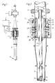
- Fig. 1 shows partly in section a unit for flow control in accordance with the invention.
- Fig. 2 shows on a larger scale a part of the unit in accordance with Fig. 1 in cross-section.
- the unit in accordance with the invention is shown in its preferred embodiment as it can be designed for use in a packing machine of known type which portions out defined amounts of contents, e.g. milk, sour milk or juice, into preformed packing containers.
- contents e.g. milk, sour milk or juice
- the unit in accordance with the invention comprises a magnetically inductive flow meter 4, which is of a known type and generates a control signal which is passed to a control equipment 5.
- control equipment which compares the flow signal with a predetermined set-point curve, a control signal is generated to a driving means 6 for the valve 3 so that the flow through the filling pipe 2 is controlled to agreement with a predetermined value.
- control equipment 5 gives a signal to the driving means 6 to urge the valve 3 towards the closed position which makes possible to fill with good accuracy each individual packing container with the desired amount of contents.
- the driving means 6 comprises a stator 7 firmly mounted around the upper end of the filling pipe and an actuator 8 placed inside the same in the flow path which is connected via a shaft 9 to the flow-controlling device or the valve 3 at the bottom end of the filling pipe 2.
- the shaft 9 is supported at its upper end in a bearing 10 which is held up by the bearing disc 11 firmly connected to the feed line 1.
- the bearing disc 11 is provided with flow passes 12 through which the pumped liquid fluid or the contents can pass.
- the shaft 9 is connected at its bottom end to a valve member 13 which comprises a number of flow passages 14.
- the valve member 13 rests with its bottom end against a valve seat 15 which has openings 16 corresponding to the openings 14.
- the valve member 13 is rotatable so as to bring the openings 14,16 straight before one another, or, in closed position of the valve 3, bring the openings 14 straight before a number of solid parts of the valve seat situated between the openings 16.
- the shaft 9 can perform a rotational movement as well as an axial movement. The latter means that the valve member 13 is lifted off the valve seat 15, which e.g. facilitates washing and cleaning of the valve, as will be explained in greater detail in the following.
- the driving means 6, as mentioned earlier, comprises the stationary stator 7 which is situated outside the flow path and is liquid-tight and microbiologically separated from the same with the help of the cylindrical wall of the feed line 1, and the actuator 8 which is situated in the flow path.
- the driving means more particularly, is located in a widened part of the flow path which forms a chamber 17 whose inside diameter is only a few per cent greater than the outer diameter of the actuator 8.
- a passage 18 exists between the likewise cylindrical internal wall surface of the actuator 8 and the shaft 9.
- the flow area in this passage 18 corresponds substantially to the free flow area in the filling pipe 2.
- the actuator 8 is connected rigidly to the shaft 9 via a number of fixed arms 19 at the upper and lower end of the actuator.
- stator 7 as well as the actuator 8, as mentioned earlier, are substantially cylindrical or annular and situated concentrically in relation to one another, and the actuator 8 is adapted to rotate the shaft 9 or be displaced in axial direction of the shaft 9 through action by means of the magnetic field of forces generated by the stator.
- stator 7 comprises an operating winding 20 around a stator core 21, this winding being adapted so as to be connected via the control equipment 5 and an electrical connecting line 22 to a source of current (no shown). Through this an electromagnetic field of forces is generated which influences an actuator magnet 23 so that the actuator 8 is rotated around the shaft 9.
- the actuator magnet 23 is displaced slightly in upwards direction in relation to the stator core of the operating winding 20 which means that the field of forces generated not only acts upon the actuator magnet 23 in rotational direction, but also seeks to urge the same to assume a position at a level with the stator core 21, which thus creates a downwards directed force which via the shaft 9 is transferred to the valve member 13 and causes thesame to rest against the valve seat 15.
- the stator 7 Beside the operating winding 20 the stator 7 comprises a solenoid winding 24 and a solenoid core 25 which are situated at some distance above the operating winding 20.
- the actuator 8 has corresponding secondary poles 26 which are slightly displaced downwards in relation to the solenoid core 25.
- a magnetic field of force will act upon the secondary poles 26 so that these together with the actuator 8 and the shaft 9 are lifted slightly upwards in axial direction. This influences vis the bottom end of the shaft 9 the valve member 13 so that the same is lifted slightly from its contact against the valve seat 15.
- the driving means 6 comprises beside the two windings 20, 24 also a position indicator 28 which consists of two parts, namely a stator part 29 and an actuator part 30 surrounded by the same.
- the position indicator 28, which may be an angular position measuring system of conventional type, provides the control equipment 5 via the line 31 with a signal which gives information on the present rotational position of the actuator 8 in relation to the stator 7 thus providing a measure of the degree of opening of the valve 3 and being able to be used in combination with the signal from the flow meter 4 for controlling the current feed to the operating winding 20 so that the desired volume of flow per unit of time is obtained.
- the valve 3 When production actually commences the valve 3 is opened in the first place owing to the control equipment 5 connecting the operating winding 20 to a source of current (not shown) so that a field of forces is created which acts upon the actuator magnet 23 so as to rotate via the fixed arms 19 the shaft 9, and with it the valve member 13, to the open position.
- the opening possibly may be done according to a predetermined opening curve which, as mentioned earlier, is programmed into the control equipment 5.
- the control equipment 5 is continuously informed regarding the present rotational position of the actuator 8 with the help of the position indicator 28, whose information concerning the angular position of the actuator 8 in relation to the stator 7 is fed continuously to the control equipment 5 via the line 31.
- valve member 13 As soon as the valve member 13 has been rotated to such a position that its flow passages 14 commence to overlap the flow passages 16 of the valve seat 15 the contents can flow out through the valve 3, and the flow of contents through the filling pipe 2, the feed line 1 and the flow meter is started. With the help of the flow meter 4 the control equipment 5 is informed continuously regarding the actual flow, and the opening area of the valve 3 is controlled by means of the control equipment 5 so that the required volume of contents is able to pass during the available time.
- the control equipment 5 acts upon the operating winding 20 via the line 22 so that the actuator magnet 23 rotates the actuator 8 to a position wherein the valve body 13 with the help of the shaft 9 is returned to its closed position.
- the closing of the valve 3 too may possibly be done according to a predetermined curve, the control equipment 5 being informed continuously of the angular position of the actuator 8 by means of the position indicator 28, as in the opening process.
- the filling process does not have to be controlled by a flow meter, but may also be coupled to some other measuring device, e.g. a level indicator or be time-controlled.
- the design of the unit in accordance with the invention with an actuator located in the flow path which is acted upon and is driven from the outside with the help of an electromagnetic field of forces makes it possible to maintain the flow path wholly separated from the environment, since any mechanical connection between the actuator part located in the flow path and means located outside the flow path is not necessary.
- the wall of the chamber 17 can be made smooth and wholly without bushings for movable axles or other manoeuvring means, thus making it possible to meet the very high demands which are made on the handling of liquid foodstuffs and especially on the handling of such liquid foodstuffs which have been previously sterilized, e.g. through heat treatment.
- the design of the actuator with a large central flow passage 18 means that the contents can pass easily, and the absence of contact surfaces between movable and fixed parts (apart from the bearing 10) renders the arrangement very easy to clean and to sterilize. To this contributes, of course, also the simple design of the construction and the fact that the parts present in the flow path can be made of non-corroding material which, moreover, is resistant to normally used washing and cleaning agents such as steam and caustic soda.
- the actuator 8 together with the shaft 9 and the valve member 13 can be raised to an upper position or possibly oscillate between an upper and a lower position during the course of the washing.
- This can be achieved in that the solenoid winding 24 via the line 27 and the control equipment 5 is connected to an electric source of current (not shown) so that an electromagnetic field of force is generated which acts upon the secondary poles 26 displaced in a direction axially downwards towards the valve 3, so that they are lifted and centred in relation to the solenoid core 25.
- the valve member 13 too is lifted off its contact with the valve seat 15 so that a passage is formed through which can pass the cleaning liquid or sterilizing medium.
- the movement of the actuator 8, on the one hand rotational and on the other hand upwards and downwards during the washing process facilitates the cleaning, not only in the space between the valve member 13 and the valve seat 15 but also in the space between the outer cylindrical surface of the actuator 8 and the interior wall of the chamber 17.
- the unit in accordance with the invention may be used also for the control of other types of devices acting upon the flow, e.g. other valve types, pumps or the like.
- the unit thus may be combined with valves of other types, e.g. axially movable valves, with the function of the windings 20, 24 being changed round so that the normal operating movement is axial whilst a rotary or twisting movement may be used in connection with the washing process.
- the shaft 9 appreciably shorter or possibly eliminate it if the actuator 8 itself is designed as a valve body.
- the actuator 8 may also be designed as a pump rotor or a pump piston with rotary motion or axial motion respectively.
Landscapes
- Engineering & Computer Science (AREA)
- General Engineering & Computer Science (AREA)
- Mechanical Engineering (AREA)
- Physics & Mathematics (AREA)
- Fluid Mechanics (AREA)
- Magnetically Actuated Valves (AREA)
- Filling Of Jars Or Cans And Processes For Cleaning And Sealing Jars (AREA)
- Basic Packing Technique (AREA)
- Dairy Products (AREA)
- Food Preservation Except Freezing, Refrigeration, And Drying (AREA)
- Flow Control (AREA)
- Structures Of Non-Positive Displacement Pumps (AREA)
- Non-Alcoholic Beverages (AREA)
- Reciprocating Pumps (AREA)
- Prostheses (AREA)
- Telephonic Communication Services (AREA)
- Tires In General (AREA)
- Pharmaceuticals Containing Other Organic And Inorganic Compounds (AREA)
Abstract
Description
- The present invention relates to a unit apt to act upon the flow comprising a driving means with a stator and an actuator connected to a device situated in the flow path which acts upon the flow.
- In the transport of fluids, especially liquids of different degrees of viscosity, devices acting upon the flow are used for the control of the flow rate. As examples of devices acting upon, or controlling, the flow may be mentioned various types of pumps, but also valves, throttles and similar devices, above all for the reduction of the flow rate.
- In the handling of certain types of fluids, e.g. liquid foodstuffs such as milk, sour milk, juice or the like very high demands are made on hygiene, so that the devices which are used e.g. for controlling the flow rate in these media must be designed so that they do not possess any complicatedly formed passages, pockets or other spaces which are difficult to clean. This is even more important in those cases where the fluid consists of a liquid sterilized beforehand, e.g. milk sterilized through heat treatment. This is often the case e.g. in packing machines where sterile milk is conducted continuously or in batches down into presterilized packing containers which are closed so as to be liquid-tight and microbiologically under sterile conditions. An uninterrupted sterility has to be ensured right from the sterilizer, where the fluid is sterilized, and up to the packing machine wherein the packing container filled with sterile contents is closed. The intermediate flow path thus not only has to be immaculate from a point of view of hygiene, that is to say it should be simple to wash and to sterilize, but it also has to be completely sealed off (also from a microbiological aspect) towards the non-sterile environment. It is an aim, therefore, that the flow path should not contain any manoevring devices such as movable axles or the like which extend into the flow path from the non-sterile outside. This is an aim, though, which until now has been difficult to achieve, since means acting upon the flow in the shape of pumps or valves necessary in the flow path had to be manoeuvred and controlled from the outside. Even though in practice it ought to be possible e.g. to build an enclosed, electric pump motor into a flow path, the movable part of the motor has to be sealed from the motor by means of a movable seal which, on the one hand, causes problems in connection with sterilization (thermal or chemical) of the device and, on the other hand, creates risks of a connection between the non-sterile interior of the motor and the flow path with non-sterility as a consequence.
- A unit as described in the preamble of
claim 1 is known by DE-A 1 550 413. The valve of this unit is controlled by electromagnetic forces according to which a shaft on which the valve member is attached can be moved in a longitudinal direction with regard to the axis of the flow path. - It is an object of the present invention to amend such unit in such way that further functions can be realized by simple means.
- The invention is claimed in claim 1: According to the invention the actuator and the shaft are rotatable around the axis extending in longitudinal direction of the flow path.
- That means that the shaft is movable not only in the axial direction but can also rotated which allows more options for controlling the flow.
- Further embodiments of the invention are claimed in subclaims.
- By designing the unit in accordance with the invention with the actuator situated in the flow path and mechanically separated from the stator ( "mechanically separated" here means that the actuator cannot be acted upon by mechanical means such as levers, shafts etc. from the stator, but is separated from the same by means of an uninterrupted, liquid and microbiologically tight barrier) it is made possible completely to avoid movable seals in contact with the contents. The unit, nevertheless will be drivable and controllable from the outside and will obtain a simple and purposeful design which, moreover, permits washing and sterilizing by known methods, e.g. hot steam, or chemicals. The arrangement will be simple and not highly cost-demanding at the same time as obtaining a sturdy construction which is suitable for handling of the most varied types of fluids. Finally the unit may be used optionally for different mechanical applications such as a pump or a valve arrangement.
- A preferred embodiment of the unit in accordance with the invention will now be described in greater detail with special reference to the attached schematic drawings which only show the details indispensable for an understanding of the invention.
- Fig. 1 shows partly in section a unit for flow control in accordance with the invention.
- Fig. 2 shows on a larger scale a part of the unit in accordance with Fig. 1 in cross-section.
- The unit in accordance with the invention is shown in its preferred embodiment as it can be designed for use in a packing machine of known type which portions out defined amounts of contents, e.g. milk, sour milk or juice, into preformed packing containers. The contents are passed to the packing container via a
feed line 1, whose bottom end is designed as afilling pipe 2 with a device acting upon the flow in the form of a valve 3. The unit in accordance with the invention comprises a magnetically inductive flow meter 4, which is of a known type and generates a control signal which is passed to acontrol equipment 5. With the help of the control equipment, which compares the flow signal with a predetermined set-point curve, a control signal is generated to a driving means 6 for the valve 3 so that the flow through thefilling pipe 2 is controlled to agreement with a predetermined value. When the flow meter 4 indicates that the desired quantity of contents has passed, thecontrol equipment 5 gives a signal to the driving means 6 to urge the valve 3 towards the closed position which makes possible to fill with good accuracy each individual packing container with the desired amount of contents. - The driving means 6 comprises a
stator 7 firmly mounted around the upper end of the filling pipe and anactuator 8 placed inside the same in the flow path which is connected via a shaft 9 to the flow-controlling device or the valve 3 at the bottom end of thefilling pipe 2. The shaft 9 is supported at its upper end in abearing 10 which is held up by thebearing disc 11 firmly connected to thefeed line 1. Thebearing disc 11 is provided with flow passes 12 through which the pumped liquid fluid or the contents can pass. - The shaft 9 is connected at its bottom end to a
valve member 13 which comprises a number offlow passages 14. Thevalve member 13 rests with its bottom end against avalve seat 15 which hasopenings 16 corresponding to theopenings 14. Thevalve member 13 is rotatable so as to bring theopenings openings 14 straight before a number of solid parts of the valve seat situated between theopenings 16. The shaft 9 can perform a rotational movement as well as an axial movement. The latter means that thevalve member 13 is lifted off thevalve seat 15, which e.g. facilitates washing and cleaning of the valve, as will be explained in greater detail in the following. - The driving means 6, as mentioned earlier, comprises the
stationary stator 7 which is situated outside the flow path and is liquid-tight and microbiologically separated from the same with the help of the cylindrical wall of thefeed line 1, and theactuator 8 which is situated in the flow path. The driving means, more particularly, is located in a widened part of the flow path which forms achamber 17 whose inside diameter is only a few per cent greater than the outer diameter of theactuator 8. Beside the passage formed as a result between the outer surface of thecylindrical actuator 8 and the surrounding, cylindrical pipe wall, a passage 18 exists between the likewise cylindrical internal wall surface of theactuator 8 and the shaft 9. The flow area in this passage 18 corresponds substantially to the free flow area in thefilling pipe 2. Theactuator 8 is connected rigidly to the shaft 9 via a number of fixedarms 19 at the upper and lower end of the actuator. - The
stator 7 as well as theactuator 8, as mentioned earlier, are substantially cylindrical or annular and situated concentrically in relation to one another, and theactuator 8 is adapted to rotate the shaft 9 or be displaced in axial direction of the shaft 9 through action by means of the magnetic field of forces generated by the stator. To this end thestator 7 comprises an operating winding 20 around astator core 21, this winding being adapted so as to be connected via thecontrol equipment 5 and anelectrical connecting line 22 to a source of current (no shown). Through this an electromagnetic field of forces is generated which influences anactuator magnet 23 so that theactuator 8 is rotated around the shaft 9. Theactuator magnet 23 is displaced slightly in upwards direction in relation to the stator core of the operating winding 20 which means that the field of forces generated not only acts upon theactuator magnet 23 in rotational direction, but also seeks to urge the same to assume a position at a level with thestator core 21, which thus creates a downwards directed force which via the shaft 9 is transferred to thevalve member 13 and causes thesame to rest against thevalve seat 15. - Beside the operating winding 20 the
stator 7 comprises a solenoid winding 24 and asolenoid core 25 which are situated at some distance above the operating winding 20. Theactuator 8 has correspondingsecondary poles 26 which are slightly displaced downwards in relation to thesolenoid core 25. When the solenoid winding 24 via aline 27 is fed with current from the control equipment 5 a magnetic field of force will act upon thesecondary poles 26 so that these together with theactuator 8 and the shaft 9 are lifted slightly upwards in axial direction. This influences vis the bottom end of the shaft 9 thevalve member 13 so that the same is lifted slightly from its contact against thevalve seat 15. - The driving means 6 comprises beside the two
windings 20, 24 also aposition indicator 28 which consists of two parts, namely astator part 29 and an actuator part 30 surrounded by the same. Theposition indicator 28, which may be an angular position measuring system of conventional type, provides thecontrol equipment 5 via theline 31 with a signal which gives information on the present rotational position of theactuator 8 in relation to thestator 7 thus providing a measure of the degree of opening of the valve 3 and being able to be used in combination with the signal from the flow meter 4 for controlling the current feed to the operating winding 20 so that the desired volume of flow per unit of time is obtained. - When the unit in accordance with the invention is used in a packing machine of the conventional type for the proportioning out of liquid contents to packing containers placed at the bottom end of the filling pipe provided with a valve, first of all the set value which is to be applicable is transmitted to the
control equipment 5, that is to say information regarding the quantity of contents which is to pass the flow meter 4 on filling of a packing container with the required quantity of contents, and possibly also a predetermined curve for the opening and closing of the valve 3. On starting of the packing machine contents are introduced in the first place so that the feed line as well as thefilling pipe 2 will be wholly filled with contents. When production actually commences the valve 3 is opened in the first place owing to thecontrol equipment 5 connecting the operating winding 20 to a source of current (not shown) so that a field of forces is created which acts upon theactuator magnet 23 so as to rotate via thefixed arms 19 the shaft 9, and with it thevalve member 13, to the open position. In order to obtain a smooth opening process, the opening possibly may be done according to a predetermined opening curve which, as mentioned earlier, is programmed into thecontrol equipment 5. Thecontrol equipment 5 is continuously informed regarding the present rotational position of theactuator 8 with the help of theposition indicator 28, whose information concerning the angular position of theactuator 8 in relation to thestator 7 is fed continuously to thecontrol equipment 5 via theline 31. - As soon as the
valve member 13 has been rotated to such a position that itsflow passages 14 commence to overlap theflow passages 16 of thevalve seat 15 the contents can flow out through the valve 3, and the flow of contents through thefilling pipe 2, thefeed line 1 and the flow meter is started. With the help of the flow meter 4 thecontrol equipment 5 is informed continuously regarding the actual flow, and the opening area of the valve 3 is controlled by means of thecontrol equipment 5 so that the required volume of contents is able to pass during the available time. When the correct quantity of contents for the filling of a packing container to the required level has passed the flow meter 4, thecontrol equipment 5 acts upon the operating winding 20 via theline 22 so that theactuator magnet 23 rotates theactuator 8 to a position wherein thevalve body 13 with the help of the shaft 9 is returned to its closed position. The closing of the valve 3 too may possibly be done according to a predetermined curve, thecontrol equipment 5 being informed continuously of the angular position of theactuator 8 by means of theposition indicator 28, as in the opening process. When filling contents of an uncomplicated behaviour a purely reciprocating control may be chosen, whereas contents which are difficult to handle, e.g. contents which tend to froth during the filling process, are handled better by setting the control equipment so that the opening as well as the closing process take place according to a predetermined curve appropriate for the particular contents. The filling process does not have to be controlled by a flow meter, but may also be coupled to some other measuring device, e.g. a level indicator or be time-controlled. - The design of the unit in accordance with the invention with an actuator located in the flow path which is acted upon and is driven from the outside with the help of an electromagnetic field of forces makes it possible to maintain the flow path wholly separated from the environment, since any mechanical connection between the actuator part located in the flow path and means located outside the flow path is not necessary. As a result the wall of the
chamber 17 can be made smooth and wholly without bushings for movable axles or other manoeuvring means, thus making it possible to meet the very high demands which are made on the handling of liquid foodstuffs and especially on the handling of such liquid foodstuffs which have been previously sterilized, e.g. through heat treatment. The design of the actuator with a large central flow passage 18 means that the contents can pass easily, and the absence of contact surfaces between movable and fixed parts (apart from the bearing 10) renders the arrangement very easy to clean and to sterilize. To this contributes, of course, also the simple design of the construction and the fact that the parts present in the flow path can be made of non-corroding material which, moreover, is resistant to normally used washing and cleaning agents such as steam and caustic soda. - To facilitate the washing of the valve 3 as well as of the
actuator 8 and the inner wall surface of thechamber 17, theactuator 8 together with the shaft 9 and thevalve member 13 can be raised to an upper position or possibly oscillate between an upper and a lower position during the course of the washing. This can be achieved in that the solenoid winding 24 via theline 27 and thecontrol equipment 5 is connected to an electric source of current (not shown) so that an electromagnetic field of force is generated which acts upon thesecondary poles 26 displaced in a direction axially downwards towards the valve 3, so that they are lifted and centred in relation to thesolenoid core 25. Through this thevalve member 13 too is lifted off its contact with thevalve seat 15 so that a passage is formed through which can pass the cleaning liquid or sterilizing medium. The movement of theactuator 8, on the one hand rotational and on the other hand upwards and downwards during the washing process facilitates the cleaning, not only in the space between thevalve member 13 and thevalve seat 15 but also in the space between the outer cylindrical surface of theactuator 8 and the interior wall of thechamber 17. - The unit in accordance with the invention may be used also for the control of other types of devices acting upon the flow, e.g. other valve types, pumps or the like. The unit thus may be combined with valves of other types, e.g. axially movable valves, with the function of the
windings 20, 24 being changed round so that the normal operating movement is axial whilst a rotary or twisting movement may be used in connection with the washing process. It is also possible to make the shaft 9 appreciably shorter or possibly eliminate it if theactuator 8 itself is designed as a valve body. Theactuator 8 may also be designed as a pump rotor or a pump piston with rotary motion or axial motion respectively. Since the unit in accordance with the invention definitively solves previous problems and eliminates the need for a movable manoeuvring part which passes the delimiting wall of the flow path, a very great number of other types of pumps and valves too may be used of course within the scope of the concept of the invention.
Claims (8)
- Unit apt to act upon the flow comprising a driving means with a stator (7) and an actuator (8) connected to a device situated in the flow path which acts upon the flow, wherein the actuator (8) is connected to a shaft (9) and is situated in a chamber (17) which forms a part of the flow path and is surrounded by the stator (7) driving the actuator (8) by means of an electromagnetic field of forces wherein the actuator (8) is situated in the flow path and is mechanically separated from the stator (7) which is situated outside the flow path and is separated in an liquid-tight manner from the same, and wherein the actuator (8) is disposed around an axis extending in longitudinal direction of the flow path and is displaceable along said longitudinal direction,
characterized in that
the actuator (8) and the shaft (9) are rotatable around said axis extending in longitudinal direction of the flow path. - Unit as claimed in claim 1,
characterized in that
the actuator (8) is connected to a valve member (13) rotatable between open and closed positions. - Unit as claimed in claim 1 or 2
characterized in that
the stator (7), beside windings (20) adapted to give the actuator (8) a rotary movement around its longitudinal axis, also comprises a winding (24) adapted to displace the actuator (8) axially so that the valve body (13) is liftet off the seat (15). - Unit as claimed in one of the preceding claims
characterized in that
the actuator (8) is alternatively used as a pump body. - Unit as claimed in one or more of the preceding claims,
characterized in that
driving means (6) comprises a position indicator (28) which is connected to a control equipment (5) for the control of the movement of the actuator (8). - Unit as claimed in claim 5,
characterized in that
it comprises a flow meter (4) situated in the flow path whose output signal is conducted to the control equipment (5). - Unit as claimed in claim 5 or 6,
characterized in that
the control equipment (5) comprises a programme for the manoeuvering of the actuator (8) in accordance with a predetermined curve. - Unit as claimed in one or more of the preceding claims,
characterized in that
the flow path is microbiologically separated from the environment.
Priority Applications (1)
| Application Number | Priority Date | Filing Date | Title |
|---|---|---|---|
| AT89117270T ATE82626T1 (en) | 1988-09-22 | 1989-09-19 | UNIT FOR INFLUENCE THE FLOW. |
Applications Claiming Priority (2)
| Application Number | Priority Date | Filing Date | Title |
|---|---|---|---|
| SE8803352A SE461871B (en) | 1988-09-22 | 1988-09-22 | AGGREGATE FOR FLOOD SPAWING |
| SE8803352 | 1988-09-22 |
Publications (2)
| Publication Number | Publication Date |
|---|---|
| EP0360204A1 EP0360204A1 (en) | 1990-03-28 |
| EP0360204B1 true EP0360204B1 (en) | 1992-11-19 |
Family
ID=20373410
Family Applications (1)
| Application Number | Title | Priority Date | Filing Date |
|---|---|---|---|
| EP89117270A Expired - Lifetime EP0360204B1 (en) | 1988-09-22 | 1989-09-19 | Unit apt to act upon the flow |
Country Status (10)
| Country | Link |
|---|---|
| US (1) | US4984601A (en) |
| EP (1) | EP0360204B1 (en) |
| JP (1) | JP2804310B2 (en) |
| AT (1) | ATE82626T1 (en) |
| AU (1) | AU629852B2 (en) |
| CA (1) | CA1324371C (en) |
| DE (1) | DE68903548T2 (en) |
| ES (1) | ES2036321T3 (en) |
| RU (1) | RU1838705C (en) |
| SE (1) | SE461871B (en) |
Families Citing this family (18)
| Publication number | Priority date | Publication date | Assignee | Title |
|---|---|---|---|---|
| JPH05193695A (en) * | 1991-12-26 | 1993-08-03 | Showa Tansan Kk | Method of charging carbon oxide liquid and device for charging constant volume of carbon oxide liquid in liquid charge |
| GB2285303B (en) * | 1993-12-31 | 1997-07-23 | Hwang Shao Keh | Magnetic control-type flow control valve |
| AUPO511397A0 (en) | 1997-02-14 | 1997-04-11 | Resmed Limited | An apparatus for varying the flow area of a conduit |
| ATE204241T1 (en) * | 1997-06-04 | 2001-09-15 | Tetra Laval Holdings & Finance | FILLING TUBE FOR LIQUID FOOD PACKAGING MACHINES |
| AUPO742297A0 (en) | 1997-06-18 | 1997-07-10 | Resmed Limited | An apparatus for supplying breathable gas |
| CN1071409C (en) * | 1998-07-23 | 2001-09-19 | 王莹 | Electromagnet beam-pumping unit |
| US6374846B1 (en) | 2001-01-19 | 2002-04-23 | Flologic, Inc. | System for excercising the control valve for a water shut-off valve |
| DE102008018665B4 (en) | 2008-04-11 | 2011-02-03 | Khs Gmbh | Device and method for aseptic pressure relief |
| BRPI0917690A2 (en) * | 2008-08-24 | 2015-12-01 | Tetra Laval Holdings & Finance | filling and packing machine |
| ITPR20090046A1 (en) * | 2009-06-15 | 2010-12-16 | Bertoli S R L | SYSTEM FOR CREATING A STERILE BARRIER AND LUBRICATING AND REFRIGERATING MOBILE PARTS IN UHT STERILIZATION SYSTEMS. |
| CN105229353B (en) | 2013-03-22 | 2019-01-22 | 百事可乐公司 | Container filling systems and valves for container filling systems |
| DE112014005498T5 (en) * | 2013-12-03 | 2016-11-24 | Fluid Automation Systems S.A. | Oscillating valve and method for operating the same |
| FR3014994B1 (en) * | 2013-12-18 | 2016-08-05 | Commissariat Energie Atomique | VALVE FOR FLUID CIRCULATION |
| US9777678B2 (en) * | 2015-02-02 | 2017-10-03 | Ford Global Technologies, Llc | Latchable valve and method for operation of the latchable valve |
| DE102015110063A1 (en) * | 2015-06-23 | 2016-12-29 | Khs Gmbh | Filling element and filling system as well as filling machine for filling of packaging materials |
| US10113661B2 (en) * | 2016-08-30 | 2018-10-30 | Griswold Controls, Llc | Flow control valve |
| US11047493B2 (en) * | 2018-03-12 | 2021-06-29 | The Boeing Company | Directional flow control device |
| CN110630770B (en) * | 2019-09-29 | 2021-07-02 | 兰云科技(广州)有限责任公司 | Air regulating valve |
Family Cites Families (13)
| Publication number | Priority date | Publication date | Assignee | Title |
|---|---|---|---|---|
| US2536813A (en) * | 1945-01-27 | 1951-01-02 | Gen Electric | Magnetic drive |
| US2589183A (en) * | 1948-11-12 | 1952-03-11 | Zielinski Joseph | High-pressure jet nozzle |
| US2687277A (en) * | 1953-03-13 | 1954-08-24 | Rainbows Inc | Sanitary magnetically operated valve |
| CH432163A (en) * | 1965-12-01 | 1967-03-15 | Netstal Ag Maschf Giesserei | Poppet valve |
| DE1600717A1 (en) * | 1967-06-24 | 1970-01-22 | Herbert Bornhorst | magnetic valve |
| DE1908136A1 (en) * | 1969-02-19 | 1970-12-17 | Herbert Bornhorst | magnetic valve |
| DE2839774A1 (en) * | 1978-09-13 | 1980-03-27 | Yoram Prof Dr Med Palti | DEVICE FOR ADJUSTING THE FLOW SECTION OF A VALVE |
| US4336896A (en) * | 1979-12-31 | 1982-06-29 | Lunau John A | Electrically controlled in-line dispensing faucet |
| US4452423A (en) * | 1982-08-03 | 1984-06-05 | Martin Marietta Corporation | Magnetically actuated valve |
| JPS59219586A (en) * | 1983-05-27 | 1984-12-10 | Matsushita Electric Ind Co Ltd | gas control valve |
| JPS6347579A (en) * | 1986-08-14 | 1988-02-29 | Toyo Eng Corp | Valve |
| US4794947A (en) * | 1986-11-29 | 1989-01-03 | Kabushiki Kaisha Nippon IC (also trading as Nippon IC, Inc.) | Mass flow controller |
| US4796651A (en) * | 1988-03-30 | 1989-01-10 | LeRoy D. Ginn | Variable gas volume flow measuring and control methods and apparatus |
-
1988
- 1988-09-22 SE SE8803352A patent/SE461871B/en not_active IP Right Cessation
-
1989
- 1989-09-08 US US07/404,571 patent/US4984601A/en not_active Expired - Fee Related
- 1989-09-19 AT AT89117270T patent/ATE82626T1/en not_active IP Right Cessation
- 1989-09-19 EP EP89117270A patent/EP0360204B1/en not_active Expired - Lifetime
- 1989-09-19 ES ES198989117270T patent/ES2036321T3/en not_active Expired - Lifetime
- 1989-09-19 DE DE8989117270T patent/DE68903548T2/en not_active Expired - Fee Related
- 1989-09-21 CA CA000612378A patent/CA1324371C/en not_active Expired - Fee Related
- 1989-09-21 RU SU894742144A patent/RU1838705C/en active
- 1989-09-21 AU AU41575/89A patent/AU629852B2/en not_active Ceased
- 1989-09-21 JP JP1243582A patent/JP2804310B2/en not_active Expired - Lifetime
Also Published As
| Publication number | Publication date |
|---|---|
| ES2036321T3 (en) | 1993-05-16 |
| US4984601A (en) | 1991-01-15 |
| CA1324371C (en) | 1993-11-16 |
| SE8803352D0 (en) | 1988-09-22 |
| EP0360204A1 (en) | 1990-03-28 |
| JP2804310B2 (en) | 1998-09-24 |
| ATE82626T1 (en) | 1992-12-15 |
| AU4157589A (en) | 1990-03-29 |
| JPH02142982A (en) | 1990-06-01 |
| DE68903548T2 (en) | 1993-04-01 |
| AU629852B2 (en) | 1992-10-15 |
| SE461871B (en) | 1990-04-02 |
| DE68903548D1 (en) | 1992-12-24 |
| RU1838705C (en) | 1993-08-30 |
Similar Documents
| Publication | Publication Date | Title |
|---|---|---|
| US4984601A (en) | Unit apt to act upon the flow | |
| JP4688532B2 (en) | Filling element and filling machine having a filling element of this type | |
| US6648006B1 (en) | Valve and a method of closing a valve | |
| EP1972198B1 (en) | Machine and method for producing and dispensing liquid or semi-liquid consumer food products | |
| US4676279A (en) | Filler for aseptic dispensing of particulate garnish | |
| EP0001464A1 (en) | A method and an arrangement for the cleaning of a filler pipe in a packing machine | |
| NZ516092A (en) | Dosing device adapted for dispensing a concentrate from a holder in a metered manner | |
| US4378079A (en) | Apparatus for accurately dosing fluids of varying viscosity | |
| US9637254B2 (en) | Method, filling system and filling element for filling containers | |
| EP2921451B1 (en) | A filling unit for filling containers with pourable products | |
| JP3064686B2 (en) | Method and pumping device for pumping products | |
| JP2604540B2 (en) | Carton filling equipment | |
| DE4232935C2 (en) | Magnetic stirrer | |
| EP0399972A1 (en) | Impeller for aseptic purposes | |
| EP1690038B1 (en) | Valve for sterile sampling of a liquid sample from a container | |
| WO2018091291A1 (en) | A filling machine for filling receptacles with a pourable product | |
| EP0257668B1 (en) | A method and an arrangement for the sterilization of a filter | |
| EP0280665A1 (en) | A method and a device for contamination free access to the contents of a packaging container | |
| EP0398406A1 (en) | Plug cock with plastic seal elements on the plug | |
| EP1279339A1 (en) | A machine for producing iced beverages and the like having an improved dispensing device | |
| CN105378352B (en) | Mechanical seal auxiliary system | |
| US20180170740A1 (en) | Filling system and filling packages | |
| EP4124837B1 (en) | Dosing device for dosing a fluid into a receptacle | |
| EP0534912B1 (en) | An aseptic rotating positive-displacement batcher | |
| US20240183461A1 (en) | Process Component |
Legal Events
| Date | Code | Title | Description |
|---|---|---|---|
| PUAI | Public reference made under article 153(3) epc to a published international application that has entered the european phase |
Free format text: ORIGINAL CODE: 0009012 |
|
| AK | Designated contracting states |
Kind code of ref document: A1 Designated state(s): AT BE CH DE ES FR GB IT LI NL SE |
|
| 17P | Request for examination filed |
Effective date: 19900622 |
|
| 17Q | First examination report despatched |
Effective date: 19910806 |
|
| GRAA | (expected) grant |
Free format text: ORIGINAL CODE: 0009210 |
|
| AK | Designated contracting states |
Kind code of ref document: B1 Designated state(s): AT BE CH DE ES FR GB IT LI NL SE |
|
| PG25 | Lapsed in a contracting state [announced via postgrant information from national office to epo] |
Ref country code: SE Effective date: 19921119 |
|
| REF | Corresponds to: |
Ref document number: 82626 Country of ref document: AT Date of ref document: 19921215 Kind code of ref document: T |
|
| ITF | It: translation for a ep patent filed | ||
| ET | Fr: translation filed | ||
| REF | Corresponds to: |
Ref document number: 68903548 Country of ref document: DE Date of ref document: 19921224 |
|
| REG | Reference to a national code |
Ref country code: ES Ref legal event code: FG2A Ref document number: 2036321 Country of ref document: ES Kind code of ref document: T3 |
|
| PLBE | No opposition filed within time limit |
Free format text: ORIGINAL CODE: 0009261 |
|
| STAA | Information on the status of an ep patent application or granted ep patent |
Free format text: STATUS: NO OPPOSITION FILED WITHIN TIME LIMIT |
|
| 26N | No opposition filed | ||
| PGFP | Annual fee paid to national office [announced via postgrant information from national office to epo] |
Ref country code: GB Payment date: 19990902 Year of fee payment: 11 Ref country code: FR Payment date: 19990902 Year of fee payment: 11 Ref country code: DE Payment date: 19990902 Year of fee payment: 11 Ref country code: AT Payment date: 19990902 Year of fee payment: 11 |
|
| PGFP | Annual fee paid to national office [announced via postgrant information from national office to epo] |
Ref country code: CH Payment date: 19990903 Year of fee payment: 11 |
|
| PGFP | Annual fee paid to national office [announced via postgrant information from national office to epo] |
Ref country code: NL Payment date: 19990908 Year of fee payment: 11 |
|
| PGFP | Annual fee paid to national office [announced via postgrant information from national office to epo] |
Ref country code: ES Payment date: 19990917 Year of fee payment: 11 |
|
| PGFP | Annual fee paid to national office [announced via postgrant information from national office to epo] |
Ref country code: BE Payment date: 19990927 Year of fee payment: 11 |
|
| PG25 | Lapsed in a contracting state [announced via postgrant information from national office to epo] |
Ref country code: GB Free format text: LAPSE BECAUSE OF NON-PAYMENT OF DUE FEES Effective date: 20000919 Ref country code: AT Free format text: LAPSE BECAUSE OF NON-PAYMENT OF DUE FEES Effective date: 20000919 |
|
| PG25 | Lapsed in a contracting state [announced via postgrant information from national office to epo] |
Ref country code: ES Free format text: LAPSE BECAUSE OF NON-PAYMENT OF DUE FEES Effective date: 20000920 |
|
| PG25 | Lapsed in a contracting state [announced via postgrant information from national office to epo] |
Ref country code: LI Free format text: LAPSE BECAUSE OF NON-PAYMENT OF DUE FEES Effective date: 20000930 Ref country code: CH Free format text: LAPSE BECAUSE OF NON-PAYMENT OF DUE FEES Effective date: 20000930 Ref country code: BE Free format text: LAPSE BECAUSE OF NON-PAYMENT OF DUE FEES Effective date: 20000930 |
|
| BERE | Be: lapsed |
Owner name: PROFOR A.B. Effective date: 20000930 |
|
| PG25 | Lapsed in a contracting state [announced via postgrant information from national office to epo] |
Ref country code: NL Free format text: LAPSE BECAUSE OF NON-PAYMENT OF DUE FEES Effective date: 20010401 |
|
| GBPC | Gb: european patent ceased through non-payment of renewal fee |
Effective date: 20000919 |
|
| REG | Reference to a national code |
Ref country code: CH Ref legal event code: PL |
|
| PG25 | Lapsed in a contracting state [announced via postgrant information from national office to epo] |
Ref country code: FR Free format text: LAPSE BECAUSE OF NON-PAYMENT OF DUE FEES Effective date: 20010531 |
|
| NLV4 | Nl: lapsed or anulled due to non-payment of the annual fee |
Effective date: 20010401 |
|
| PG25 | Lapsed in a contracting state [announced via postgrant information from national office to epo] |
Ref country code: DE Free format text: LAPSE BECAUSE OF NON-PAYMENT OF DUE FEES Effective date: 20010601 |
|
| REG | Reference to a national code |
Ref country code: FR Ref legal event code: ST |
|
| REG | Reference to a national code |
Ref country code: ES Ref legal event code: FD2A Effective date: 20011011 |
|
| PG25 | Lapsed in a contracting state [announced via postgrant information from national office to epo] |
Ref country code: IT Free format text: LAPSE BECAUSE OF NON-PAYMENT OF DUE FEES;WARNING: LAPSES OF ITALIAN PATENTS WITH EFFECTIVE DATE BEFORE 2007 MAY HAVE OCCURRED AT ANY TIME BEFORE 2007. THE CORRECT EFFECTIVE DATE MAY BE DIFFERENT FROM THE ONE RECORDED. Effective date: 20050919 |