EP0360166B1 - Capteur de force électromagnétique - Google Patents
Capteur de force électromagnétique Download PDFInfo
- Publication number
- EP0360166B1 EP0360166B1 EP89117093A EP89117093A EP0360166B1 EP 0360166 B1 EP0360166 B1 EP 0360166B1 EP 89117093 A EP89117093 A EP 89117093A EP 89117093 A EP89117093 A EP 89117093A EP 0360166 B1 EP0360166 B1 EP 0360166B1
- Authority
- EP
- European Patent Office
- Prior art keywords
- amplifier
- flux
- hall generator
- output terminal
- force
- Prior art date
- Legal status (The legal status is an assumption and is not a legal conclusion. Google has not performed a legal analysis and makes no representation as to the accuracy of the status listed.)
- Expired - Lifetime
Links
- 230000004907 flux Effects 0.000 claims description 47
- XEEYBQQBJWHFJM-UHFFFAOYSA-N Iron Chemical compound [Fe] XEEYBQQBJWHFJM-UHFFFAOYSA-N 0.000 claims description 10
- 229910052742 iron Inorganic materials 0.000 claims description 4
- 230000001419 dependent effect Effects 0.000 claims description 2
- 238000000034 method Methods 0.000 description 6
- 239000000463 material Substances 0.000 description 4
- 238000010586 diagram Methods 0.000 description 3
- 238000010276 construction Methods 0.000 description 2
- 238000002955 isolation Methods 0.000 description 2
- 239000000696 magnetic material Substances 0.000 description 2
- 238000005259 measurement Methods 0.000 description 2
- 230000001133 acceleration Effects 0.000 description 1
- 230000003750 conditioning effect Effects 0.000 description 1
- 239000013078 crystal Substances 0.000 description 1
- 230000035699 permeability Effects 0.000 description 1
- 239000010453 quartz Substances 0.000 description 1
- VYPSYNLAJGMNEJ-UHFFFAOYSA-N silicon dioxide Inorganic materials O=[Si]=O VYPSYNLAJGMNEJ-UHFFFAOYSA-N 0.000 description 1
- 239000000725 suspension Substances 0.000 description 1
Images

Classifications
-
- G—PHYSICS
- G01—MEASURING; TESTING
- G01R—MEASURING ELECTRIC VARIABLES; MEASURING MAGNETIC VARIABLES
- G01R33/00—Arrangements or instruments for measuring magnetic variables
- G01R33/02—Measuring direction or magnitude of magnetic fields or magnetic flux
- G01R33/06—Measuring direction or magnitude of magnetic fields or magnetic flux using galvano-magnetic devices
- G01R33/07—Hall effect devices
Definitions
- the invention generally relates to an electromagnetic force sensor.
- the prior art magnetic actuators are used in a variety of magnetic isolation, pointing and bearing suspension systems. These prior art actuators are used to apply an electromagnetic force to a body without physically contacting it. As current is applied through a stator coil, a force-producing flux is generated, which flows through a magnetic circuit. Ideally, a magnetic actuator would apply a known and repeatable force, for a commanded current level through the coil. In reality, however, there is an error or difference between the commanded and applied forces, which translates into system level errors. Minimizing this error is of paramount importance to precision pointing and isolation systems.
- force is proportional to the square of flux density, which in turn is proportional to the quotient of current and gap.
- a first prior art magnetic actuator has a force control device, which is the most direct and accurate method of controlling the force applied to the armature, and which uses an accurate force measurement unit, such as a quartz force crystal, as the feedback element.
- an accurate force measurement unit such as a quartz force crystal
- this device requires the use of a relatively fragile sensor bridging the gap between the stator and armature interface. This requires that the sensor be protected during high acceleration, and also creates a spring mass mode, which limits the actuator bandwidth. This device is also the most expensive, and requires complex support electronics. US-A-4 629 262 describes such a magnetic actuator.
- a second prior art magnetic actuator has a current-gap control device, which uses the relationship of equation 3 to control the magnetic actuator force. Proximeters measure the gaps between stator and armature sections, and a current sensor measures the current through the magnetic actuator coil. Advantages of this device are the relative ease of implementation, and readily available sensors. The major disadvantage of this device stems from the fact that there are deviations from the ideal current-gap to flux relationship.
- a precision magnetic actuator, using current-gap control requires a magnetic material with nearly a linear flux-current relationship. To attain this linearity, the magnetic material must exhibit low hysteresis, which requires careful and costly material processing. Also, a low-hysteresis material saturates at a relatively low flux density, necessitating a larger volume and weight actuator for a given force, relative to a high-hysteresis material.
- a third prior art magnetic actuator has a flux control device with a flux sensor. Since force is proportional to flux squared (equation 1), a control loop using a flux sensor closes around hysteresis, actively controlling this nonlinearity. This device, uses high-hysteresis material, thereby reducing the cost and weight of the actuator. The disadvantage of this device is that it requires a more complicated sensor than the current-gap control device. Biasing techniques are used to operate a differential magnetic actuator within a linear operating region. US-A-4 642 501 describes a magnetic actuator wherein a bias technique is used. The bias technique solves the problem associated with controlling a parameter proportional to flux squared with a sensor whose output is proportional to flux.
- the disadvantage of the bias technique is that power must be dissipated through the actuator coils even when no differential force is required.
- a different controlling concept is used, taking the square root of the force command and delivering it as a flux control loop command.
- This requires a nonlinear element (analog multiplier) in an analog control system, or a square-rooting algorithm in a digital controller.
- An analog square-rooter reduces the overall accuracy of the actuator system, by the nonlinearity of the analog device. This problem is less of an issue with a digital controller, but does require additional computational lag to perform the square-rooting function.
- the invention provides a magnetic actuator, which has a flux squared sensor.
- the flux squared sensor offers the same control advantages as the flux control device.
- it provides a feedback signal proportional to force, enabling zero-bias operation without the requirement of a nonlinear circuit element or algorithm. This increases the actuator accuracy in all all-analog system, and reduces computational overhead in a digital or hybrid controller.
- the squaring of flux density is accomplished by cascading to Hall devices within a common magnetic field.
- the output of the first Hall device provides a flux modulated input to the second Hall device.
- an output voltage proportional to flux squared (and force according to equation 1) is provided utilizing linear circuit elements.
- a horseshoe-type magnetic actuator includes an armature and a U-shaped stator having first and second end portions, the first end having a first coil, the second end having a second coil.
- a flux squared sensor wherein said sensor has a first Hall unit and a cascaded second Hall unit, may be fabricated with both Hall units on either coil polar enlargement within the magnetic circuit, or one Hall unit on the first coil and the second on the second coil.
- Magnetic actuator 10 is a differential type of magnetic stator 12, a second bottom stator 14, and an armature 16 between them.
- top stator 12 is shown.
- Top stator 12 is identical in construction to bottom stator 14.
- Top stator 12 has a first left coil 18, a second right coil 20, and a stator back iron 22.
- Flux squared sensor 23 includes first left flux sensor 24 and a second right flux sensor 26 mounted on polar enlargements 25 and 27 respectively.
- Top stator 12 also has a magnetic flux path 28, which extends from armature 16, through left flux sensor 24, left coil 18, stator back iron 22, right coil 20, right flux sensor 26, to armature 16.
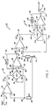
- FIG. 3 a functional block diagram of the flux squared sensor 23 is shown, comprised of sensors 24 and 26. Sensors 24 is identical in construction to sensor 26 in this embodiment. Sensor 23 has a first Hall generator subassembly 30, and a second Hall generator subassembly 32. First subassembly 30 has a first amplifier 34, a Hall generator unit or sensor 24, and a second amplifier, or transimpedance amplifier 38. Second assembly 32 also has a first amplifier 40, a Hall generator unit or sensor 26, and a second amplifier 44.
- amplifier 34 has a top positive input terminal 46, a bottom negative input terminal 48, and an output terminal 50.
- a connector 52 extends from top positive input terminal 46 to a terminal 54 for a reference voltage supply.
- Hall generator unit 24 has a first left positive terminal 56, a second right positive terminal 58, a first left negative terminal 60, and a second right negative terminal 62.
- a connector 64 extends from second positive terminal 58 to amplifier output terminal 50.
- a connector 66 extends from amplifier negative input terminal 48, through a junction 68, through a resistor 70, through a junction 72, to ground 74.
- a connector 76 extends from Hall generator first negative terminal 60 to junction 68.
- Amplifier 38 has a bottom positive input terminal 78, a top negative input terminal 80, an an output terminal 82.
- a connector 84 extends from bottom positive input terminal 78, to first left positive input terminal 56.
- a connector 85 extends from negative input terminal 80, through a junction 88, to the Hall generator output terminal 62.
- a connector 90 extends from amplifier output terminal 82 through a junction 92, through a resistor 94 to junction 88.
- amplifier 40 has a top positive input terminal 96, a bottom negative input terminal 98, and an outlet terminal 100.
- a connector 102 extends from top positive input terminal 96 to terminal 92.
- Hall generator unit 26 has a first left positive terminal 104, a second bottom positive terminal 106, a first left negative terminal 108, and a second right negative terminal 110.
- a connector 112 extends from second positive terminal 106 to amplifier outlet terminal 100.
- a connector 114 extends from amplifier negative input terminal 98, through a junction 116, through a resistor 118, and through a junction 72, which is connected to ground 74.
- a connector 120 extends from Hall generator first negative terminal 108 to junction 116.
- Amplifier 44 has a bottom positive input terminal 122, a top negative input terminal 124, and an output terminal 126.
- a connector 128 extends from bottom positive input terminal 122 to first left positive input terminal 104.
- a connector 130 extends from negative input terminal 124, through a junction 132, to output terminal 110.
- a connector 134 extends from amplifier output terminal 126 through a junction 136, through a resistor 138, to junction 132.
- a connector 140 extends from terminal 136 to a terminal 142 for the voltage output (Vout).
- Figure 3 illustrates a function diagram of the flux squared sensor 23.
- Two Hall generator subassemblies 30, 32 within a common magnetic field, are cascaded.
- the output of the first device 30 is converted to a control current (I H2 ) proportional to flux density for the second device 32.
- the resultant output at terminal 142 of device 32 is proportional to flux density squared, which in turn is proportional to the actuator force.
- a voltage controlled current source 34 fed by a stable, constant voltage delivers constant current (I H1 ) through the first Hall generator (HG1) 24.
- This current is given by:
- actuator 10 The advantages of actuator 10 are indicated hereafter.
- sensor 23 provides a feedback signal which is proportional to force.
- sensor 23 does not require non-linear signal conditioning elements to provide an output proportional to force.
- sensor 23 provides an increase in force accuracy in an all-analog system as compared to prior art sensors.
- sensor 23 reduces computational overhead when used in a digital or hybrid controller.
- actuator 10 can operate in a low-quiescent power configuration without using non-linear circuit elements or algorithms.
Landscapes
- Physics & Mathematics (AREA)
- Condensed Matter Physics & Semiconductors (AREA)
- General Physics & Mathematics (AREA)
- Transmission And Conversion Of Sensor Element Output (AREA)
- Control Of Linear Motors (AREA)
- Force Measurement Appropriate To Specific Purposes (AREA)
- Measuring Magnetic Variables (AREA)
Claims (6)
- Capteur de flux destiné à une utilisation dans un champ de flux pour capter une densité de flux, caractérisé par :a) un premier amplificateur (34) comprenant une première borne d'entrée (46) pour recevoir une tension de référence et comprenant une borne de sortie (50) ;b) une première unité de générateur à effet Hall (24) comprenant une première borne d'entrée (58) connectée à la borne de sortie (50) du premier amplificateur (34) pour recevoir un courant commandé par une tension de référence et comprenant une première borne de sortie (56) ;c) un second amplificateur (38) comprenant une première borne d'entrée (78) connectée à la seconde borne de sortie (56) de la première unité de générateur à effet Hall (24) et comprenant une borne de sortie (82) pour appliquer une tension de sortie ;d) un troisième amplificateur (40) comprenant une première borne d'entrée (96) connectée à la borne de sortie (82) du second amplificateur (38) et comprenant une borne de sortie (100) ;e) une seconde unité de générateur à effet Hall (26) comprenant une première borne d'entrée (106) connectée à la borne de sortie (100) du troisième amplificateur (40) pour recevoir un courant à flux modulé et comprenant une borne de sortie (104) ; etf) un quatrième amplificateur (44) comprenant une première borne d'entrée (122) connectée à la borne de sortie (104) de la seconde unité de générateur à effet Hall (26) et comprenant une borne de sortie (126) pour appliquer une tension de sortie.
- Capteur de flux selon la revendication 1, caractérisé par :a) une armature (16) ; etb) un stator (12) comprenant un retour magnétique (22) ;c) ledit retour magnétique (22) comportant une première partie d'extrémité (25) munie d'une première bobine (18) et comportant une seconde partie d'extrémité (27) munie d'une seconde bobine (20) pour former une voie de flux magnétique avec un champ de flux magnétique présentant une certaine densité de flux ;d) lesdites parties d'extrémité (25, 27) étant espacées de façon sélective de l'armature (16) ; ete) ladite première partie d'extrémité (25) supportant la première unité de générateur à effet Hall (24) et ladite seconde partie d'extrémité (27) supportant la seconde unité de générateur à effet Hall (26).
- Capteur de flux selon la revendication 2, caractérisé en ce que :a) le stator (12) applique une certaine force sur l'armature (16) lorsqu'il est activé, ladite force est fonction d'un courant appliqué à la première bobine (18) et à la seconde bobine (20) et ladite force est proportionnelle au carré de la densité de flux et ledit carré de la densité de flux est proportionnel à la tension de sortie ; et ladite tension de sortie produit un signal de retour pour la commande du courant appliqué d'où il résulte que la force appliquée est une force d'une valeur connue susceptible de se répéter pour un niveau appliqué du courant au travers des bobines ; et dans lequelb) ladite armature (16) comporte une première face qui fait face audit stator (12) et une seconde face qui fait face à un second stator (14) d'un second capteur de flux.
- Capteur de flux selon l'une quelconque des revendications précédentes, caractérisé en ce que :a) un premier sous-ensemble de générateur à effet Hall (30) comprend le premier amplificateur (34), la première unité de générateur à effet Hall (24) et le second amplificateur (38) ; etb) un second sous-ensemble de générateur à effet Hall (32) comprend le troisième amplificateur (40), la seconde unité de générateur à effet Hall (26) et le quatrième amplificateur (44).
- Capteur de flux selon la revendication 4 lorsqu'elle dépend de la revendication 2 ou 3, caractérisé en ce que ladite première partie d'extrémité (25) et ladite seconde partie d'extrémité (27) forment respectivement un premier entrefer et un second entrefer par rapport à l'armature (16) et ledit premier sous-ensemble de générateur à effet Hall (30) ainsi que ledit second sous-ensemble de générateur à effet Hall (32) sont respectivement partiellement disposés dans ledit premier entrefer et dans ledit second entrefer.
- Capteur de flux selon l'une quelconque des revendications 2 à 5, caractérisé en ce qu'à la fois les première et seconde unités de générateur à effet Hall (24, 26) sont exposées au même flux magnétique qui circule dans un circuit magnétique comprenant ledit stator (12) et ladite armature (16).
Applications Claiming Priority (2)
| Application Number | Priority Date | Filing Date | Title |
|---|---|---|---|
| US246129 | 1988-09-19 | ||
| US07/246,129 US4882512A (en) | 1988-09-19 | 1988-09-19 | Electromagnetic force sensor |
Publications (3)
| Publication Number | Publication Date |
|---|---|
| EP0360166A2 EP0360166A2 (fr) | 1990-03-28 |
| EP0360166A3 EP0360166A3 (fr) | 1991-04-10 |
| EP0360166B1 true EP0360166B1 (fr) | 1993-09-15 |
Family
ID=22929418
Family Applications (1)
| Application Number | Title | Priority Date | Filing Date |
|---|---|---|---|
| EP89117093A Expired - Lifetime EP0360166B1 (fr) | 1988-09-19 | 1989-09-15 | Capteur de force électromagnétique |
Country Status (6)
| Country | Link |
|---|---|
| US (1) | US4882512A (fr) |
| EP (1) | EP0360166B1 (fr) |
| JP (1) | JPH02186284A (fr) |
| CA (1) | CA1309140C (fr) |
| DE (1) | DE68909157T2 (fr) |
| ES (1) | ES2043999T3 (fr) |
Families Citing this family (9)
| Publication number | Priority date | Publication date | Assignee | Title |
|---|---|---|---|---|
| US5294757A (en) * | 1990-07-18 | 1994-03-15 | Otis Elevator Company | Active vibration control system for an elevator, which reduces horizontal and rotational forces acting on the car |
| US5322144A (en) * | 1990-07-18 | 1994-06-21 | Otis Elevator Company | Active control of elevator platform |
| US5308938A (en) * | 1990-07-18 | 1994-05-03 | Otis Elevator Company | Elevator active suspension system |
| US5321217A (en) * | 1990-07-18 | 1994-06-14 | Otis Elevator Company | Apparatus and method for controlling an elevator horizontal suspension |
| US5115192A (en) * | 1990-11-06 | 1992-05-19 | Nova Corporation Of Alberta | Magnetic displacement transducer with saturation compensation |
| US6753664B2 (en) | 2001-03-22 | 2004-06-22 | Creo Products Inc. | Method for linearization of an actuator via force gradient modification |
| DE102005014509B4 (de) * | 2005-03-30 | 2007-09-13 | Austriamicrosystems Ag | Sensoranordnung und Verfahren zur Bestimmung eines Drehwinkels |
| CN102519633B (zh) * | 2011-11-30 | 2014-07-16 | 浙江大学 | 磁弹磁电效应式应力监测装置 |
| US9664753B2 (en) * | 2014-03-27 | 2017-05-30 | Stmicroelectronics S.R.L. | Hall-effect-based magnetic field sensor having an improved output bandwidth |
Family Cites Families (6)
| Publication number | Priority date | Publication date | Assignee | Title |
|---|---|---|---|---|
| DE3110107A1 (de) * | 1981-03-16 | 1982-09-23 | Mannesmann Rexroth GmbH, 8770 Lohr | Kraftmessverfahren und kraftmessvorrichtung zur steuerung des krafthebers eines ackerschleppers |
| DE3435455A1 (de) * | 1984-09-27 | 1986-03-27 | Nukem Gmbh, 6450 Hanau | Vorrichtung mit zwei hallgeneratoren zur messung der gradienten magnetischer felder |
| JPS61194885A (ja) * | 1985-02-25 | 1986-08-29 | Seiko Instr & Electronics Ltd | 磁気センサ |
| US4629262A (en) * | 1985-06-24 | 1986-12-16 | Sperry Corporation | Position sensor for magnetic suspension and pointing system |
| US4642501A (en) * | 1985-10-15 | 1987-02-10 | Sperry Corporation | Magnetic suspension and pointing system with flux feedback linearization |
| DE3627127A1 (de) * | 1986-08-06 | 1988-02-18 | Pfister Gmbh | Membran fuer kraftmesseinrichtungen |
-
1988
- 1988-09-19 US US07/246,129 patent/US4882512A/en not_active Expired - Lifetime
-
1989
- 1989-09-15 EP EP89117093A patent/EP0360166B1/fr not_active Expired - Lifetime
- 1989-09-15 DE DE89117093T patent/DE68909157T2/de not_active Expired - Lifetime
- 1989-09-15 ES ES89117093T patent/ES2043999T3/es not_active Expired - Lifetime
- 1989-09-18 CA CA000611715A patent/CA1309140C/fr not_active Expired - Fee Related
- 1989-09-19 JP JP1240919A patent/JPH02186284A/ja active Pending
Also Published As
| Publication number | Publication date |
|---|---|
| CA1309140C (fr) | 1992-10-20 |
| JPH02186284A (ja) | 1990-07-20 |
| US4882512A (en) | 1989-11-21 |
| EP0360166A2 (fr) | 1990-03-28 |
| DE68909157D1 (de) | 1993-10-21 |
| ES2043999T3 (es) | 1994-01-01 |
| EP0360166A3 (fr) | 1991-04-10 |
| DE68909157T2 (de) | 1994-02-03 |
Similar Documents
| Publication | Publication Date | Title |
|---|---|---|
| EP0222513B1 (fr) | Suspension magnétique avec linéarisation par rétroaction de flux | |
| EP0218318B1 (fr) | Détecteur de position d'une pièce suspendue avec des moyens magnétiques | |
| US4093917A (en) | Velocity measurement system | |
| US5329416A (en) | Active broadband magnetic flux rate feedback sensing arrangement | |
| EP0133695B1 (fr) | Système de capteurs pour mesurer des paramètres | |
| US6348788B1 (en) | High resolution current sensing apparatus | |
| US4727323A (en) | Magneto-resistive differential sensor system | |
| EP0357013A2 (fr) | Circuit pour mesurer un champ magnétique | |
| EP0360166B1 (fr) | Capteur de force électromagnétique | |
| WO1995010710A2 (fr) | Dispositif electro-hydraulique de commande et de dosage de fluides | |
| US4585978A (en) | Magnetostrictive actuator with feedback compensation | |
| US4975643A (en) | Measurement and control of magnetostrictive transducer motion using strain sensors | |
| US4872339A (en) | Mass flow meter | |
| US3613021A (en) | Hall-effect amplifying device with temperature compensated characteristic | |
| US5124879A (en) | Electrostatic drive device and circuit for controlling same | |
| JP3081751B2 (ja) | 電気量測定装置 | |
| US4538465A (en) | Electronic transmitter for transmitting pressure values of industrial process fluids | |
| JPH02163625A (ja) | トルク測定装置 | |
| US6204657B1 (en) | Temperature compensated closed-loop hall effect current transformer | |
| JP2632451B2 (ja) | 力学量検知器 | |
| GB1311790A (en) | Positioning means | |
| US3882731A (en) | Torquer scale factor temperature correction means | |
| US2956212A (en) | Transducing apparatus | |
| SU1068820A1 (ru) | Компенсационный акселерометр | |
| Haeussermann | Velocity measurement system |
Legal Events
| Date | Code | Title | Description |
|---|---|---|---|
| PUAI | Public reference made under article 153(3) epc to a published international application that has entered the european phase |
Free format text: ORIGINAL CODE: 0009012 |
|
| AK | Designated contracting states |
Kind code of ref document: A2 Designated state(s): DE ES FR GB IT NL |
|
| PUAL | Search report despatched |
Free format text: ORIGINAL CODE: 0009013 |
|
| AK | Designated contracting states |
Kind code of ref document: A3 Designated state(s): DE ES FR GB IT NL |
|
| 17P | Request for examination filed |
Effective date: 19910826 |
|
| 17Q | First examination report despatched |
Effective date: 19921111 |
|
| GRAA | (expected) grant |
Free format text: ORIGINAL CODE: 0009210 |
|
| AK | Designated contracting states |
Kind code of ref document: B1 Designated state(s): DE ES FR GB IT NL |
|
| REF | Corresponds to: |
Ref document number: 68909157 Country of ref document: DE Date of ref document: 19931021 |
|
| ET | Fr: translation filed | ||
| ITF | It: translation for a ep patent filed | ||
| REG | Reference to a national code |
Ref country code: ES Ref legal event code: FG2A Ref document number: 2043999 Country of ref document: ES Kind code of ref document: T3 |
|
| PLBE | No opposition filed within time limit |
Free format text: ORIGINAL CODE: 0009261 |
|
| STAA | Information on the status of an ep patent application or granted ep patent |
Free format text: STATUS: NO OPPOSITION FILED WITHIN TIME LIMIT |
|
| 26N | No opposition filed | ||
| ITTA | It: last paid annual fee | ||
| REG | Reference to a national code |
Ref country code: GB Ref legal event code: IF02 |
|
| PGFP | Annual fee paid to national office [announced via postgrant information from national office to epo] |
Ref country code: NL Payment date: 20050808 Year of fee payment: 17 |
|
| PGFP | Annual fee paid to national office [announced via postgrant information from national office to epo] |
Ref country code: ES Payment date: 20050919 Year of fee payment: 17 |
|
| PGFP | Annual fee paid to national office [announced via postgrant information from national office to epo] |
Ref country code: IT Payment date: 20060930 Year of fee payment: 18 |
|
| PG25 | Lapsed in a contracting state [announced via postgrant information from national office to epo] |
Ref country code: NL Free format text: LAPSE BECAUSE OF NON-PAYMENT OF DUE FEES Effective date: 20070401 |
|
| NLV4 | Nl: lapsed or anulled due to non-payment of the annual fee |
Effective date: 20070401 |
|
| REG | Reference to a national code |
Ref country code: ES Ref legal event code: FD2A Effective date: 20060916 |
|
| PG25 | Lapsed in a contracting state [announced via postgrant information from national office to epo] |
Ref country code: ES Free format text: LAPSE BECAUSE OF NON-PAYMENT OF DUE FEES Effective date: 20060916 |
|
| PGFP | Annual fee paid to national office [announced via postgrant information from national office to epo] |
Ref country code: FR Payment date: 20080904 Year of fee payment: 20 |
|
| PGFP | Annual fee paid to national office [announced via postgrant information from national office to epo] |
Ref country code: GB Payment date: 20080808 Year of fee payment: 20 |
|
| PGFP | Annual fee paid to national office [announced via postgrant information from national office to epo] |
Ref country code: DE Payment date: 20080930 Year of fee payment: 20 |
|
| PG25 | Lapsed in a contracting state [announced via postgrant information from national office to epo] |
Ref country code: IT Free format text: LAPSE BECAUSE OF NON-PAYMENT OF DUE FEES Effective date: 20070915 |
|
| REG | Reference to a national code |
Ref country code: GB Ref legal event code: PE20 Expiry date: 20090914 |
|
| PG25 | Lapsed in a contracting state [announced via postgrant information from national office to epo] |
Ref country code: GB Free format text: LAPSE BECAUSE OF EXPIRATION OF PROTECTION Effective date: 20090914 |
|
| P01 | Opt-out of the competence of the unified patent court (upc) registered |
Effective date: 20230525 |