EP0360116A1 - Röntgen-Verstärkerschirm mit verbessertem Verhältnis von Bildempfindlichkeit zu Schärfe - Google Patents
Röntgen-Verstärkerschirm mit verbessertem Verhältnis von Bildempfindlichkeit zu Schärfe Download PDFInfo
- Publication number
- EP0360116A1 EP0360116A1 EP89116756A EP89116756A EP0360116A1 EP 0360116 A1 EP0360116 A1 EP 0360116A1 EP 89116756 A EP89116756 A EP 89116756A EP 89116756 A EP89116756 A EP 89116756A EP 0360116 A1 EP0360116 A1 EP 0360116A1
- Authority
- EP
- European Patent Office
- Prior art keywords
- intensifying screen
- radiation
- further characterized
- screen according
- fluorescent layer
- Prior art date
- Legal status (The legal status is an assumption and is not a legal conclusion. Google has not performed a legal analysis and makes no representation as to the accuracy of the status listed.)
- Granted
Links
- 238000003384 imaging method Methods 0.000 title description 20
- 230000005670 electromagnetic radiation Effects 0.000 claims abstract description 44
- 230000005855 radiation Effects 0.000 claims abstract description 34
- 229920000728 polyester Polymers 0.000 claims description 96
- 239000011325 microbead Substances 0.000 claims description 79
- -1 silver halide Chemical class 0.000 claims description 67
- 229920002301 cellulose acetate Polymers 0.000 claims description 60
- 229910052709 silver Inorganic materials 0.000 claims description 26
- 239000004332 silver Substances 0.000 claims description 26
- OAICVXFJPJFONN-UHFFFAOYSA-N Phosphorus Chemical compound [P] OAICVXFJPJFONN-UHFFFAOYSA-N 0.000 claims description 18
- 230000003287 optical effect Effects 0.000 claims description 16
- 238000006243 chemical reaction Methods 0.000 claims description 14
- OYPRJOBELJOOCE-UHFFFAOYSA-N Calcium Chemical compound [Ca] OYPRJOBELJOOCE-UHFFFAOYSA-N 0.000 claims description 13
- 229910052791 calcium Inorganic materials 0.000 claims description 13
- 239000011575 calcium Substances 0.000 claims description 13
- PBYZMCDFOULPGH-UHFFFAOYSA-N tungstate Chemical compound [O-][W]([O-])(=O)=O PBYZMCDFOULPGH-UHFFFAOYSA-N 0.000 claims description 13
- 238000001228 spectrum Methods 0.000 claims description 10
- 230000015572 biosynthetic process Effects 0.000 claims description 8
- 238000012546 transfer Methods 0.000 claims description 8
- 239000011324 bead Substances 0.000 claims description 7
- 229920000139 polyethylene terephthalate Polymers 0.000 claims description 4
- 239000005020 polyethylene terephthalate Substances 0.000 claims description 4
- 229920003229 poly(methyl methacrylate) Polymers 0.000 claims description 3
- 239000004926 polymethyl methacrylate Substances 0.000 claims description 3
- 125000000218 acetic acid group Chemical group C(C)(=O)* 0.000 claims 1
- 239000000203 mixture Substances 0.000 description 54
- 229940081735 acetylcellulose Drugs 0.000 description 51
- LYCAIKOWRPUZTN-UHFFFAOYSA-N Ethylene glycol Chemical compound OCCO LYCAIKOWRPUZTN-UHFFFAOYSA-N 0.000 description 34
- 239000011159 matrix material Substances 0.000 description 24
- 229910052761 rare earth metal Inorganic materials 0.000 description 24
- 239000000839 emulsion Substances 0.000 description 22
- 239000000463 material Substances 0.000 description 21
- 238000010276 construction Methods 0.000 description 20
- GWEVSGVZZGPLCZ-UHFFFAOYSA-N Titan oxide Chemical compound O=[Ti]=O GWEVSGVZZGPLCZ-UHFFFAOYSA-N 0.000 description 16
- 239000002245 particle Substances 0.000 description 16
- 150000002910 rare earth metals Chemical class 0.000 description 16
- 238000010521 absorption reaction Methods 0.000 description 15
- 238000000034 method Methods 0.000 description 15
- 239000000758 substrate Substances 0.000 description 15
- 230000008901 benefit Effects 0.000 description 13
- 229920002678 cellulose Polymers 0.000 description 12
- 230000009977 dual effect Effects 0.000 description 11
- 229920001634 Copolyester Polymers 0.000 description 10
- TZCXTZWJZNENPQ-UHFFFAOYSA-L barium sulfate Chemical compound [Ba+2].[O-]S([O-])(=O)=O TZCXTZWJZNENPQ-UHFFFAOYSA-L 0.000 description 9
- 238000001125 extrusion Methods 0.000 description 9
- 230000001965 increasing effect Effects 0.000 description 9
- 239000000049 pigment Substances 0.000 description 9
- 239000011230 binding agent Substances 0.000 description 8
- 238000005266 casting Methods 0.000 description 8
- 239000000835 fiber Substances 0.000 description 8
- 239000007789 gas Substances 0.000 description 8
- WGCNASOHLSPBMP-UHFFFAOYSA-N hydroxyacetaldehyde Natural products OCC=O WGCNASOHLSPBMP-UHFFFAOYSA-N 0.000 description 8
- 238000002156 mixing Methods 0.000 description 8
- 238000012545 processing Methods 0.000 description 8
- 229910052688 Gadolinium Inorganic materials 0.000 description 7
- 150000002148 esters Chemical class 0.000 description 7
- 239000012463 white pigment Substances 0.000 description 7
- 206010073306 Exposure to radiation Diseases 0.000 description 6
- OFOBLEOULBTSOW-UHFFFAOYSA-N Malonic acid Chemical compound OC(=O)CC(O)=O OFOBLEOULBTSOW-UHFFFAOYSA-N 0.000 description 6
- 239000007795 chemical reaction product Substances 0.000 description 6
- 230000000694 effects Effects 0.000 description 6
- 230000006870 function Effects 0.000 description 6
- UIWYJDYFSGRHKR-UHFFFAOYSA-N gadolinium atom Chemical compound [Gd] UIWYJDYFSGRHKR-UHFFFAOYSA-N 0.000 description 6
- 230000009477 glass transition Effects 0.000 description 6
- 230000008569 process Effects 0.000 description 6
- VTYYLEPIZMXCLO-UHFFFAOYSA-L Calcium carbonate Chemical compound [Ca+2].[O-]C([O-])=O VTYYLEPIZMXCLO-UHFFFAOYSA-L 0.000 description 5
- 229910052771 Terbium Inorganic materials 0.000 description 5
- 229910052799 carbon Inorganic materials 0.000 description 5
- 238000000576 coating method Methods 0.000 description 5
- 239000000155 melt Substances 0.000 description 5
- 239000000047 product Substances 0.000 description 5
- 239000007787 solid Substances 0.000 description 5
- 210000001519 tissue Anatomy 0.000 description 5
- 239000011800 void material Substances 0.000 description 5
- 229910052727 yttrium Inorganic materials 0.000 description 5
- VWQVUPCCIRVNHF-UHFFFAOYSA-N yttrium atom Chemical compound [Y] VWQVUPCCIRVNHF-UHFFFAOYSA-N 0.000 description 5
- OKTJSMMVPCPJKN-UHFFFAOYSA-N Carbon Chemical compound [C] OKTJSMMVPCPJKN-UHFFFAOYSA-N 0.000 description 4
- 229910052765 Lutetium Inorganic materials 0.000 description 4
- 239000004743 Polypropylene Substances 0.000 description 4
- KKEYFWRCBNTPAC-UHFFFAOYSA-N Terephthalic acid Chemical compound OC(=O)C1=CC=C(C(O)=O)C=C1 KKEYFWRCBNTPAC-UHFFFAOYSA-N 0.000 description 4
- 229910052775 Thulium Inorganic materials 0.000 description 4
- YIMQCDZDWXUDCA-UHFFFAOYSA-N [4-(hydroxymethyl)cyclohexyl]methanol Chemical compound OCC1CCC(CO)CC1 YIMQCDZDWXUDCA-UHFFFAOYSA-N 0.000 description 4
- 239000011358 absorbing material Substances 0.000 description 4
- 239000002253 acid Substances 0.000 description 4
- 239000000654 additive Substances 0.000 description 4
- 229910052798 chalcogen Inorganic materials 0.000 description 4
- 150000001787 chalcogens Chemical class 0.000 description 4
- 239000003086 colorant Substances 0.000 description 4
- WOZVHXUHUFLZGK-UHFFFAOYSA-N dimethyl terephthalate Chemical compound COC(=O)C1=CC=C(C(=O)OC)C=C1 WOZVHXUHUFLZGK-UHFFFAOYSA-N 0.000 description 4
- 239000006185 dispersion Substances 0.000 description 4
- 239000000975 dye Substances 0.000 description 4
- OHSVLFRHMCKCQY-UHFFFAOYSA-N lutetium atom Chemical compound [Lu] OHSVLFRHMCKCQY-UHFFFAOYSA-N 0.000 description 4
- GZCRRIHWUXGPOV-UHFFFAOYSA-N terbium atom Chemical compound [Tb] GZCRRIHWUXGPOV-UHFFFAOYSA-N 0.000 description 4
- 239000010936 titanium Substances 0.000 description 4
- PXGZQGDTEZPERC-UHFFFAOYSA-N 1,4-cyclohexanedicarboxylic acid Chemical compound OC(=O)C1CCC(C(O)=O)CC1 PXGZQGDTEZPERC-UHFFFAOYSA-N 0.000 description 3
- 229910052684 Cerium Inorganic materials 0.000 description 3
- YMWUJEATGCHHMB-UHFFFAOYSA-N Dichloromethane Chemical compound ClCCl YMWUJEATGCHHMB-UHFFFAOYSA-N 0.000 description 3
- OKKJLVBELUTLKV-UHFFFAOYSA-N Methanol Chemical compound OC OKKJLVBELUTLKV-UHFFFAOYSA-N 0.000 description 3
- DNIAPMSPPWPWGF-UHFFFAOYSA-N Propylene glycol Chemical compound CC(O)CO DNIAPMSPPWPWGF-UHFFFAOYSA-N 0.000 description 3
- 229910052769 Ytterbium Inorganic materials 0.000 description 3
- 150000007513 acids Chemical class 0.000 description 3
- QVGXLLKOCUKJST-UHFFFAOYSA-N atomic oxygen Chemical compound [O] QVGXLLKOCUKJST-UHFFFAOYSA-N 0.000 description 3
- 210000000481 breast Anatomy 0.000 description 3
- 230000015556 catabolic process Effects 0.000 description 3
- 230000008859 change Effects 0.000 description 3
- 239000011248 coating agent Substances 0.000 description 3
- 230000006835 compression Effects 0.000 description 3
- 238000007906 compression Methods 0.000 description 3
- 230000003247 decreasing effect Effects 0.000 description 3
- 238000006731 degradation reaction Methods 0.000 description 3
- 238000010586 diagram Methods 0.000 description 3
- MTHSVFCYNBDYFN-UHFFFAOYSA-N diethylene glycol Chemical compound OCCOCCO MTHSVFCYNBDYFN-UHFFFAOYSA-N 0.000 description 3
- 238000009826 distribution Methods 0.000 description 3
- 230000001747 exhibiting effect Effects 0.000 description 3
- 238000010348 incorporation Methods 0.000 description 3
- 238000002844 melting Methods 0.000 description 3
- 229910052758 niobium Inorganic materials 0.000 description 3
- 239000010955 niobium Substances 0.000 description 3
- GUCVJGMIXFAOAE-UHFFFAOYSA-N niobium atom Chemical compound [Nb] GUCVJGMIXFAOAE-UHFFFAOYSA-N 0.000 description 3
- 229910052760 oxygen Inorganic materials 0.000 description 3
- 239000001301 oxygen Substances 0.000 description 3
- 230000000737 periodic effect Effects 0.000 description 3
- 229920003023 plastic Polymers 0.000 description 3
- 239000004033 plastic Substances 0.000 description 3
- 229920000642 polymer Polymers 0.000 description 3
- 229920001155 polypropylene Polymers 0.000 description 3
- 229920002635 polyurethane Polymers 0.000 description 3
- 238000011160 research Methods 0.000 description 3
- 239000000126 substance Substances 0.000 description 3
- QPFMBZIOSGYJDE-UHFFFAOYSA-N 1,1,2,2-tetrachloroethane Chemical compound ClC(Cl)C(Cl)Cl QPFMBZIOSGYJDE-UHFFFAOYSA-N 0.000 description 2
- IJGRMHOSHXDMSA-UHFFFAOYSA-N Atomic nitrogen Chemical compound N#N IJGRMHOSHXDMSA-UHFFFAOYSA-N 0.000 description 2
- 229930185605 Bisphenol Natural products 0.000 description 2
- 229920002284 Cellulose triacetate Polymers 0.000 description 2
- LFQSCWFLJHTTHZ-UHFFFAOYSA-N Ethanol Chemical compound CCO LFQSCWFLJHTTHZ-UHFFFAOYSA-N 0.000 description 2
- 229910052693 Europium Inorganic materials 0.000 description 2
- WYURNTSHIVDZCO-UHFFFAOYSA-N Tetrahydrofuran Chemical compound C1CCOC1 WYURNTSHIVDZCO-UHFFFAOYSA-N 0.000 description 2
- 108010074506 Transfer Factor Proteins 0.000 description 2
- XLOMVQKBTHCTTD-UHFFFAOYSA-N Zinc monoxide Chemical compound [Zn]=O XLOMVQKBTHCTTD-UHFFFAOYSA-N 0.000 description 2
- NNLVGZFZQQXQNW-ADJNRHBOSA-N [(2r,3r,4s,5r,6s)-4,5-diacetyloxy-3-[(2s,3r,4s,5r,6r)-3,4,5-triacetyloxy-6-(acetyloxymethyl)oxan-2-yl]oxy-6-[(2r,3r,4s,5r,6s)-4,5,6-triacetyloxy-2-(acetyloxymethyl)oxan-3-yl]oxyoxan-2-yl]methyl acetate Chemical compound O([C@@H]1O[C@@H]([C@H]([C@H](OC(C)=O)[C@H]1OC(C)=O)O[C@H]1[C@@H]([C@@H](OC(C)=O)[C@H](OC(C)=O)[C@@H](COC(C)=O)O1)OC(C)=O)COC(=O)C)[C@@H]1[C@@H](COC(C)=O)O[C@@H](OC(C)=O)[C@H](OC(C)=O)[C@H]1OC(C)=O NNLVGZFZQQXQNW-ADJNRHBOSA-N 0.000 description 2
- 125000002777 acetyl group Chemical group [H]C([H])([H])C(*)=O 0.000 description 2
- 125000001931 aliphatic group Chemical group 0.000 description 2
- 125000005250 alkyl acrylate group Chemical group 0.000 description 2
- 229910052782 aluminium Inorganic materials 0.000 description 2
- XAGFODPZIPBFFR-UHFFFAOYSA-N aluminium Chemical compound [Al] XAGFODPZIPBFFR-UHFFFAOYSA-N 0.000 description 2
- 238000000429 assembly Methods 0.000 description 2
- 230000000712 assembly Effects 0.000 description 2
- 230000002457 bidirectional effect Effects 0.000 description 2
- IISBACLAFKSPIT-UHFFFAOYSA-N bisphenol A Chemical group C=1C=C(O)C=CC=1C(C)(C)C1=CC=C(O)C=C1 IISBACLAFKSPIT-UHFFFAOYSA-N 0.000 description 2
- 238000007664 blowing Methods 0.000 description 2
- 210000000988 bone and bone Anatomy 0.000 description 2
- 229910000019 calcium carbonate Inorganic materials 0.000 description 2
- 125000004432 carbon atom Chemical group C* 0.000 description 2
- 238000001816 cooling Methods 0.000 description 2
- 229920001577 copolymer Polymers 0.000 description 2
- 238000002425 crystallisation Methods 0.000 description 2
- 230000008025 crystallization Effects 0.000 description 2
- 150000001991 dicarboxylic acids Chemical class 0.000 description 2
- 235000012489 doughnuts Nutrition 0.000 description 2
- 238000004945 emulsification Methods 0.000 description 2
- OGPBJKLSAFTDLK-UHFFFAOYSA-N europium atom Chemical compound [Eu] OGPBJKLSAFTDLK-UHFFFAOYSA-N 0.000 description 2
- 238000011156 evaluation Methods 0.000 description 2
- 229910052736 halogen Inorganic materials 0.000 description 2
- 229910010272 inorganic material Inorganic materials 0.000 description 2
- 239000011147 inorganic material Substances 0.000 description 2
- QQVIHTHCMHWDBS-UHFFFAOYSA-N isophthalic acid Chemical compound OC(=O)C1=CC=CC(C(O)=O)=C1 QQVIHTHCMHWDBS-UHFFFAOYSA-N 0.000 description 2
- 230000031700 light absorption Effects 0.000 description 2
- 230000000670 limiting effect Effects 0.000 description 2
- 239000004973 liquid crystal related substance Substances 0.000 description 2
- 238000005259 measurement Methods 0.000 description 2
- 230000008018 melting Effects 0.000 description 2
- 150000002734 metacrylic acid derivatives Chemical class 0.000 description 2
- 238000000465 moulding Methods 0.000 description 2
- KYTZHLUVELPASH-UHFFFAOYSA-N naphthalene-1,2-dicarboxylic acid Chemical compound C1=CC=CC2=C(C(O)=O)C(C(=O)O)=CC=C21 KYTZHLUVELPASH-UHFFFAOYSA-N 0.000 description 2
- 239000002667 nucleating agent Substances 0.000 description 2
- 229920000620 organic polymer Polymers 0.000 description 2
- 230000035699 permeability Effects 0.000 description 2
- 230000000704 physical effect Effects 0.000 description 2
- 239000002985 plastic film Substances 0.000 description 2
- 229920006255 plastic film Polymers 0.000 description 2
- 229920002451 polyvinyl alcohol Polymers 0.000 description 2
- 229910001404 rare earth metal oxide Inorganic materials 0.000 description 2
- 230000009467 reduction Effects 0.000 description 2
- 238000002310 reflectometry Methods 0.000 description 2
- 230000003595 spectral effect Effects 0.000 description 2
- UBXAKNTVXQMEAG-UHFFFAOYSA-L strontium sulfate Chemical compound [Sr+2].[O-]S([O-])(=O)=O UBXAKNTVXQMEAG-UHFFFAOYSA-L 0.000 description 2
- HMNUYYJYMOXWTN-UHFFFAOYSA-J strontium;barium(2+);disulfate Chemical compound [Sr+2].[Ba+2].[O-]S([O-])(=O)=O.[O-]S([O-])(=O)=O HMNUYYJYMOXWTN-UHFFFAOYSA-J 0.000 description 2
- 229920001169 thermoplastic Polymers 0.000 description 2
- 229920002725 thermoplastic elastomer Polymers 0.000 description 2
- 239000004416 thermosoftening plastic Substances 0.000 description 2
- 238000002834 transmittance Methods 0.000 description 2
- NAWDYIZEMPQZHO-UHFFFAOYSA-N ytterbium Chemical compound [Yb] NAWDYIZEMPQZHO-UHFFFAOYSA-N 0.000 description 2
- SMZOUWXMTYCWNB-UHFFFAOYSA-N 2-(2-methoxy-5-methylphenyl)ethanamine Chemical compound COC1=CC=C(C)C=C1CCN SMZOUWXMTYCWNB-UHFFFAOYSA-N 0.000 description 1
- OONPLQJHBJXVBP-UHFFFAOYSA-N 3-(2-phenylethenyl)phthalic acid Chemical compound OC(=O)C1=CC=CC(C=CC=2C=CC=CC=2)=C1C(O)=O OONPLQJHBJXVBP-UHFFFAOYSA-N 0.000 description 1
- SBBQDUFLZGOASY-OWOJBTEDSA-N 4-[(e)-2-(4-carboxyphenyl)ethenyl]benzoic acid Chemical compound C1=CC(C(=O)O)=CC=C1\C=C\C1=CC=C(C(O)=O)C=C1 SBBQDUFLZGOASY-OWOJBTEDSA-N 0.000 description 1
- QTBSBXVTEAMEQO-UHFFFAOYSA-M Acetate Chemical compound CC([O-])=O QTBSBXVTEAMEQO-UHFFFAOYSA-M 0.000 description 1
- 229920008347 Cellulose acetate propionate Polymers 0.000 description 1
- RYGMFSIKBFXOCR-UHFFFAOYSA-N Copper Chemical compound [Cu] RYGMFSIKBFXOCR-UHFFFAOYSA-N 0.000 description 1
- 229910052692 Dysprosium Inorganic materials 0.000 description 1
- 229910052691 Erbium Inorganic materials 0.000 description 1
- 229910052689 Holmium Inorganic materials 0.000 description 1
- DGAQECJNVWCQMB-PUAWFVPOSA-M Ilexoside XXIX Chemical compound C[C@@H]1CC[C@@]2(CC[C@@]3(C(=CC[C@H]4[C@]3(CC[C@@H]5[C@@]4(CC[C@@H](C5(C)C)OS(=O)(=O)[O-])C)C)[C@@H]2[C@]1(C)O)C)C(=O)O[C@H]6[C@@H]([C@H]([C@@H]([C@H](O6)CO)O)O)O.[Na+] DGAQECJNVWCQMB-PUAWFVPOSA-M 0.000 description 1
- CERQOIWHTDAKMF-UHFFFAOYSA-N Methacrylic acid Chemical compound CC(=C)C(O)=O CERQOIWHTDAKMF-UHFFFAOYSA-N 0.000 description 1
- 229910052779 Neodymium Inorganic materials 0.000 description 1
- FZDPJEFYQNOQPT-UHFFFAOYSA-L P.[Sr++].[Ba++].[O-]S([O-])(=O)=O Chemical compound P.[Sr++].[Ba++].[O-]S([O-])(=O)=O FZDPJEFYQNOQPT-UHFFFAOYSA-L 0.000 description 1
- ISWSIDIOOBJBQZ-UHFFFAOYSA-N Phenol Chemical compound OC1=CC=CC=C1 ISWSIDIOOBJBQZ-UHFFFAOYSA-N 0.000 description 1
- 241000276498 Pollachius virens Species 0.000 description 1
- 239000004793 Polystyrene Substances 0.000 description 1
- 229910052777 Praseodymium Inorganic materials 0.000 description 1
- 229910052772 Samarium Inorganic materials 0.000 description 1
- 229910000831 Steel Inorganic materials 0.000 description 1
- SMEGJBVQLJJKKX-HOTMZDKISA-N [(2R,3S,4S,5R,6R)-5-acetyloxy-3,4,6-trihydroxyoxan-2-yl]methyl acetate Chemical compound CC(=O)OC[C@@H]1[C@H]([C@@H]([C@H]([C@@H](O1)O)OC(=O)C)O)O SMEGJBVQLJJKKX-HOTMZDKISA-N 0.000 description 1
- MCVAAHQLXUXWLC-UHFFFAOYSA-N [O-2].[O-2].[S-2].[Gd+3].[Gd+3] Chemical compound [O-2].[O-2].[S-2].[Gd+3].[Gd+3] MCVAAHQLXUXWLC-UHFFFAOYSA-N 0.000 description 1
- ZIRKVBFILIEWBG-UHFFFAOYSA-N [P].O(Br)Br.[La] Chemical compound [P].O(Br)Br.[La] ZIRKVBFILIEWBG-UHFFFAOYSA-N 0.000 description 1
- DHKHKXVYLBGOIT-UHFFFAOYSA-N acetaldehyde Diethyl Acetal Natural products CCOC(C)OCC DHKHKXVYLBGOIT-UHFFFAOYSA-N 0.000 description 1
- 230000009471 action Effects 0.000 description 1
- 230000004913 activation Effects 0.000 description 1
- 229910052784 alkaline earth metal Inorganic materials 0.000 description 1
- 238000004458 analytical method Methods 0.000 description 1
- 150000008064 anhydrides Chemical class 0.000 description 1
- 238000013459 approach Methods 0.000 description 1
- 238000000149 argon plasma sintering Methods 0.000 description 1
- 125000003118 aryl group Chemical group 0.000 description 1
- 239000012298 atmosphere Substances 0.000 description 1
- 229910052788 barium Inorganic materials 0.000 description 1
- DSAJWYNOEDNPEQ-UHFFFAOYSA-N barium atom Chemical compound [Ba] DSAJWYNOEDNPEQ-UHFFFAOYSA-N 0.000 description 1
- 230000004888 barrier function Effects 0.000 description 1
- 229910052797 bismuth Inorganic materials 0.000 description 1
- JCXGWMGPZLAOME-UHFFFAOYSA-N bismuth atom Chemical compound [Bi] JCXGWMGPZLAOME-UHFFFAOYSA-N 0.000 description 1
- CDQSJQSWAWPGKG-UHFFFAOYSA-N butane-1,1-diol Chemical compound CCCC(O)O CDQSJQSWAWPGKG-UHFFFAOYSA-N 0.000 description 1
- 150000001768 cations Chemical class 0.000 description 1
- GWXLDORMOJMVQZ-UHFFFAOYSA-N cerium Chemical compound [Ce] GWXLDORMOJMVQZ-UHFFFAOYSA-N 0.000 description 1
- 239000003795 chemical substances by application Substances 0.000 description 1
- 230000008094 contradictory effect Effects 0.000 description 1
- 229910052802 copper Inorganic materials 0.000 description 1
- 239000010949 copper Substances 0.000 description 1
- 239000013078 crystal Substances 0.000 description 1
- 230000007423 decrease Effects 0.000 description 1
- 230000002939 deleterious effect Effects 0.000 description 1
- 230000001419 dependent effect Effects 0.000 description 1
- 238000013461 design Methods 0.000 description 1
- 238000011161 development Methods 0.000 description 1
- 238000002050 diffraction method Methods 0.000 description 1
- VNGOYPQMJFJDLV-UHFFFAOYSA-N dimethyl benzene-1,3-dicarboxylate Chemical compound COC(=O)C1=CC=CC(C(=O)OC)=C1 VNGOYPQMJFJDLV-UHFFFAOYSA-N 0.000 description 1
- 238000001035 drying Methods 0.000 description 1
- KBQHZAAAGSGFKK-UHFFFAOYSA-N dysprosium atom Chemical compound [Dy] KBQHZAAAGSGFKK-UHFFFAOYSA-N 0.000 description 1
- 229920001971 elastomer Polymers 0.000 description 1
- 239000000806 elastomer Substances 0.000 description 1
- 230000008030 elimination Effects 0.000 description 1
- 238000003379 elimination reaction Methods 0.000 description 1
- 230000002708 enhancing effect Effects 0.000 description 1
- UYAHIZSMUZPPFV-UHFFFAOYSA-N erbium Chemical compound [Er] UYAHIZSMUZPPFV-UHFFFAOYSA-N 0.000 description 1
- 230000032050 esterification Effects 0.000 description 1
- 238000005886 esterification reaction Methods 0.000 description 1
- 238000002474 experimental method Methods 0.000 description 1
- 239000000945 filler Substances 0.000 description 1
- 238000001914 filtration Methods 0.000 description 1
- 239000012467 final product Substances 0.000 description 1
- DQZARQCHJNPXQP-UHFFFAOYSA-N gadolinium;sulfur monoxide Chemical class [Gd].S=O DQZARQCHJNPXQP-UHFFFAOYSA-N 0.000 description 1
- 238000005227 gel permeation chromatography Methods 0.000 description 1
- 239000011521 glass Substances 0.000 description 1
- 150000002334 glycols Chemical class 0.000 description 1
- 239000008187 granular material Substances 0.000 description 1
- 125000005843 halogen group Chemical group 0.000 description 1
- 150000002367 halogens Chemical class 0.000 description 1
- 230000036541 health Effects 0.000 description 1
- ACCCMOQWYVYDOT-UHFFFAOYSA-N hexane-1,1-diol Chemical compound CCCCCC(O)O ACCCMOQWYVYDOT-UHFFFAOYSA-N 0.000 description 1
- KJZYNXUDTRRSPN-UHFFFAOYSA-N holmium atom Chemical compound [Ho] KJZYNXUDTRRSPN-UHFFFAOYSA-N 0.000 description 1
- 239000012943 hotmelt Substances 0.000 description 1
- 125000002887 hydroxy group Chemical group [H]O* 0.000 description 1
- 230000006872 improvement Effects 0.000 description 1
- 230000001788 irregular Effects 0.000 description 1
- 229910052746 lanthanum Inorganic materials 0.000 description 1
- FZLIPJUXYLNCLC-UHFFFAOYSA-N lanthanum atom Chemical compound [La] FZLIPJUXYLNCLC-UHFFFAOYSA-N 0.000 description 1
- PIJPYDMVFNTHIP-UHFFFAOYSA-L lead sulfate Chemical compound [PbH4+2].[O-]S([O-])(=O)=O PIJPYDMVFNTHIP-UHFFFAOYSA-L 0.000 description 1
- 238000011068 loading method Methods 0.000 description 1
- BAZGIOYKWQZSCP-UHFFFAOYSA-N lutetium sulfur monoxide Chemical compound [Lu].O=S BAZGIOYKWQZSCP-UHFFFAOYSA-N 0.000 description 1
- 238000012423 maintenance Methods 0.000 description 1
- 238000004519 manufacturing process Methods 0.000 description 1
- 238000002074 melt spinning Methods 0.000 description 1
- 229910052751 metal Inorganic materials 0.000 description 1
- 239000002184 metal Substances 0.000 description 1
- 150000002739 metals Chemical class 0.000 description 1
- 239000013081 microcrystal Substances 0.000 description 1
- QEFYFXOXNSNQGX-UHFFFAOYSA-N neodymium atom Chemical compound [Nd] QEFYFXOXNSNQGX-UHFFFAOYSA-N 0.000 description 1
- 229910052757 nitrogen Inorganic materials 0.000 description 1
- BDJRBEYXGGNYIS-UHFFFAOYSA-N nonanedioic acid Chemical compound OC(=O)CCCCCCCC(O)=O BDJRBEYXGGNYIS-UHFFFAOYSA-N 0.000 description 1
- 229920001778 nylon Polymers 0.000 description 1
- 238000005457 optimization Methods 0.000 description 1
- 239000011368 organic material Substances 0.000 description 1
- 238000012856 packing Methods 0.000 description 1
- 230000036961 partial effect Effects 0.000 description 1
- UWJJYHHHVWZFEP-UHFFFAOYSA-N pentane-1,1-diol Chemical compound CCCCC(O)O UWJJYHHHVWZFEP-UHFFFAOYSA-N 0.000 description 1
- 239000004014 plasticizer Substances 0.000 description 1
- 229920000233 poly(alkylene oxides) Polymers 0.000 description 1
- 229920002037 poly(vinyl butyral) polymer Polymers 0.000 description 1
- 229920006254 polymer film Polymers 0.000 description 1
- 229920000098 polyolefin Polymers 0.000 description 1
- 229920005629 polypropylene homopolymer Polymers 0.000 description 1
- 229920002223 polystyrene Polymers 0.000 description 1
- 239000004814 polyurethane Substances 0.000 description 1
- 239000000843 powder Substances 0.000 description 1
- PUDIUYLPXJFUGB-UHFFFAOYSA-N praseodymium atom Chemical compound [Pr] PUDIUYLPXJFUGB-UHFFFAOYSA-N 0.000 description 1
- 238000002360 preparation method Methods 0.000 description 1
- 125000001501 propionyl group Chemical group O=C([*])C([H])([H])C([H])([H])[H] 0.000 description 1
- 238000002601 radiography Methods 0.000 description 1
- 230000002829 reductive effect Effects 0.000 description 1
- 238000009877 rendering Methods 0.000 description 1
- KZUNJOHGWZRPMI-UHFFFAOYSA-N samarium atom Chemical compound [Sm] KZUNJOHGWZRPMI-UHFFFAOYSA-N 0.000 description 1
- 229910052711 selenium Inorganic materials 0.000 description 1
- 230000035945 sensitivity Effects 0.000 description 1
- 238000000926 separation method Methods 0.000 description 1
- 229910052708 sodium Inorganic materials 0.000 description 1
- 239000011734 sodium Substances 0.000 description 1
- 239000002904 solvent Substances 0.000 description 1
- 239000003381 stabilizer Substances 0.000 description 1
- 239000010959 steel Substances 0.000 description 1
- 238000005482 strain hardening Methods 0.000 description 1
- 229910052717 sulfur Inorganic materials 0.000 description 1
- 239000013589 supplement Substances 0.000 description 1
- 238000012360 testing method Methods 0.000 description 1
- 230000008719 thickening Effects 0.000 description 1
- 239000004408 titanium dioxide Substances 0.000 description 1
- SRPWOOOHEPICQU-UHFFFAOYSA-N trimellitic anhydride Chemical compound OC(=O)C1=CC=C2C(=O)OC(=O)C2=C1 SRPWOOOHEPICQU-UHFFFAOYSA-N 0.000 description 1
- WFKWXMTUELFFGS-UHFFFAOYSA-N tungsten Chemical compound [W] WFKWXMTUELFFGS-UHFFFAOYSA-N 0.000 description 1
- 229910052721 tungsten Inorganic materials 0.000 description 1
- 239000010937 tungsten Substances 0.000 description 1
- 239000012905 visible particle Substances 0.000 description 1
- 238000001429 visible spectrum Methods 0.000 description 1
- 239000003039 volatile agent Substances 0.000 description 1
- 210000002268 wool Anatomy 0.000 description 1
- 239000011787 zinc oxide Substances 0.000 description 1
Images


Classifications
-
- G—PHYSICS
- G03—PHOTOGRAPHY; CINEMATOGRAPHY; ANALOGOUS TECHNIQUES USING WAVES OTHER THAN OPTICAL WAVES; ELECTROGRAPHY; HOLOGRAPHY
- G03C—PHOTOSENSITIVE MATERIALS FOR PHOTOGRAPHIC PURPOSES; PHOTOGRAPHIC PROCESSES, e.g. CINE, X-RAY, COLOUR, STEREO-PHOTOGRAPHIC PROCESSES; AUXILIARY PROCESSES IN PHOTOGRAPHY
- G03C5/00—Photographic processes or agents therefor; Regeneration of such processing agents
- G03C5/16—X-ray, infrared, or ultraviolet ray processes
- G03C5/17—X-ray, infrared, or ultraviolet ray processes using screens to intensify X-ray images
-
- G—PHYSICS
- G21—NUCLEAR PHYSICS; NUCLEAR ENGINEERING
- G21K—TECHNIQUES FOR HANDLING PARTICLES OR IONISING RADIATION NOT OTHERWISE PROVIDED FOR; IRRADIATION DEVICES; GAMMA RAY OR X-RAY MICROSCOPES
- G21K4/00—Conversion screens for the conversion of the spatial distribution of X-rays or particle radiation into visible images, e.g. fluoroscopic screens
Definitions
- the invention relates to novel X-ray intensifying screens. More specifically, the invention relates to fluorescent screens of the type used to absorb an image pattern of X-radiation and emit a corresponding pattern of longer wavelength electromagnetic radiation to imagewise expose a radiographic element.
- one or more radiation-sensitive emulsion layers are coated on a support and imagewise exposed to electromagnetic radiation to produce a latent image in the emulsion layer or layers.
- the latent image is converted to a viewable image upon subsequent processing.
- Silver halide radiographic elements are more responsive to longer wavelength electromagnetic radiation than to X-radiation.
- long wavelength electromagnetic radiation indicates electromagnetic radiation in the 300 to 1500 nm spectral range, including both the near ultraviolet and blue regions of the spectrum to which silver halide possesses native sensitivity and the visible and near infrared portions of the spectrum to which silver halide is readily spectrally sensitized.
- Low X-ray absorption by silver halide radiographic elements as compared to absorption of longer wavelength electromagnetic radiation led quickly to the use of intensifying screens.
- the Patterson Screen Company in 1918 introduced matched intensifying screens for Kodak's first dual coated (DuplitizedTM) radiographic element.
- An intensifying screen contains on a support a fluorescent phosphor layer that absorbs the X-radiation more efficiently than silver halide and emits to the adjacent radiographic element longer wavelength electromagnetic radiation in an image pattern corresponding to that of the X-radiation received.
- a support for an intensifying screen illustrates the mutually exclusive choices that are confronted in screen optimization. It is generally recognized that supports having a high level of absorption of emitted longer wavelength electromagnetic radiation produce the sharpest radiographic images. Intensifying screens which produce the sharpest images are commonly constructed with black supports or supports loaded with carbon particles. Often transparent screen supports are employed with the intensifying screen being mounted in a cassette for exposure along with a black backing layer. In these screen constructions sharpness is improved at the expense of speed by failing to direct to the adjacent radiographic element a portion of the emitted longer wavelength electromagnetic radiation that might otherwise be available for latent image formation.
- intensifying screen art has developed a bias for the selection of reflective supports from a relatively limited class of constructions and against regarding as suitable for intensifying screen construction support elements that, though nominally reflective, were developed for other, less demanding purposes.
- Johnson U.S. Patent 3,154,461 disclosed a polymeric film loaded with microbeads of calcium carbonate of from 1 to 5 ⁇ m in size. By biaxially stretching the support, stretch cavitation microvoids were introduced, rendering the support opaque.
- It is an object of this invention to provide an intensifying screen for producing a latent image in a silver halide radiographic element when imagewise exposed to X-radiation comprised of (i) a fluorescent layer capable of absorbing X-radiation and emitting for latent image formation longer wavelength electromagnetic radiation more readily absorbed by the silver halide radiographic element than X-radiation and (ii) a support capable of reflecting the longer wavelength radiation, exhibiting a balance of imaging speed and sharpness not heretofore achieved in the art.
- This object is achieved when at least one portion of the support is comprised of reflective lenslets.
- the reflective portion of the support is comprised of three distinct phases: (a) a polymeric continuous phase transparent to the longer wavelength electromagnetic radiation, (b) immiscible microbeads forming a dispersed second phase in the polymeric phase, and (c) stretch cavitation microvoids forming reflective lenslets concentrically positioned with respect the microbeads and having major axes oriented parallel to the fluorescent layer.
- the microbeads are themselves transparent to the longer wavelength electromagnetic radiation.
- the reflective portion of the support is comprised of spherical or spheroidal beads transparent to the lower wavelength electromagnetic radiation dispersed in a polymeric continuous phase, wherein the refractive index of the beads exceeds the refractive index of the continuous phase.
- the beads are spheres and have a higher refractive index than that of the surrounding continuous polymeric medium, with of ratios of the higher refractive index of the sphere and the lesser refractive index of the surrounding continuous polymeric phase being in the range of from 1.7 to 2.1.
- the lenslets are gas filled cells having minor axes normal to the fluorescent layer, with the ratio of the major to minor axes being in the range of 1.5:1 to 10:1.
- the invention is based on the discovery that a novel and improved relationship of speed and sharpness can be realized when an intensifying screen is constructed employing a support having at least one reflective portion containing reflective lenslets which are either spherical or oriented with their major axes parallel to the fluorescent layer of the intensifying screen.
- the invention is based on the further recognition that (a) stretch cavitation microvoided supports, (b) supports containing transparent spherical or oriented spheroidal beads of properly chosen refractive indices, or (c) properly oriented and proportioned gas filled cells are capable of providing the reflective lenslets required.
- the invention is further based on the identification of specific stretch cavitation microvoided supports having superior properties as reflective intensifying screen supports.
- intensifying screens of increased speed and sharpness can be constructed by employing supports containing lenslets in the form of retroreflective spheres.
- the invention is directed to certain radiographic intensifying screens produced by advantageous combinations of fluorescent layers and reflective lenslet supports.
- FIG. 1 A typical arrangement for examining human tissue with X-radiation is illustrated in Fig. 1.
- Tissue 1 to be examined radiographically in this instance a mamma (breast), is located between an exposure and compression arrangement 3 and an exposure grid 5. Beneath the grid is located an exposure recording assembly 7.
- the exposure and compression arrangement is comprised of a radiation input window 9 (the output window of an X-radiation generating tube) and an output window 11 (the input window for supplying X-radiation to the subject), which are each substantially transparent to X-radiation.
- the output window acts as a compression element so that the mamma held well compressed during examination.
- a wall 13 formed of a material having low penetrability to X-radiation joins the input window and defines with it an X-radiation field emanating from a tube or other conventional source, shown schematically as emanating from focal spot 15.
- Unscattered X-radiation passing through the input and output windows and tissue to the grid is indicated by the solid arrows 17. Collisions of X-radiation with matter within the tissue results in part in absorption of the X-radiation and in part in redirecting the X-radiation. Redirected ⁇ i.e., scattered X-radiation ⁇ is illustrated schematically by dashed arrows 19.
- the grid is equipped with vanes 21, which are relatively impenetrable by the X-radiation and arranged parallel to the unscattered X-radiation.
- the vanes permit almost all of the unscattered X-radiation to pass through the grid uninterrupted.
- X-radiation that has been slightly redirected is capable of passing through the grid also, but the most highly scattered X-radiation, which if left alone, would produce the greatest degradation in image sharpness, is intercepted and deflected by the vanes.
- the thickness and spacing of the vanes is exaggerated in Fig. 1 for ease of illustration.
- Fig. 2 the exposure recording assembly is shown in greater detail.
- a conventional case or cassette used to compress the elements of the assembly into close contact is not shown.
- the assembly consists of three separate elements, a dual coated silver halide radiographic element 23, a front intensifying screen 25 intended to be positioned between the radiographic element and an exposing X-radiation source, and a back intensifying screen 27.
- the dual coated radiographic element consists of a support 29 including subbing layers 31 and 33 coated on its opposite major faces.
- Silver halide emulsion layers 35 and 37 overlie the subbing layers 31 and 33, respectively.
- Overcoat layers 36 and 39 overlie the emulsion layers 35 and 37, respectively.
- the front intensifying screen is comprised of a support consisting of a substrate portion 41 and an interposed layer portion 43, a fluorescent layer 45, and an overcoat layer 47.
- the back intensifying screen as shown is comprised of a support consisting of a substrate portion 49 and an interposed layer portion 51, a fluorescent layer 53, and an overcoat layer 55.
- Anticurl layers 57 and 59 are on the major faces of the front and back screen substrate portions 41 and 49, respectively, opposite the fluorescent layers.
- X-radiation enters the image recording assembly through the front screen anticurl layer 57 and substrate portion 41 passing uninterrupted to fluorescent layer 45. A portion of the X-radiation is absorbed in the front screen fluorescent layer. The remaining X-radiation passes through the overcoat layers 47 and 36. A small portion of the X-radiation is adsorbed in the silver halide emulsion layer 35, thereby contributing directly to the formation of a latent image in the emulsion layer. However, the major portion of the X-radiation received by the emulsion layer 35 passes through the support 29 and associated subbing layers 31 and 33 to the remaining silver halide emulsion layer 37.
- Exposing X-radiation is principally absorbed in the fluorescent layers 45 and 53 and reemitted by the fluorescent layers as longer wavelength electromagnetic radiation more readily absorbed by the silver halide radiographic element 23.
- Longer wavelength electromagnetic radiation emitted by the front intensifying screen fluorescent layer 45 exposes the adjacent silver halide emulsion layer 35.
- Longer wavelength electromagnetic radiation emitted by the back intensifying screen fluorescent layer 53 exposes the adjacent silver halide emulsion layer 37.
- These longer wavelength electromagnetic radiation exposures primarily account for the latent image formed in the silver halide emulsion layers.
- the supports and overcoat and subbing layers overlying the back intensifying screen are chosen to be as nearly transparent to exposing X-radiation as possible.
- the overcoat layers 36 and 47 separating the front intensifying screen fluorescent layer and the emulsion layer adjacent thereto as well as the overcoat layers 39 and 55 separating the back intensifying screen fluorescent layer and the emulsion layer adjacent thereto are preferably transparent to the emitted longer wavelength electromagnetic radiation. Being transparent to both X-radiation and longer wavelength electromagnetic radiation, the overcoat layers 36, 47, 39, and 55, though preferred for other reasons, are not needed for imaging and can be omitted.
- both the front and back intensifying screens of the exposure recording assembly can contain reflective lenslet supports satisfying the requirements of the invention.
- one intensifying screen satisfying the requirements of the invention and a radiographic element containing only one silver halide emulsion layer are capable of producing a radiographic image.
- the exposure recording assembly 7 can be simplified by removing all of the layers and elements above or below the support 29.
- imaging speed is, of course, lowered.
- crossover which is a well recognized source of unsharpness in radiographic elements containing dual coated emulsion layers is also eliminated, and the improved properties of the reflective lenslet support satisfying the requirements of the invention is capable of boosting imaging speed with the least possible reduction in sharpness.
- the intensifying screens of this invention are employed as one or both members of a front and back intensifying screen pair intended to be employed in combination with a dual coated silver halide radiographic element, as described above.
- Specifically preferred radiographic elements are those which exhibit the highest attainable speeds in relationship to sharpness ⁇ e.g., tabular grain radiographic elements which exhibit a crossover of less than 10 percent and, optimally, less than 1 percent crossover, more specifically identified below.
- fluorescent layers that satisfy the higher performance requirements of the art produce in combination with the reflective lenslet supports required by this invention intensifying screens that exceed the performance capabilities of conventional intensifying screens.
- the intensifying screens 25 and 27 are shown as including substrate portions 41 and 49 and interposed layer portions 43 and 51, respectively. Further, anticurl layers 57 and 59 are shown associated with the substrate portions. Anticurl layers are, of course, a practical convenience rather than a requirement for screen construction and can be eliminated when the substrate portions are sufficiently rigid to resist curl.
- the substrate portion is the reflective lenslet portion of the support and the interposed layer portion is a conventional transparent subbing layer or combination of subbing layers.
- the presence of the lenslets not only increases the reflectivity of the substrate, but also improves its texture for adhesion of the fluorescent layer.
- no subbing layer is required, and the interposed layer can be eliminated, resulting in a unitary reflective lenslet support.
- the substrate portion can be a conventional transparent support, preferably a transparent polymeric film support, and the interposed layer portion can constitute the reflective lenslet portion of the support.
- the interposed reflective lenslet layer portion can supplement the reflectivity of the interposed reflective lenslet layer portion with a reflective substrate portion, which can also be a reflective lenslet portion or can take another reflective form known to be useful in the construction of intensifying screens.
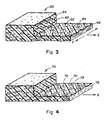
- Figure 3 illustrates a unitary reflective lens let support 60 which has been biaxially oriented [biaxially stretched, i.e., stretched in both the longitudinal (X) and transverse (Y) directions], as indicated by the arrows.
- the support 60 is illustrated in section, showing microbeads 62 contained within circular microvoids 64 in the polymeric continuous matrix 66.
- the microvoids 64 surrounding the microbeads 62 are theoretically regular in shape, but on microscopic examination often show irregularities, particularly when the random spacing of the microbeads results in two or more microbeads being located in close proximity.
- Figure 4 also illustrates a unitary reflective lenslet support 70 which has been unidirectionally oriented (stretched in one direction only, as indicated by the arrow).
- Microbeads 72 are contained between microvoid lobes 74 and 74′.
- the microvoid lobes in this instance form at opposite sides of the microbeads as the sheet is stretched.
- the stretching is done in only the longitudinal direction (X) as indicated by the arrow, the microvoids will form on the leading and trailing sides of the microbeads. This is because of the unidirectional orientation as opposed to the bidirectional orientation of the sheet shown in Figure 4. This is the only difference between the supports of Figures 3 and 4.
- Figures 5 and 6 are sectional views which illustrate on an enlarged scale a single reflective lenslet, microbead 80 being entrapped within the polymeric continuous matrix 82 and encircled by microvoid 84. This lenslet shape results from the support being stretched in both the X and Y directions.
- Figure 7 is a view similar to Figure 5, except illustrating in enlarged form microbead 90 entrapped in the polymeric continuous matrix 92, having formed on opposite sides thereof microvoid lobes 94 and 94′, which are formed when the support is stretched only in the direction of the arrow X.
- FIG 8 is an enlargement illustrating a specific manner in which microvoids can be formed in a polyester continuous matrix as the support is stretched or oriented.
- the formation of the microvoids 100 and 100′ around microbeads 102 is illustrated on a stretch ratio scale as the support is stretched up to 4 times its original dimension. For example, as the support is stretched 4 times its original dimension in the X direction (4X), the microvoids extend to the points 104 and 104′, respectively.
- Figures 9 and 10 are actual photomicrographs of sections of a reflective lens let support according to this invention which has been frozen and fractured. The continuous polymeric matrix, microbeads, and microvoids are obvious.
- Figure 11 is an actual photomicrograph of a section of support oriented in one direction. The scale of these photomicrographs is indicated at the top of each in micrometers ( ⁇ m).
- the reflective lenslet supports are comprised of a continuous thermoplastic polyester phase having dispersed therein microbeads of cellulose ester which are at least partially bordered by voids.
- the supports are conveniently in the form of sheets or film.
- the polyester is relatively strong and tough, while the cellulose acetate is relatively hard and brittle.
- the present invention provides supports comprising a continuous thermoplastic polyester phase having dispersed therein microbeads of cellulose ester which are at least partially bordered by voids, the microbeads of cellulose acetate being present in an amount of 10-30% by weight based on the weight of polyester, the voids occupying 2-50% by volume of the shaped article, the composition of the shaped article when consisting only of the polyester continuous phase and microbeads of cellulose ester bordered by voids characterized by having a Kubelka-Munk R value (infinite thickness) of 0.90 to 1.0 and the following Kubelka-Munk values when formed into a 3 mil (76.2 microns) thick film: Opacity - about 0.78 to about 1.0 SX - 25 or less KX - about 0.001 to 0.2 Ti - about 0.02 to 1.0 wherein the opacity values indicate that the article is opaque, the SX values indicate a large amount of light scattering through the thickness of the
- the Kubelka-Munk values which are dependent on thickness of the article must be specified at a certain thickness.
- the supports themselves may be very thin, e.g., less than 1 mil (25.4 micron) or they may be thicker, e.g., 20 mils (508 microns)
- the Kubelka-Munk values, except for R( ⁇ ) are specified at 3 mils (76.2 microns) and in the absence of any additives which would effect optical properties.
- the polyester containing microbeads at least partially bordered by voids, without additives should be formed in a 3 mils (approx. 75 ⁇ m) thick film for determination of Kubelka-Munk values.
- the supports according to this invention are useful, for example, when in the forms of sheets or films. In the absence of additives or colorants, they are very white.
- the supports are very resistant to wear, moisture, oil, tearing, etc.
- the polyester (or copolyester) phase may be any article-forming polyester such as a polyester capable of being cast into a film or sheet, spun into fibers, extruded into rods or extrusion, blow-molded into containers such as bottles, etc.
- the polyesters should have a glass transition temperature between 50°C and 150°C, preferably 60-100°C, should be orientable, and have an I.V. of at least 0.55, preferably 0.6 to 0.9.
- Suitable polyesters include those produced from aromatic, aliphatic or cycloaliphatic dicarboxylic acids of 4-20 carbon atoms and aliphatic or alicyclic glycols having from 2-24 carbon atoms.
- suitable dicarboxylic acids include terephthalic, isophthalic, phthalic, naphthalene dicarboxylic acid, succinic, glutaric, adipic, azelaic, sebacic, fumaric, maleic, itaconic, 1,4-cyclohexanedicarboxylic, and mixtures thereof.
- suitable glycols include ethylene glycol, propylene glycol, butanediol, pentanediol, hexanediol, 1,4-cyclohexanedimethanol, diethylene glycol, and mixtures thereof.
- polyesters are well known in the art and may be produced by well-known techniques, e.g., those described in U.S. Patents 2,465,319 and 2,901,466.
- the preferred polyester is polyethylene terephthalate having a Tg of about 80°C.
- suitable polyesters include liquid crystal copolyesters formed by the inclusion of a suitable amount of a co-acid component such as stilbene dicarboxylic acid. Examples of such liquid crystal copolyesters are those disclosed in U.S. Patent Nos. 4,420,607, 4,459,402 and 4,468,510.
- Blends of polyesters and/or copolyesters are useful in the present invention. Also, small amounts of other polymers such as polyolefins can be tolerated in the continuous matrix.
- Suitable cellulose acetates are those having an acetyl content of 28 to 44.8% by weight, and a viscosity of 0.01-90 seconds. Such cellulose acetates are well known in the art. Small contents of propionyl can usually be tolerated. Also, processes for preparing such cellulose acetates are well known in the art.
- Suitable commercially available cellulose acetates include the following which are marketed by Eastman Chemical Products, Inc.: Cellulose Acetate Type Viscosity1 Acetyl Content %2 Hydroxyl Content %2 Melting Range °C Tg, °C Number Average Molecular Weight3 Seconds Poises (Pascal-Sec.) CA-394-60S 60.0 22.8 39.5 4.0 240-260 186 60,000 CA-398-3 3.0 1.14 39.8 3.5 230-250 180 30,000 CA-398-6 6.0 2.28 39.8 3.5 230-250 182 35,000 CA-398-10 10.0 3.80 39.8 3.5 230-250 185 40,000 CA-398-30 30.0 11.40 39.7 3.5 230-250 189 50,000 CA-320S 0.05 0.02 32.0 8.4 190-269 about 180-190 about 18,000 CA-436-80S 80 30.4 43.7 0.82 269-300 180 102,000 1ASTM D817 (Formula A) and D1343 2ASTM D8
- the microbeads of cellulose esters range in size from 0.1-50 microns, and are present in an amount of 10-30% by weight based on the weight of the polyester.
- the microbeads of cellulose acetate have a Tg of at least 20°C higher than the Tg of the polyester and are hard compared to the polyester.
- the microbeads of cellulose acetate are at least partially bordered by voids.
- the void space in the shaped article should occupy 2-50%, preferably 20-30%, by volume of the shaped article.
- the voids may completely encircle the microbeads, e.g., a void may be in the shape of a doughnut (or flattened doughnut) encircling a microbead, or the voids may only partially border the microbeads, e.g., a pair of voids may border a microbead on opposite sides.
- the invention does not require but permits the use or addition of a plurality of organic and inorganic materials such as fillers, pigments, anti-blocks, anti-stats, plasticizers, dyes, stabilizers, nucleating agents, etc. These materials may be incorporated into the matrix phases, into the dispersed phases, or may exist as separate dispersed phases.
- organic and inorganic materials such as fillers, pigments, anti-blocks, anti-stats, plasticizers, dyes, stabilizers, nucleating agents, etc.
- microvoids form on cooling without requiring nucleating agents.
- the voids assume characteristic shapes from the balanced biaxial orientation of paperlike films to the uniaxial orientation of microvoided/satin-like fibers.
- Balanced microvoids are largely circular in the plane of orientation while fiber microvoids are elongated in the direction of the fiber axis.
- the size of the microvoids and the ultimate physical properties depend upon the degree and balance of the orientation, temperature and rate of stretching, crystallization kinetics, the size distribution of the microbeads, and the like.
- the supports according to this invention are prepared by
- the mixture may be formed by forming a melt of the polyester and mixing therein the cellulose acetate.
- the cellulose acetate may be in the form of solid or semi-solid microbeads, or in molten form. Due to the incompatability between the polyester and cellulose acetate, there is no attraction or adhesion between them, allowing the cellulose acetate to "bead-up" if molten to form dispersed microbeads upon mixing. If solid or semi-solid, the microbeads become uniformly dispersed in the polyester upon mixing.
- a shaped article is formed by processes such as extrusion, casting or molding. Examples of extrusion or casting would be extruding or casting a film or sheet. Such forming methods are well known in the art. If sheets or film material are cast or extruded, it is important that such article be oriented by stretching, at least in one direction. Methods of unilaterally or bilaterally orienting sheet or film material are well known in the art. Basically, such methods comprise stretching the sheet or film at least in the machine or longitudinal direction after it is cast or extruded by an amount of about 1.5-10 (usually 3-4) times its original dimension.
- Such sheet or film may also be stretched in the transverse or cross-machine direction by apparatus and methods well known in the art, in amounts of generally 1.5-10 (usually 3-4) times the original dimension.
- apparatus and methods are well known in the art ⁇ e.g., they are described in such U.S. Patent Nos. 3,903,234.
- the voids, or void spaces, referred to herein surrounding the microbeads are formed as the polyester continuous matrix is stretched at a temperature between the polyester Tg and the cellulose acetate Tg.
- the microbeads of cellulose acetate are relatively hard compared to the polyester continuous matrix.
- the polyester continuous matrix slides over the microbeads as it is stretched, causing voids to be formed at the sides in the direction or directions of stretch, which voids elongate as the polyester matrix continues to be stretched.
- the final size and shape of the voids depends on the direction(s) and amount of stretching.
- stretching is only in one direction, microvoids will form at the sides of the microbeads in the direction of stretching. If stretching is in two directions (bidirectional stretching), in effect such stretching has vector components extending radially from any given position to result in a doughnut-shaped void surrounding each microbead.
- the preferred preform stretching operation simultaneously opens the microvoids and orients the matrix material.
- the final product properties depend on and can be controlled by stretching time-temperature relationships and on the type and degree of stretch. For maximum opacity and texture, the stretching is done just above the glass transition temperature of the matrix material. When stretching is done in the neighborhood of the higher glass transition temperature, both phases stretch together and opacity decreases. In the former case, the materials are pulled apart, a mechanical anti-compatibilization process. In the latter case, they are drawn together, a mechanical compatibilization process. Two examples are high-speed melt spinning of fibers and melt blowing of fibers and films to form non-woven/spun-bonded products. In summary, the scope of this invention includes the complete range of forming operations just described.
- void formation occurs independent of, and does not require, crystalline orientation of the matrix phase.
- Opaque, microvoided films have been made in accordance with the methods of this invention using completely amorphous, non-crystallizing copolyesters as the matrix phase.
- Crystallizable/orientable (strain hardening) matrix materials are preferred for some properties like tensile strength and barrier effectiveness.
- amorphous matrix materials have special utility in other areas like tear resistance and heat sealability.
- the specific matrix composition can be tailored to meet many product needs. The complete range from crystalline to amorphous matrix materials is part of the invention.
- the specified materials were combined and mixed in A dry state prior to extrusion.
- Most of the materials used in these examples are granules (ground through a 2 millimeter screen) and fine powders. This form permits good dry blending without separation during processing.
- the mixed materials were dried under vacuum conditions with nitrogen bleed to carry off the volatiles.
- the relative amounts of the polyester, cellulose ester, and other materials are indicated by mass ratios; and all percents are weight %.
- the materials are melted and mixed as viscous melts.
- Shear emulsification of the immiscible melts was enhanced with a mixing section centrally located in the metering section of the extruder screw. Residence time was kept small by design; for example, screw L/D was 24:1 [Killion 1.25 inch (31.8 mm) extruder] and the dies were joined directly to the extruder via small-sized adaptors The extrudate is quenched to form flat films or sheet. The required orientation was carried out by conventional equipment and methods associated with the specific forming operation.
- Blends were prepared with a polyester and a cellulose acetate.
- the polyester is Polyester A (described below) and the cellulose ester is cellulose acetate CA-398-30.
- Two blends (80/20) and (90/10) were melt cast to form sheets between 15 to 20 mils (381 to 508 microns) thick. These sheets were simultaneously stretched 4X (a multiple of 4) in both directions to form white, paper-like films just over 1 mil (25.4 microns) thick.
- the films of this invention are highly diffuse reflective over the visible spectrum and remain highly reflective in the near UV (300 to 400 nanometer wavelengths) region. Typical films properties and processing conditions are given below.
- Example 2 This example is an example of prior art. It is given here for direct comparison with Example 1. Blends were prepared with the same polyester as Example 1 and inorganic materials. The inorganics are titanium dioxide (Rutile R-100) and calcium carbonate (Microwhite 25). A (90/10) blend of the polyester and each of the inorganics was melt cast to form sheets between 15 to 20 mils (381 to 508 microns) thick. These sheets were simultaneously stretched 4X in both directions to form white, plastic-like films just over 1 mil (25.4 microns) thick. Typical film properties and processing conditions are given below.
- Blends were prepared with a polyester and a cellulose acetate.
- the polyester is a blend of Polyester A and Polyester A containing a covalently bound colorant.
- the cellulose acetate is CA-398-30.
- Two (80/20) blends (one containing 0.5% red moiety and one containing 0.5% blue moiety) were melt cast to form sheets 20 mils (508 microns) thick. These sheets were simultaneously stretched 4X in both directions to form pastel-colored, paper-like films about 1.75 mils (44.5 microns) thick. Typical film properties and processing conditions are given below.
- Blends were prepared with a polyester and a mixed cellulose ester, cellulose acetate propionate.
- the polyester is Polyester A and the cellulose ester is CAP-482-20.
- This (90/10) blend and a (90/10) blend made like Example 1 were melt cast to form sheets 15 mils (381 microns) thick. These sheets were simultaneously stretched 4X in both directions to form translucent, paper-like films about 1 mil (25.4 microns) thick. Typical film properties and processing conditions are given below.
- Blends were prepared with the same polyester and cellulose acetate as Example 1.
- the specific blends (95/5), (90/10), (85/15), (80/20), (75/25), and (70/30) were melt cast to form sheets 25 mils (635 microns) thick.
- Extrusion conditions were similar to those of Example 1. These sheets were simultaneously stretched 3X in both directions to form white, paper-like films 3 mils (76.2 microns) thick. These sheets were also simultaneously stretched 4X in both directions to form white, paper-like films 2 mils (50.8 microns) thick. Typical film optical properties are given below.
- Example 2 shows that light-colored, opaque structures developed when the dispersed phase was colored.
- the polyester of Example 1 was mixed with a cellulose acetate (CA-320S, containing a covalently bonded colorant).
- a (90/10) blend (containing 0.13% red moiety) was melt cast to form sheets 15 mils (381 microns) thick. These sheets were stretched as in Example 1 yielding uniformly pastel-red, opaque, paper-like films.
- a blend was prepared with a polyester and a cellulose acetate.
- the polyester is Polyester B (described below) and the cellulose acetate is CA-398-30.
- a (90/10) blend was melt cast to form sheets between 15 to 20 mils (381 to 508 microns) thick.
- a Brabender 3/4-inch (19-mm) laboratory extruder without a mixing screw was used at 110 RPM and 260°C (melt temperature). These sheets were simultaneously stretched 4X in both directions to form white, paper-like films just over 1 mil (25.4 microns) thick. These films contained visible particles of cellulose acetate resulting from the incomplete shear emulsification on this machine.
- Example 2 shows that white, opaque properties developed over a range of stretching conditions.
- a (90/10) blend of the same materials as Example 1 was melt cast using the equipment of Example 6. Stretching conditions were (2x1), (2x2), (3x1), (3x2), (3x3), (4x1), (4x2), (4x3) and (4x4). Whiteness and opacity were visually evident at all levels of stretching, increasing with balance and degree of stretch.
- polyester/polyester blends can be used with cellulose acetates to produce articles of this invention.
- the specific blends of this example are (65/25/10) and (65/15/20) using Polyester A, Polyester C, and CA-398-30 respectively. Films were made as in Example 1, and the resulting properties were similar. The films of this example, however, were more flexible due to the presence of the thermoplastic elastomer in the blend.
- Blends were prepared with a polyester and a cellulose acetate.
- the polyester is Polyester A and the cellulose acetate is CA-394-60S.
- the following blends (95/5), (90/10), (85/15), and (80/20) were melt extruded and simultaneously biaxially oriented on a laboratory blown film line.
- the oriented tubes had a layflat width of 9 to 12 inches (22.9 to 30.5 centimeters), and the film thickness was about 0.5 mil (12.7 microns). These films were white, opaque, and had tissue paper qualities. Typical film properties and processing conditions are given below.
- Blends were prepared with a polyester and a cellulose acetate.
- the polyester is a blend of Polyester A and Polyester A containing a covalently bound colorant.
- the cellulose acetate is CA-398-30.
- Four (80/20) blends were melt extruded and simultaneously biaxially oriented as in Example 10. Typical film properties and processing conditions are given below.
- a (90/10) blend was prepared with a higher glass transition polyester, Polyester D, and a cellulose acetate (CA-394-60S). This blend was melt extruded at a melt temperature of 270°C and simultaneously biaxially oriented at about 140°C as in Example 10. The resulting film was white, opaque, and paper-like. This blend system is especially attractive if high temperature resistant products are being manufactured.
- the blends of this example were prepared from a polyester, a polypropylene, and a cellulose acetate.
- the polyester is Polyester A; the polypropylene homopolymer is PP 4230; and the cellulose acetate is CA-394-60S.
- Three blends (70/10/20), (75/5/20), and (77/3/20) were melt extruded and simultaneously biaxially oriented as in Example 10. White, opaque, paper-like films were made, however film strength and quality decreased as the level of polypropylene increased.
- a (90/10) blend was prepared with a polyester, Polyester A, and a cellulose triacetate CA-436-80S. This blend was melt extruded at a melt temperature of 275°C and simultaneously biaxially oriented as in Example 10. White, opaque, paper-like films were made, however the quality of the film was degraded by the presence of small particles of incompletely melted cellulose triacetate.
- Blends were prepared with a polyester, Polyester A, a water-dispersible polyester, and a cellulose acetate (CA-398-30).
- the blend was melt extruded and simultaneously biaxially oriented as in Example 10.
- the white, opaque, paper-like films were of good quality, with an enhanced hydrophilic character due to the presence of the hydrophilic polyester.
- a (90/10) blend of an amorphous copolyester and a cellulose acetate was prepared.
- the copolyester was Polyester E, and the cellulose acetate was CA-394-60S.
- the blend was melt extruded and simultaneously biaxially oriented as in Example 10; however the white, opaque, paper-like films had a faint, yellowish tint, indicating greater thermal degradation.
- a (90/10) blend of another copolyester and a cellulose acetate was prepared.
- the copolyester was Polyester F and the cellulose acetate was CA-398-30.
- the blend was melt extruded and simultaneously biaxially oriented as in Example 10. A good quality, white, opaque, paper-like film resulted.
- a (90/10) blend was prepared from a polyester, Polyester A, and a lower viscosity cellulose acetate (CA-398-3).
- a second (90/10) blend of this polyester with a lower percent acetyl cellulose acetate (CA-320S) was also prepared. Both blends were melt extruded and simultaneously biaxially oriented as in Example 10. Good quality, white, opaque, paper-like films resulted.
- Polyester E is described as follows: Reaction Product Of: Dicarboxylic acid(s) or Ester Thereof terephthalic acid Glycol(s) 69 mol % ethylene glycol 31 mol % 1,4-cyclohexanedimethanol I.V. 0.75 Tg 80°C Tm amorphous
- Polyester F is described as follows: Reaction Product Of: Dicarboxylic acid(s) or Ester Thereof 75 mol % terephthalic acid 25 mol % trans-4,4′-stilbene dicarboxylic acid Glycol(s) ethylene glycol I.V. 0.8 Tg 95°C Tm 215°C
- CA cellulose acetates
- ratios or parts are given, e.g., 80/20, they are parts by weight, with the polyester weight specified first.
- Ro, R and Rg are determined in a conventional manner using a Diano Match-Scan II Spectrophotometer (Milton Roy Co.) using a wavelength of 560 nanometers.
- X in the formulae SX and KX is the thickness of the article. A full description of these terms is found in "Business, Science and Industry” 3rd Edition, by Deane B. Judd & Gunter Wyszecki, published by John Wiley & Sons, N.Y. (1975), pages 397-439.
- Glass transition temperatures, Tg, and melt temperatures, Tm are determined using a Perkin-Elmer DSC-2 Differential Scanning Calorimeter.
- ester forming derivatives of the acids may be used rather than the acids themselves as is conventional practice.
- dimethyl isophthalate may be used rather than isophthalic acid.
- oxygen permeability is determined according to ASTM D 3985, in cubic centimeters permeating a 1 mil (25.4 ⁇ m) thick sample, 100 inches square (approx. 64,500 cm2), for a 24-hour period under oxygen partial pressure difference of one atmosphere at 30°C. using a MOCON Oxtran 10-50 instrument. Oxygen permeability is also given in S.I. (Systems International) units in cubic centimeters permeating a 1 cm. thick sample, 1 cm. square, for 1 second at atmospheric pressure.
- Reflective lenslet supports for the intensifying screens of this invention can also be formed from extruded or cast articles, such as sheets or film, that contain closed microcells and are tentered to flatten and thereby orient the microcells with major axes extending in the directions of tentering, similarly as the stretch cavitation microvoided supports described above.
- the support is comprised of polymeric continuous phase or matrix, which can be identical to that of the stretch cavitation microvoided supports described above.
- the support need contain no microbeads. Instead the support contains a blowing agent ⁇ that is, an agent capable of generating a dispersed entrapped gas phase (microcells) in the continuous phase during or immediately following extrusion or casting.
- the entrapped dispersed gas phase forms spherical voids in the support. Tentering the support flattens the voids to the flattened spheroidal shape required for reflection of emitted radiation.
- the pressure exerted by the entrapped gas prevents collapse of the lenslets and obviates any necessity of incorporating microbeads, either for the generation or maintenance of the lenslets.
- the voids in the support have a lower index of refraction than the surrounding continuous phase, they are not useful as reflection lenslets in their initially formed spherical form. Rather, in this instance, when the dispersed gas phase forms spherical microcells (bubbles), the emitted radiation will be scattered and no lens action contributing to increased sharpness occurs.
- the lenslets themselves have a low refractive index of approximately 1.0, typical of vacuum and gases, while the surrounding continuous phase has a higher refractive index typical of polymeric materials.
- Most common organic polymers exhibit refractive indices in the range from about 1.4 to 1.6.
- the mismatch between the refractive index of the continuous polymer phase or matrix and the microvoid or entrapped gas bubble (microcell) is essential to the function of a lenslet.
- the discrete, dispersed phase must have a lower refractive index that the surrounding continuous phase for lens effects to be obtained.
- the discrete dispersed phase can take the form of any convenient material transparent to emitted radiation. It is preferred that the dispersed phase also be substantially transparent to X-radiation, but this is not essential when the intensifying screen is to be employed as a back screen.
- the material or microvoid forming the lenslets described above can be replaced by microbeads having the noted transparency and a refractive index at least 0.2, preferably at least 0.5, higher than that of the surrounding continuous phase.
- microbeads having refractive indices in the range of from about 1.5 to 2.5 or higher can be conveniently dispersed in the continuous polymeric phase to form the reflective lenslet support.
- the higher refractive index microbeads can be spherical. In this instance no orientation of the microbeads is possible or required. Instead of forming the microbeads of spherical form, they can be spheroidal-e.g., similar in shape to either the microvoids or bubbles employed as a dispersed phase described above. Biaxial tentering of the support can be relied upon to align nonspherical microbeads with their major axes parallel to a major surface of the support (and hence the fluorescent layer) just as described above to align the lower index of refraction dispersed phase lenslets.
- a significant advantage of employing spherical microbeads is that no tentering of the support is required.
- the use of spherical microbeads is well suited to casting the microbeads in the continuous polymeric phase on a previously formed substrate portion of the support.
- the spheres require no special alignment step or, viewed another way, the spheres are always properly aligned to act as light reflecting lenslets.
- a distinct advantage of employing a higher index of refraction discrete phase to form the lenslets is that such materials can be relied upon to enhance the physical strength of the support. Consequently, both the occurrence frequency and size restrictions that must be observed to preserve the physical integrity of a support relying on microvoids or microcells for lens let fabrication are not relevant. Rather, it is specifically contemplated that the microbeads can be employed up to their maximum packing density consistent with retaining a continuous surrounding continuous phase. For spherical and spheriodal microbeads the geometrical relationship of the microbeads allows a surrounding continuous phase to be maintained even when the microbeads are contiguously packed.
- microbeads for lenslet construction that exceed the thickness of the surrounding continuous polymeric phase or matrix.
- Cast reflective lenslet support layer portions are specifically contemplated to contain microbeads that extend up to 50 percent, preferably up to about 20 percent, above the surface of the surrounding polymeric matrix to enhance adhesion of the fluorescent layer to the support.
- the longest dimension of the microbeads should be less than, preferably less than 50 percent, that of the overall thickness of the support.
- microbeads of a size larger than the lower index of refraction lenslets for the reasons noted above, for the highest achievable point to point uniformity in imaging it is generally preferred that the microbeads be restricted to the micrometer size ranges described above in connection with the microvoids and microbeads employed for producing stretch cavitation microvoided supports.
- microbeads are described above as being spherical or spheroidal, it is appreciated that many regular and irregular polyhedral particles, such as those produced by crystallization, approximate spherical or spheroidal shapes.
- a sphere can be viewed as the limiting example of a regular polyhedron having an indeterminate number of faces. Even without rounding of apices dodecahdra and higher faceted polyhedra appear roughly spherical. In practical crystallography, microcrystals often exhibit sufficient rounding of apices with as few as eight faces as to be essentially spherical. In many respects even lower faceted polyhedra, such as tetrahedra, exhibit reflection geometries conducive to lens activity. On the other hand, randomly oriented cubic crystals with distinct facets are not suitable for use as reflective lenslets.
- a planar specularly reflective surface a Lambertion surface
- the angle of reflection equals the angle of incidence.
- Fig. 12 wherein the reflective surface 110 receives electromagnetic radiation, indicated by arrow 112, at an angle ⁇ 1 measured with respect to an axis 114 normal to the surface, commonly referred to as the surface normal.
- the angle ⁇ 1 is the angle of incidence.
- the electromagnetic radiation reflected from the surface, indicated by arrow 116, is oriented at an angle ⁇ 2 with respect the surface normal, referred to as the angle of reflection, which equals the angle of incidence.
- the term "lenslet” is defined as a discrete phase (including a microvoid) contained in the continuous polymeric phase of the support which is capable of reducing the angle of reflection ( ⁇ 2) in relation to the angle of incidence ( ⁇ 1) of emitted longer wavelength electromagnetic radiation received from the fluorescent layer of the intensifying screen. From the foregoing definition it is apparent that the lenslets are in fact lenses. The term “lenslet” rather than “lens” is, however, employed simply to emphasize the limited extent of the major axes of the lenslets in relation to the overall length and breadth of the support.
- the minor axis (the axis normal to the fluorescent layer) of a lenslet is less than the thickness of the support, and the ratio of major to minor axes of the lenslets range from about 1:1 (as in the case of a spherical lenslet) to 10:1 (but usually 5:1 or less).
- Preferred lenslets are those which not only reduce the angle of reflection, but actually exhibit a negative angle of reflection, - ⁇ 2. This is illustrated schematically in Fig. 13, wherein 110, 112, and 114 illustrate features identical to those of Fig. 12. The sole difference is that the reflected electromagnetic radiation, indicated by the arrow 116′ is now oriented between the incident radiation and the surface normal, giving the angle of reflection a negative value, indicated as - ⁇ 2.
- the optimum lenslet construction permitting the highest attainable sharpness in the intensifying screens of this invention, is achieved when the lenslets are retroreflective ⁇ that is, capable of directing reflected radiation back toward the fluorescent layer along an axis parallel to the axis of incidence.
- FIG. 14 A white pigment sphere 120 is shown. Longer wavelength electromagnetic radiation which strikes the sphere along an axis which is aligned with a diameter of the sphere (a diametrical axis), indicated by arrow 122, is mostly retroreflected, as indicated by arrow 124, with a small part being absorbed, as indicated by dashed arrow 126.
- white pigments conventionally employed for support construction such as titania and barium sulfate, though they appear white, actually absorb radiation over at least a portion of the electromagnetic spectrum.
- titania exhibits a significant increase in absorption of electromagnetic radiation in moving from the 500 nm (green) region of the spectrum to the 400 nm (blue) and 350 nm (near ultraviolet) regions of the spectrum.
- Pigments that are commonly referred to as white pigments are in fact not entirely reflective.
- Fig. 14 a single, spherical white pigment particle is shown.
- the particles are grains rather than regular spheres, but the optical scattering by the grains is roughly similar.
- grains are closely packed in a coating or substrate. This results in a higher degree of scattering of electromagnetic radiation back toward the fluorescent layer than is achieved by isolated spheres.
- the overall effect is of predominant scattering of incident radiation accompanied by significant absorption, particularly in the blue and near infrared portions of the spectrum.
- the support forming the intensifying screen is comprised of transparent spheres as a dispersed phase in a transparent continuous polymeric phase.
- the spheres to function as lenslets, it is necessary that the spheres have a higher index of refraction than the surrounding continuous phase.
- An ideal relationship is shown in Fig. 15, wherein a sphere 140 is shown chosen so that the ratio of its refractive index to that of the surrounding continuous phase, not shown, is exactly two.
- Longer wavelength electromagnetic radiation striking the sphere, indicated by arrow 142 enters the sphere and is reflected from the sphere, indicated by arrow 144, along an axis that is parallel to the axis of incident radiation. With this relationship of refractive indices the sphere is retroreflective. The longer wavelength electromagnetic radiation reaching the sphere is neither absorbed nor scattered.
- the lateral offset of incident and retroreflected radiation is negligibly small. However, even this small offset can be reduced or eliminated.
- the reflected radiation can actually converge on the axis of incident radiation. In other words, a focused reflection of longer wavelength electromagnetic radiation is possible.
- the difference in the refractive indices are less than two, some divergence of the axis of the reflected radiation relative to that of the incident radiation occurs.
- a preferred useful range of ratios of the higher refractive index of the sphere and the lesser refractive index of the surrounding continuous polymeric phase is from 1.7 (preferably 1.9) to 2.1.
- the spherical lenslets are capable of retroreflection or a close approximation thereof, as described above, regardless of the angle of emission of the longer wavelength electromagnetic radiation from the fluorescent layer. Since fluorescent layers are commonly constructed as turbid layers to inhibit internal lateral scattering of emitted radiation, a large percentage of the longer wavelength electromagnetic radiation striking the spherical lenslets in the support is emitted along axes that are not normal to the fluorescent layer.
- the transparent sphere 140 shown in Fig. 15 it is not possible to substitute for the transparent sphere 140 shown in Fig. 15 an identical transparent sphere (including a spherical microvoid) differing only in that its refractive index is less than that of the surrounding continuous polymeric phase. When this change is made, the sphere becomes a diffuse reflector and its lenslet properties are lost.
- the sphere having a lower refractive index than that of the surrounding continuous polymeric phase is replaced by a spheroid (or microvoid) of the same refractive index and having major axes parallel to the fluorescent layer and having a ratio of major axes to its normal minor axis of at least 1.5:1 (preferably at least 3:1), then lenslet properties are exhibited.
- microbead When the microbead is a white pigment particle, it functions like a diffuse reflector; however, because it is nearly entirely surrounded by a microvoid, the scattering effects of the pigment particle are more than offset by the lenslet capability of the microvoid.
- microbeads for incorporation in microvoids is a transparent sphere or a transparent particle.
- the surrounding microvoid and the transparent microbead work together as lenslets, each making a significant contribution toward reduction of scattering of longer wavelength electromagnetic radiation.
- any conventional intensifying screen containing a reflective support can be realized by substituting a reflective lenslet support as described above. It is therefore apparent that the fluorescent layer can take the form of any conventional fluorescent layer heretofore employed in an intensifying screen in combination with a reflective support. What is surprising is that the reflective lenslet supports, particularly the retroreflective supports, can beneficially replace the support in any conventional intensifying screen, including conventional screens with absorbing and transparent supports.
- any conventional fluorescent layer can be employed in the intensifying screens of this invention, it is preferred to improve further the speed and sharpness characteristics of these intensifying screens by choosing fluorescent layers that satisfy a selected combination of requirements.
- retroreflective supports such as any of variations described above in connection with Fig. 15, are employed, image definitions can be realized equalling those of conventional intensifying screens employing black and transparent supports while significantly exceeding their maximum attainable speeds.
- the first and most fundamental of preferred fluorescent layer features is that the layer have the capability of absorbing sufficient X-radiation, sometimes referred as "high X-radiation absorption cross-section". This requirement can be objectively measured.
- the preferred fluorescent layers are capable of attenuating greater than 5 percent (preferably at least 10 percent) of a reference X-radiation exposure produced by a Mo target tube operated at 28 kVp with a three phase power supply, wherein the reference X-radiation exposure passes through 0.03 mm of Mo and 4.5 cm of poly(methyl methacrylate) to reach said fluorescent layer mounted 25 cm from a Mo anode of the target tube and attenuation is measured 50 cm beyond the fluorescent layer.
- the fluorescent layer X-radiation absorption capability be as high as possible, taking other competing considerations, such as image sharpness and optical density into account.
- Higher X-radiation absorption efficiencies for a given phosphor coating coverage can be realized by choosing phosphors containing higher atomic number elements, such as elements in Period 6 of the Periodic Table of Elements. Since Periodic Table designations vary, particularly in element Group designations, this description conforms to the Periodic Table of Elements adopted by the American Chemical Society.
- Calcium tungstate intensifying screens are generally accepted as the industry standard for conversion efficiency measurements.
- Preferred phosphors are those having a conversion efficiency at least equal to that of calcium tungstate.
- Specifically preferred phosphors are those exhibiting conversion efficiencies at least 1.5 times greater than the conversion efficiency of calcium tungstate, such as rare earth activated lanthanum oxybromides, yttrium tantalates, and gadolinium oxysulfides.
- MTF modulation transfer factor
- the MTF profile of the fluorescent layer is preferably in all instances equal to or greater than the modulation transfer factors of Curve B in Figure 16.
- Preferred fluorescent layers are those having MTF's at least 1.1 times those of reference curve B over the range of from 5 to 10 cycles per mm.
- Modulation transfer factor (MTF) measurement for screen-film radiographic systems is described by Kunio Doi et al, "MTF and Wiener Spectra of Radiographic Screen-Film Systems", U.S. Department of Health and Human Services, pamphlet FDA 82-8187.
- the profile of the individual modulation transfer factors over a range of cycles per mm is also referred to as a modulation transfer function.
- a more stringent MTF profile is represented by Curve A of Fig. 16.
- Intensifying screens satisfying this more stringent MTF profile were disclosed for the first time by Luckey, Roth, et al U.S. Patent 4,710,637 to be employed as front screens in an assembly of the type shown in Fig. 2.
- This patent clearly recommends the selection of transparent or black supports for front intensifying screens satisfying the MTF profile of Curve A.
- the reflective lenslet supports, particularly the retroreflective supports make possible intensifying screens satisfying MTF profile Curve A exhibiting higher imaging speeds.
- the invention particularly improves on the front screens of Luckey, Roth, et al in permitting higher speeds to be realized while the fluorescent layer attenuates only 20 to 60 percent of the reference X-radiation exposure discussed above in connection X-radiation absorption.
- the sharpness of a thicker fluorescent layer can be tailored to match that of a thinner fluorescent layer by adding a substance, such as a dye or pigment, capable of absorbing a portion of the longer wavelength electromagnetic radiation emitted by the phosphor layer.
- a substance such as a dye or pigment
- Emitted radiation traveling in the fluorescent layer to the extent it departs from a direction normal to the fluorescent layer major faces, experiences an increased path length in the fluorescent layer that increases its probability of absorption This renders the emitted radiation which would contribute disproportionately to sharpness degradation more likely to be absorbed in the fluorescent layer, provided a light absorbing material is present. Even very small amounts of absorbing material are highly effective in improving sharpness.
- fluorescent layers are sometimes fabricated with combinations of longer wavelength electromagnetic radiation absorbing and scattering materials, such as combinations of carbon and titania, to adjust screen performance to a selected aim.
- Conventional practices of incorporating longer wavelength electromagnetic radiation absorbing and scattering materials, such as dyes, reflective pigments, carbon, etc., are fully compatible with the reflective lenslet supports.
- the preferred fluorescent layers of this invention rely entirely or at least primarily on the reflective lenslet support rather than incorporated white pigments in the fluorescent layer for reflection of emitted radiation.
- the incorporation of a material capable of absorbing emitted radiation in the fluorescent layer reduces its effective thickness as compared to its actual thickness.
- the effective thickness of a fluorescent layer is herein defined as the thickness of an otherwise corresponding reference fluorescent layer having the same modulation transfer factors and consisting essentially of the phosphor and its binder in the same proportions on a support having a total reflectance of less than 20 percent.
- the preferred fluorescent layers of the intensifying screens of this invention exhibit an optical density to emitted radiation of less than 1.0.
- the fluorescent layer optimally exhibits an optical density of less than 0.5.
- the importance of minimizing the optical density of the fluorescent layer to emitted radiation is that the emitted radiation reflected by the support must penetrate the full thickness of the fluorescent layer to reach the radiographic element and thereby contribute to enhancing imaging speed.
- Both the objective of contributing to image sharpness and that of maintaining a preferred low optical density can be achieved when less than 0.1 percent, most preferably less than 0.006 percent, based on the weight of the phosphor, of a material capable of absorbing emitted radiation is present in the fluorescent layer.
- Phosphors of one preferred class are niobium and/or rare earth activated yttrium, lutetium, and gadolinium tantalates.
- niobium-activated or thulium-activated yttrium tantalate has a conversion efficiency greater than 1.5 times that of calcium tungstate.
- Phosphors of another preferred class are rare earth activated rare earth oxychalcogenides and oxyhalides.
- employed rare earths are elements having an atomic number of 39 or 57 through 71.
- the rare earth oxychalcogenide and oxyhalide phosphors are preferably chosen from among those of the formula: M (w-n) M′ n O w X wherein: M is at least one of the metals yttrium, lanthanum, gadolinium, or lutetium, M′ is at least one of the rare earth metals, preferably cerium, dysprosium, erbium, europium, holmium, neodymium, praseodymium, samarium, terbium, thulium, or ytterbium, X is a middle chalcogen (S, Se, or Te) or halogen, n is 0.0002 to 0.2, and w is 1 when X is halogen or 2 when X
- Phosphors of an additional class are the rare earth activated rare earth oxide phosphors.
- terbium-activated or thulium-activated gadolinium oxide has a conversion efficiency greater than 2 times that of calcium tungstate.
- rare earth activated phosphors which do not employ a rare earth host are rare earth activated mixed alkaline earth metal sulfate phosphors.
- rare earth activated mixed alkaline earth metal sulfate phosphors For example, europium-activated barium strontium sulfate in which barium is present in the range of from about 10 to 90 mole percent, based on the total cation content of the phosphor, and europium is present in a range of from about 0.16 to about 1.4 mole percent, on the same basis, exhibits a conversion efficiency at least equal that of calcium tungstate.
- calcium tungstate is an example of a phosphor which satisfies the conversion efficiency requirement and contains no rare earth.
- Lead-activated barium sulfate, strontium sulfate, and barium strontium sulfate as well as lead sulfate phosphors are also known.
- Calcium tungstate phosphors are illustrated by Wynd et al U.S. Patent 2,303,942.
- Lead-activated barium sulfate phosphors are disclosed by Staudenmeyer U.S. Patent 3,617,285.
- Rare earth activated mixed alkaline earth phosphors are illustrated by Luckey U.S. Patents 3,650,976 and 3,778,615 and Schuil U.S. Patent 3,764,554.
- Rare earth-activated rare earth oxide phosphors are illustrated by Luckey U.S. Patent 4,032,471.
- Niobium-activated and rare earth-activated yttrium, lutetium, and gadolinium tantalates are illustrated by Brixner U.S. Patent 4,225,653.
- Rare earth-activated gadolinium and yttrium middle chalcogen phosphors are illustrated by Royce U.S. Patent 3,418,246.
- Rare earth-activated lanthanum and lutetium middle chalcogen phosphors are illustrated by Yocom U.S. Patent 3,418,247.
- Terbium-activated lanthanum, gadolinium, and lutetium oxysulfide phosphors are illustrated by Buchanan et al U.S. Patent 3,725,704.
- Cerium-activated lanthanum oxychloride phosphors are disclosed by Swindells U.S. Patent 2,729,604.
- Terbium-activated and optionally cerium-activated lanthanum and gadolinium oxyhalide phosphors are disclosed by Rabatin U.S. Patent 3,617,743 and Ferri et al U.S. Patent 3,974,389.
- Rare earth-activated rare earth oxyhalide phosphors are illustrated by Rabatin U.S. Patents 3,591,516 and 3,607,770.
- Terbium-activated and ytterbium-activated rare earth oxyhalide phosphors are disclosed by Rabatin U.S. Patent 3,666,676.
- Thulium-activated lanthanum oxychloride or oxybromide phosphors are illustrated by Rabatin U.S. Patent 3,795,814.
- a (Y,Gd)2O2S:Tb phosphor wherein the ratio of yttrium to gadolinium is between 93:7 and 97:3 is illustrated by Yale U.S. Patent 4,405,691.
- Non-rare earth coactivators can be employed, as illustrated by bismuth and ytterbium-activated lanthanum oxychloride phosphors disclosed in Luckey et al U.S. Patent 4,311,487. The mixing of phosphors as well as the coating of phosphors in separate layers of the same screen are specifically recognized.
- a phosphor mixture of calcium tungstate and yttrium tantalate is illustrated by Patten U.S. Patent 4,387,141.
- Phosphors can be used in the fluorescent layer in any conventional particle size range and distribution. It is generally appreciated that sharper images are realized with smaller mean particle sizes, but light emission efficiency declines with decreasing particle size. Thus, the optimum mean particle size for a given application is a reflection of the balance between imaging speed and image sharpness desired. Conventional phosphor particle size ranges and distributions are illustrated in the phosphor teachings cited above.
- the fluorescent layer contains sufficient binder to give structural coherence to the layer.
- the binders employed in the fluorescent layers of the unitary elements of this invention can be identical to those conventionally employed in fluorescent screens. Such binders are generally chosen from organic polymers which are transparent to X-radiation and emitted radiation, such as sodium o sulfobenzaldehyde acetal of poly(vinyl alcohol); chlorosulfonated poly(ethylene); a mixture of macromolecular bisphenol poly(carbonates) and copolymers comprising bisphenol carbonates and poly(alkylene oxides); aqueous ethanol soluble nylons; poly(alkyl acrylates and methacrylates) and copolymers of alkyl acrylates and methacrylates with acrylic and methacrylic acid; poly(vinyl butyral); and poly(urethane) elastomers.
- intensifying screen binders are poly(urethanes), such as those commercially available under the trademark Estane from Goodrich Chemical Co., the trademark Permuthane from the Permuthane Division of ICI, Ltd., and the trademark Cargill from Cargill, Inc.
- intensifying screens in combination with silver halide radiographic elements.
- intensifying screens and radiographic elements are separate items of commerce and are rarely sold together.
- the selection of radiographic elements selected is a matter of user choice.
- the radiographic elements that exhibit the lowest crossover produce the sharpest images.
- the highest attainable imaging speed and sharpness can be realized when low crossover tabular grain emulsion dual coated radiographic elements are employed in combination with the intensifying screens of this invention, such as those discloed by Abbott et al U.S. Patents 4,425,425 and 4,425,426.
- More recently tabular grain emulsion dual coated radiographic elements have been developed that exhibit less than 10 percent crossover and optimally less than 1 percent crossover employing a process bleachable filter dye in a layer interposed between each tabular grain emulsion layer and the radiographic element support.
- These radiographic elements commonly referred to as "zero crossover" radiographic elements, are disclosed in Dickerson et al U.S. Patent 4,803,150.
- Support A A stretch cavitation microvoided support, hereinafter referred to as Support A, was prepared similarly as that of Example 9 above.
- the support was formed of an overall composition of four components: poly(ethylene terephthalate), Polyester C, cellulose acetate microbeads, and a small amount of zinc oxide, which was added to stabilize the hot melt.
- the weight ratio of components was 73:18:9:0.14.
- the Polyester C component a thermoplastic elastomer, was a mixed polyester comprising 99.5 mole percent 1,4-cyclohexanedicarboxylic acid (esterification not determined), 0.5 mole percent of trimellitic anhydride, 91.9 mole percent of 1,4-cyclohexanedimethanol, and 8.9 mole percent of poly(tetramethylene ether glycol).
- the overall composition had an inherent viscosity of 1.23, a glass transition temperature below 0°C, and a melting point of 200°C.
- On the support was coated a 1.8 ⁇ m thick subbing layer of poly(vinyl alcohol).
- a control white pigment containing support, Support B was a poly(ethylene terephthalate) support containg 8 percent by weight rutile titania.
- Supports A and B were both sufficiently thick that further thickening would not produce a significant increase in reflectance.
- the reflectances of the supports as a function of wavelength are summarized in Table I.
- Table I Wavelength (nm) Reflectance (%) Support A Support B 360 64.1 8.2 380 71.0 13.5 400 79.7 43.5 450 83.8 84.0 500 84.7 86.5 600 85.6 87.1 700 86.5 86.2 Note that the reflectances of the supports were matched over the 700 to 450 nm portion of the spectrum. At shorter wavelengths the reflectance of the titania loaded support fell off sharply, following the known characteristic of white pigments of being incapable of reflecting efficiently in all spectral regions.
- a dispersion of europium-doped barium strontium sulfate phosphor with a mean particle size of approximately 5 ⁇ m was prepared from l00g of the phosphor in a solution prepared from 117g of polyurethane binder (trademark Permuthane U-6366) at 10 percent by weight in a 93:7 volume ratio of dichloromethane and methanol.
- the dispersion was coated at a phosphor coverage of 605g/m2 on Support A and 610g/m2 on Support B to produce the intensifying Screens A1 and B1, respectively.
- a pair of Screens A1 and a pair of Screens B1 were each placed in contact with a blue sensitive dual coated radiographic element commercially sold under the trademark Kodak X-Omat G film.
- the screen pair and radiographic arrangement for exposure like that shown in Fig. 2.
- the assemblies each containing a dual coated radiographic element between screen pairs were exposed through an aluminum step wedge, with a tungsten target tube operated with a single-phase power supply at 100 mA and 70 KVp, with no additional beam filtration and at a focal-film distance of 152.4 dm.
- the radiographic element/screen pair assemblies were exposed under the same conditions as above, exepct that in place of the step wedge, the X-ray beam was filtered with 0.5 mm of copper and 1 mm of aluminum, and the exposure passed through a "bone and beads" test object containing bone, plastic objects, steel wool, and miscellaneous objects having fine detail. Image sharpness was visually compared.
- control Screens B1 Taking the speed of the radiographic element exposed by the control Screens B1 as 100, the relative speed of the radiographic element exposed by invention Screens A1 was 148. The sharpness of the image produced by control Screens B1 was slightly higher than that produced by invention Screens A1.
- speed and sharpness are parameters that can be "traded off".
- the advantage can be realized entirely as a speed advantage, entirely as a sharpness advantage, or a combination of both.
- the large speed advantage with a small difference in sharpness demonstrated a significant improvement in the speed and sharpness relationship of the intensifying screens of this invention that can be realized entirely as a speed advantage or as a large sharpness advantage or an advantage apparent both in terms of speed and sharpness.
- Example 19 was repeated, except that a rare earth activated rare earth oxyhalide phosphor fluorescent layer was substituted.
- a dispersion was prepared employing a blue-emitting thulium-doped lanthanum oxybromide phosphor with a mean particle size of 5 ⁇ m in the amount of 100g and the same binder solution as employed in Example 20.
- the dispersion was coated at a phosphor coverage of 663g/m on Support A and 675g/m2 on Support B to give Screens 2A and 2B.
Landscapes
- Physics & Mathematics (AREA)
- General Physics & Mathematics (AREA)
- Engineering & Computer Science (AREA)
- General Engineering & Computer Science (AREA)
- High Energy & Nuclear Physics (AREA)
- Conversion Of X-Rays Into Visible Images (AREA)
- Silver Salt Photography Or Processing Solution Therefor (AREA)
Applications Claiming Priority (2)
| Application Number | Priority Date | Filing Date | Title |
|---|---|---|---|
| US243374 | 1988-09-12 | ||
| US07/243,374 US4912333A (en) | 1988-09-12 | 1988-09-12 | X-ray intensifying screen permitting an improved relationship of imaging speed to sharpness |
Publications (2)
| Publication Number | Publication Date |
|---|---|
| EP0360116A1 true EP0360116A1 (de) | 1990-03-28 |
| EP0360116B1 EP0360116B1 (de) | 1994-08-17 |
Family
ID=22918513
Family Applications (1)
| Application Number | Title | Priority Date | Filing Date |
|---|---|---|---|
| EP89116756A Expired - Lifetime EP0360116B1 (de) | 1988-09-12 | 1989-09-11 | Röntgen-Verstärkerschirm mit verbessertem Verhältnis von Bildempfindlichkeit zu Schärfe |
Country Status (5)
| Country | Link |
|---|---|
| US (1) | US4912333A (de) |
| EP (1) | EP0360116B1 (de) |
| JP (1) | JPH02186339A (de) |
| CA (1) | CA1313572C (de) |
| DE (1) | DE68917551T2 (de) |
Cited By (5)
| Publication number | Priority date | Publication date | Assignee | Title |
|---|---|---|---|---|
| EP0633497A1 (de) * | 1993-07-08 | 1995-01-11 | Agfa-Gevaert N.V. | Medizinisches Röntgenaufnahmesystem |
| EP1271559A2 (de) * | 2001-06-18 | 2003-01-02 | Eastman Kodak Company | Radiographischer Leuchtstoffträger mit polymerischem Mehrschicht-Reflektor |
| EP1316971A2 (de) * | 2001-12-03 | 2003-06-04 | Agfa-Gevaert | Binderfreier Leuchtstoffschirm auf einem mit einer Pigmentmischung gefärbten Träger |
| EP1333449A2 (de) * | 2002-01-31 | 2003-08-06 | Eastman Kodak Company | Radiographischer Leuchtstoffträger |
| EP1653481A1 (de) * | 2004-10-29 | 2006-05-03 | Agfa-Gevaert HealthCare GmbH | Speicherleuchtstoffplatte zur Speicherung von Röntgeninformationen und entsprechende Vorrichtung zum Auslesen der Röntgeninformationen |
Families Citing this family (61)
| Publication number | Priority date | Publication date | Assignee | Title |
|---|---|---|---|---|
| US5549843A (en) * | 1991-11-21 | 1996-08-27 | Eastman Kodak Company | Annealed alkaline earth metal fluorohalide storage phosphor, preparation method, and radiation image storage panel |
| US5673390A (en) * | 1992-09-03 | 1997-09-30 | International Business Machines Corporation | Method and system for displaying error messages |
| IT1256597B (it) * | 1992-10-05 | 1995-12-12 | Assemblaggio di film e schermi radiografici a contrasto multiplo | |
| US5427868A (en) * | 1993-11-24 | 1995-06-27 | Eastman Kodak Company | Radiographic phosphor panel having binder compatible oxosulfur stabilizer and method for preparing phosphor panel |
| US5464568A (en) * | 1993-11-24 | 1995-11-07 | Eastman Kodak Company | Alkaline earth metal fluorobromoiodide storage phosphor, and radiation image storage panel, and method |
| US5401971A (en) * | 1993-11-24 | 1995-03-28 | Eastman Kodak Company | Overcoated radiation image storage panel and method for preparing radiation image storage panel |
| US5507976A (en) * | 1993-11-24 | 1996-04-16 | Eastman Kodak Company | Stabilized phosphor intermediates, storage phosphors, radiation image storage panels, and preparation methods |
| US5549844A (en) * | 1995-03-24 | 1996-08-27 | Eastman Kodak Company | Radiographic phosphor panel, phosphor and phosphor modification method |
| US5523558A (en) * | 1995-04-24 | 1996-06-04 | Eastman Kodak Company | Radiographic phosphor panel having metal hydride stabilizing compound |
| US5641967A (en) * | 1995-05-31 | 1997-06-24 | Eastman Kodak Company | Radiographic phosphor panel having oxosulfur functionalized polymer reducing agents |
| US6389105B1 (en) * | 1995-06-23 | 2002-05-14 | Science Applications International Corporation | Design and manufacturing approach to the implementation of a microlens-array based scintillation conversion screen |
| US7289602B1 (en) | 1995-06-23 | 2007-10-30 | Science Applications International Corporation | Portable, digital X-ray apparatus for producing, storing, and displaying electronic radioscopic images |
| US5670086A (en) * | 1996-02-20 | 1997-09-23 | Eastman Kodak Company | Vitrified phosphor articles, intermediates, and preparation methods |
| US5888683A (en) * | 1997-05-23 | 1999-03-30 | Eastman Kodak Company | Roughness elimination by control of strength of polymer sheet in relation to base paper |
| US5866282A (en) * | 1997-05-23 | 1999-02-02 | Eastman Kodak Company | Composite photographic material with laminated biaxially oriented polyolefin sheets |
| US5853965A (en) * | 1997-05-23 | 1998-12-29 | Eastman Kodak Company | Photographic element with bonding layer on oriented sheet |
| US5902720A (en) * | 1997-05-23 | 1999-05-11 | Eastman Kodak Company | Photographic element that resists curl using oriented sheets |
| US5935690A (en) * | 1997-05-23 | 1999-08-10 | Eastman Kodak Company | Sheets having a microvoided layer of strength sufficient to prevent bend cracking in an imaging member |
| US5888681A (en) * | 1997-05-23 | 1999-03-30 | Eastman Kodak Company | Photographic element with microvoided sheet of opalescent appearance |
| US5874205A (en) * | 1997-05-23 | 1999-02-23 | Eastman Kodak Company | Photographic element with indicia on oriented polymer back sheet |
| US5888643A (en) * | 1997-05-23 | 1999-03-30 | Eastman Kodak Company | Controlling bending stiffness in photographic paper |
| US6127106A (en) * | 1997-12-24 | 2000-10-03 | Eastman Kodak Company | Photographic element with invisible indicia on oriented polymer back sheet |
| US6030759A (en) * | 1997-12-24 | 2000-02-29 | Eastman Kodak Company | Composite photographic material with laminated biaxially oriented polyolefin sheets with improved optical performance |
| US6022677A (en) * | 1997-12-24 | 2000-02-08 | Eastman Kodak Company | Imaging element with biaxially oriented backside with improved surface |
| US5994045A (en) * | 1997-12-24 | 1999-11-30 | Eastman Kodak Company | Composite photographic material with laminated biaxially oriented polyolefin sheets with controlled water vapor transmission rate |
| US5888714A (en) * | 1997-12-24 | 1999-03-30 | Eastman Kodak Company | Adhesives such as metallocene catalyzed ethylene plastomers for bonding biaxially oriented polyolefin sheets to paper |
| US5955239A (en) * | 1997-12-24 | 1999-09-21 | Eastman Kodak Company | Strippable biaxially oriented base for imaging element |
| US6114078A (en) * | 1997-12-24 | 2000-09-05 | Eastman Kodak Company | Imaging element with biaxially oriented face side with non glossy surface |
| US6001547A (en) * | 1997-12-24 | 1999-12-14 | Eastman Kodak Company | Imaging element with thin biaxially oriented color layer |
| US6180304B1 (en) | 1998-09-17 | 2001-01-30 | Eastman Kodak Company | Translucent imaging paper display materials with biaxially oriented polyolefin sheet |
| US6197416B1 (en) | 1998-09-17 | 2001-03-06 | Eastman Kodak Company | Transmission imaging display material with biaxially oriented polyolefin sheet |
| US6020116A (en) * | 1998-09-17 | 2000-02-01 | Eastman Kodak Company | Reflective display material with biaxially oriented polyolefin sheet |
| US6017685A (en) * | 1998-09-17 | 2000-01-25 | Eastman Kodak Company | Transmission duplitized display materials with biaxially oriented polyolefin sheets |
| US6200740B1 (en) | 1998-09-17 | 2001-03-13 | Eastman Kodak Company | Photographic transmission display materials with biaxially oriented polyolefin sheet |
| US6063552A (en) * | 1998-09-17 | 2000-05-16 | Eastman Kodak Company | Photographic clear display materials with biaxially oriented polyolefin sheet |
| US6261994B1 (en) | 1998-09-17 | 2001-07-17 | Eastman Kodak Company | Reflective imaging display material with biaxially oriented polyolefin sheet |
| US6080532A (en) * | 1998-09-17 | 2000-06-27 | Eastman Kodak Company | Clear duplitized display materials |
| US6162549A (en) * | 1998-09-17 | 2000-12-19 | Eastman Kodak Company | Day/night imaging display material with biaxially oriented polyolefin sheet |
| US6030756A (en) * | 1998-09-17 | 2000-02-29 | Eastman Kodak Company | Day/night photographic display material with biaxially oriented polyolefin sheet |
| US6071654A (en) | 1998-09-17 | 2000-06-06 | Eastman Kodak Company | Nontransparent transmission display material with maintained hue angle |
| US6153367A (en) * | 1998-10-26 | 2000-11-28 | Eastman Kodak Company | Biaxially oriented polyolefin paperless imaging material |
| US6132942A (en) * | 1998-10-30 | 2000-10-17 | Eastman Kodak Company | Imaging base with backside roughness at two frequencies |
| US6218059B1 (en) | 1999-12-22 | 2001-04-17 | Eastman Kodak Company | Tough reflective image display material |
| US6710006B2 (en) * | 2000-02-09 | 2004-03-23 | Shell Oil Company | Non-symmetrical ligands and catalyst systems thereof for ethylene oligomerization to linear alpha olefins |
| US7037988B2 (en) * | 2000-10-03 | 2006-05-02 | Shell Oil Company | Process for the co-oligomerisation of ethylene and alpha olefins |
| US6905881B2 (en) * | 2000-11-30 | 2005-06-14 | Paul Sammak | Microbead-based test plates and test methods for fluorescence imaging systems |
| ES2272770T3 (es) * | 2001-08-01 | 2007-05-01 | Shell Internationale Research Maatschappij B.V. | Ligandos y sistemas cataliticos derivados de ellos para oligomerizacion de etileno a alfa-olefinas lineales. |
| US7327415B2 (en) * | 2001-12-14 | 2008-02-05 | Rohm And Haas Denmark Finance A/S | Microvoided light diffuser |
| US20030128313A1 (en) * | 2001-12-14 | 2003-07-10 | Eastman Kodak Company | Light diffusion material with color temperature correction |
| US7132136B2 (en) * | 2001-12-14 | 2006-11-07 | Eastman Kodak Company | Stacked microvoided light diffuser |
| US20030118750A1 (en) * | 2001-12-14 | 2003-06-26 | Eastman Kodak Company | Microvoided light diffuser containing optical contact layer |
| AU2003293320A1 (en) * | 2002-09-25 | 2004-05-13 | Shell Internationale Research Maatschappij B.V. | Catalyst systems for ethylene oligomerisation to linear alpha olefins |
| US20050014983A1 (en) * | 2003-07-07 | 2005-01-20 | De Boer Eric Johannes Maria | Process for producing linear alpha olefins |
| US7029819B2 (en) | 2003-11-12 | 2006-04-18 | Eastman Kodak Company | Phosphor screen and imaging assembly |
| US20050100836A1 (en) * | 2003-11-12 | 2005-05-12 | Eastman Kodak Company | Phosphor screen and imaging assembly |
| US6846606B1 (en) | 2003-11-21 | 2005-01-25 | Eastman Kodak Company | Phosphor screen and imaging assembly with poly(lactic acid) support |
| ES2299015T3 (es) * | 2004-03-24 | 2008-05-16 | Shell Internationale Research Maatschappij B.V. | Complejos de metales de transicion. |
| AR049714A1 (es) | 2004-07-13 | 2006-08-30 | Shell Int Research | Proceso de preparacion de alfa olefinas lineales |
| US7110496B1 (en) | 2004-07-21 | 2006-09-19 | Science Applications International Corporation | Portable system and method for non-intrusive radioscopic imaging |
| US9638912B2 (en) * | 2008-03-21 | 2017-05-02 | Abbott Point Of Care, Inc. | Method and apparatus for determining a focal position of an imaging device adapted to image a biologic sample |
| US11648723B2 (en) * | 2019-12-03 | 2023-05-16 | Racing Optics, Inc. | Method and apparatus for reducing non-normal incidence distortion in glazing films |
Family Cites Families (13)
| Publication number | Priority date | Publication date | Assignee | Title |
|---|---|---|---|---|
| US3154461A (en) * | 1960-03-07 | 1964-10-27 | Minnesota Mining & Mfg | Matte-finish polymeric film and method of forming the same |
| JPS4640794B1 (de) * | 1968-03-26 | 1971-12-02 | ||
| BE792490A (fr) * | 1971-12-10 | 1973-03-30 | Gen Electric | Ecrans fluorescents |
| US3944699A (en) * | 1972-10-24 | 1976-03-16 | Imperial Chemical Industries Limited | Opaque molecularly oriented and heat set linear polyester film and process for making same |
| GB1563591A (en) * | 1975-10-23 | 1980-03-26 | Ici Ltd | Films of synthetic polymeric materials |
| US4187113A (en) * | 1975-11-05 | 1980-02-05 | Imperial Chemical Industries Limited | Voided films of polyester with polyolefin particles |
| GB1563592A (en) * | 1976-09-07 | 1980-03-26 | Ici Ltd | Films of synthetic polymeric materials |
| DE2927428C3 (de) * | 1979-07-06 | 1982-05-19 | Siemens AG, 1000 Berlin und 8000 München | Leuchtstoff |
| JPS5618626A (en) * | 1979-07-25 | 1981-02-21 | Oji Yuka Gouseishi Kk | Synthetic paper having excellent luster and slip |
| JPS5888700A (ja) * | 1981-11-20 | 1983-05-26 | 富士写真フイルム株式会社 | 放射線増感紙 |
| US4377616A (en) * | 1981-12-30 | 1983-03-22 | Mobil Oil Corporation | Lustrous satin appearing, opaque film compositions and method of preparing same |
| US4438175A (en) * | 1983-04-28 | 1984-03-20 | Mobil Oil Corporation | Synthetic film with a paper-like surface and method of forming same |
| US4789785A (en) * | 1985-12-11 | 1988-12-06 | Fuji Photo Film Co., Ltd. | Radiation image converting material |
-
1988
- 1988-09-12 US US07/243,374 patent/US4912333A/en not_active Expired - Lifetime
-
1989
- 1989-08-29 CA CA000609673A patent/CA1313572C/en not_active Expired - Fee Related
- 1989-09-11 DE DE68917551T patent/DE68917551T2/de not_active Expired - Fee Related
- 1989-09-11 EP EP89116756A patent/EP0360116B1/de not_active Expired - Lifetime
- 1989-09-12 JP JP1234819A patent/JPH02186339A/ja active Pending
Non-Patent Citations (2)
| Title |
|---|
| DATABASE DERWENT WORLD PATENT INDEX, AN 87-210246 (30); & JP-A-62 137 597 (FUJI PHOTO FILM K.K.) 20-06-1987 * |
| DATABASE DERWENT WORLD PATENT INDEX, AN 87-210247 (30); & JP-A-62 137 598 (FUJI PHOTO FILM K.K.) 20-06-1987 * |
Cited By (9)
| Publication number | Priority date | Publication date | Assignee | Title |
|---|---|---|---|---|
| EP0633497A1 (de) * | 1993-07-08 | 1995-01-11 | Agfa-Gevaert N.V. | Medizinisches Röntgenaufnahmesystem |
| EP1271559A2 (de) * | 2001-06-18 | 2003-01-02 | Eastman Kodak Company | Radiographischer Leuchtstoffträger mit polymerischem Mehrschicht-Reflektor |
| EP1271559A3 (de) * | 2001-06-18 | 2007-04-18 | Eastman Kodak Company | Radiographischer Leuchtstoffträger mit polymerischem Mehrschicht-Reflektor |
| EP1316971A2 (de) * | 2001-12-03 | 2003-06-04 | Agfa-Gevaert | Binderfreier Leuchtstoffschirm auf einem mit einer Pigmentmischung gefärbten Träger |
| EP1316971A3 (de) * | 2001-12-03 | 2007-03-28 | Agfa-Gevaert | Binderfreier Leuchtstoffschirm auf einem mit einer Pigmentmischung gefärbten Träger |
| EP1333449A2 (de) * | 2002-01-31 | 2003-08-06 | Eastman Kodak Company | Radiographischer Leuchtstoffträger |
| EP1333449A3 (de) * | 2002-01-31 | 2007-08-01 | Eastman Kodak Company | Radiographischer Leuchtstoffträger |
| EP1653481A1 (de) * | 2004-10-29 | 2006-05-03 | Agfa-Gevaert HealthCare GmbH | Speicherleuchtstoffplatte zur Speicherung von Röntgeninformationen und entsprechende Vorrichtung zum Auslesen der Röntgeninformationen |
| US7304316B2 (en) | 2004-10-29 | 2007-12-04 | Agfa-Gevaert Healthcare Gmbh | Storage phosphor plate for the storage of X-ray information and a corresponding system for reading out the X-ray information |
Also Published As
| Publication number | Publication date |
|---|---|
| DE68917551T2 (de) | 1995-04-13 |
| JPH02186339A (ja) | 1990-07-20 |
| DE68917551D1 (de) | 1994-09-22 |
| CA1313572C (en) | 1993-02-09 |
| EP0360116B1 (de) | 1994-08-17 |
| US4912333A (en) | 1990-03-27 |
Similar Documents
| Publication | Publication Date | Title |
|---|---|---|
| EP0360116B1 (de) | Röntgen-Verstärkerschirm mit verbessertem Verhältnis von Bildempfindlichkeit zu Schärfe | |
| US6521329B2 (en) | Radiographic phosphor panel having reflective polymeric supports | |
| US4900654A (en) | Photographic elements containing reflective or diffusely transmissive supports | |
| US6652996B2 (en) | Radiographic phosphor panel having improved speed and sharpness | |
| US5663005A (en) | Self-supporting or supported phosphor screen or panel | |
| EP1191544B1 (de) | Strahlungsbild-Speicherphosphorträger mit flexiblem Schichtträger | |
| US4501796A (en) | Radiographic intensifying screen | |
| US5107125A (en) | X-ray imaging screen with process for its preparation | |
| JPS59231500A (ja) | 放射線像変換パネル | |
| US4791009A (en) | Process for the preparation of radiation image storage panel | |
| US6452192B1 (en) | Radiation image storage panel | |
| US4733089A (en) | Radiographic intensifying screen | |
| US4943727A (en) | Radiographic intensifying screen | |
| US4574195A (en) | Radiation image storage panel | |
| JPH0452440B2 (de) | ||
| US4603259A (en) | X-ray image converter devices using rare earth oxyhalide phosphors | |
| EP0592616B1 (de) | Kombination von film und ultraviolett emittierendem schirm für verbesserte radiologische auswertungen | |
| EP0196675B1 (de) | Schirm zum Speichern eines Strahlungsbildes | |
| US6744056B1 (en) | Radiation image conversion panel and method of manufacturing radiation image conversion panel | |
| WO1993001522A1 (en) | Single screen/film structure with greatly improved radiological properties | |
| JPH02287200A (ja) | 放射線像変換パネル | |
| JPH0664196B2 (ja) | 放射線画像変換パネル | |
| EP0758012A1 (de) | Ein selbstragender oder getragener Phosphor-Schirm oder -Paneel | |
| JPH0562720B2 (de) | ||
| JP2002006093A (ja) | 放射線像記録再生方法および放射線像変換パネル |
Legal Events
| Date | Code | Title | Description |
|---|---|---|---|
| PUAI | Public reference made under article 153(3) epc to a published international application that has entered the european phase |
Free format text: ORIGINAL CODE: 0009012 |
|
| AK | Designated contracting states |
Kind code of ref document: A1 Designated state(s): AT BE CH DE ES FR GB GR IT LI LU NL SE |
|
| 17P | Request for examination filed |
Effective date: 19900828 |
|
| 17Q | First examination report despatched |
Effective date: 19930303 |
|
| RBV | Designated contracting states (corrected) |
Designated state(s): DE FR GB |
|
| GRAA | (expected) grant |
Free format text: ORIGINAL CODE: 0009210 |
|
| AK | Designated contracting states |
Kind code of ref document: B1 Designated state(s): DE FR GB |
|
| REF | Corresponds to: |
Ref document number: 68917551 Country of ref document: DE Date of ref document: 19940922 |
|
| ET | Fr: translation filed | ||
| PLBE | No opposition filed within time limit |
Free format text: ORIGINAL CODE: 0009261 |
|
| STAA | Information on the status of an ep patent application or granted ep patent |
Free format text: STATUS: NO OPPOSITION FILED WITHIN TIME LIMIT |
|
| 26N | No opposition filed | ||
| PGFP | Annual fee paid to national office [announced via postgrant information from national office to epo] |
Ref country code: FR Payment date: 19950908 Year of fee payment: 7 |
|
| PG25 | Lapsed in a contracting state [announced via postgrant information from national office to epo] |
Ref country code: FR Effective date: 19960930 |
|
| REG | Reference to a national code |
Ref country code: FR Ref legal event code: ST |
|
| REG | Reference to a national code |
Ref country code: FR Ref legal event code: ST |
|
| PGFP | Annual fee paid to national office [announced via postgrant information from national office to epo] |
Ref country code: DE Payment date: 19990927 Year of fee payment: 11 |
|
| PG25 | Lapsed in a contracting state [announced via postgrant information from national office to epo] |
Ref country code: DE Free format text: LAPSE BECAUSE OF NON-PAYMENT OF DUE FEES Effective date: 20010601 |
|
| REG | Reference to a national code |
Ref country code: GB Ref legal event code: IF02 |
|
| PGFP | Annual fee paid to national office [announced via postgrant information from national office to epo] |
Ref country code: GB Payment date: 20040812 Year of fee payment: 16 |
|
| PG25 | Lapsed in a contracting state [announced via postgrant information from national office to epo] |
Ref country code: GB Free format text: LAPSE BECAUSE OF NON-PAYMENT OF DUE FEES Effective date: 20050911 |
|
| GBPC | Gb: european patent ceased through non-payment of renewal fee |
Effective date: 20050911 |