EP0359991B2 - Process for removing carbon dioxide and possibly hydrogen sulphide from gases - Google Patents
Process for removing carbon dioxide and possibly hydrogen sulphide from gases Download PDFInfo
- Publication number
- EP0359991B2 EP0359991B2 EP89115057A EP89115057A EP0359991B2 EP 0359991 B2 EP0359991 B2 EP 0359991B2 EP 89115057 A EP89115057 A EP 89115057A EP 89115057 A EP89115057 A EP 89115057A EP 0359991 B2 EP0359991 B2 EP 0359991B2
- Authority
- EP
- European Patent Office
- Prior art keywords
- absorption
- stage
- absorption liquid
- gas
- fed
- Prior art date
- Legal status (The legal status is an assumption and is not a legal conclusion. Google has not performed a legal analysis and makes no representation as to the accuracy of the status listed.)
- Expired - Lifetime
Links
Images

Classifications
-
- C—CHEMISTRY; METALLURGY
- C10—PETROLEUM, GAS OR COKE INDUSTRIES; TECHNICAL GASES CONTAINING CARBON MONOXIDE; FUELS; LUBRICANTS; PEAT
- C10K—PURIFYING OR MODIFYING THE CHEMICAL COMPOSITION OF COMBUSTIBLE GASES CONTAINING CARBON MONOXIDE
- C10K1/00—Purifying combustible gases containing carbon monoxide
- C10K1/08—Purifying combustible gases containing carbon monoxide by washing with liquids; Reviving the used wash liquors
- C10K1/10—Purifying combustible gases containing carbon monoxide by washing with liquids; Reviving the used wash liquors with aqueous liquids
- C10K1/12—Purifying combustible gases containing carbon monoxide by washing with liquids; Reviving the used wash liquors with aqueous liquids alkaline-reacting including the revival of the used wash liquors
- C10K1/14—Purifying combustible gases containing carbon monoxide by washing with liquids; Reviving the used wash liquors with aqueous liquids alkaline-reacting including the revival of the used wash liquors organic
-
- B—PERFORMING OPERATIONS; TRANSPORTING
- B01—PHYSICAL OR CHEMICAL PROCESSES OR APPARATUS IN GENERAL
- B01D—SEPARATION
- B01D53/00—Separation of gases or vapours; Recovering vapours of volatile solvents from gases; Chemical or biological purification of waste gases, e.g. engine exhaust gases, smoke, fumes, flue gases, aerosols
- B01D53/14—Separation of gases or vapours; Recovering vapours of volatile solvents from gases; Chemical or biological purification of waste gases, e.g. engine exhaust gases, smoke, fumes, flue gases, aerosols by absorption
- B01D53/1456—Removing acid components
- B01D53/1462—Removing mixtures of hydrogen sulfide and carbon dioxide
-
- B—PERFORMING OPERATIONS; TRANSPORTING
- B01—PHYSICAL OR CHEMICAL PROCESSES OR APPARATUS IN GENERAL
- B01D—SEPARATION
- B01D53/00—Separation of gases or vapours; Recovering vapours of volatile solvents from gases; Chemical or biological purification of waste gases, e.g. engine exhaust gases, smoke, fumes, flue gases, aerosols
- B01D53/14—Separation of gases or vapours; Recovering vapours of volatile solvents from gases; Chemical or biological purification of waste gases, e.g. engine exhaust gases, smoke, fumes, flue gases, aerosols by absorption
- B01D53/1456—Removing acid components
- B01D53/1475—Removing carbon dioxide
-
- Y—GENERAL TAGGING OF NEW TECHNOLOGICAL DEVELOPMENTS; GENERAL TAGGING OF CROSS-SECTIONAL TECHNOLOGIES SPANNING OVER SEVERAL SECTIONS OF THE IPC; TECHNICAL SUBJECTS COVERED BY FORMER USPC CROSS-REFERENCE ART COLLECTIONS [XRACs] AND DIGESTS
- Y02—TECHNOLOGIES OR APPLICATIONS FOR MITIGATION OR ADAPTATION AGAINST CLIMATE CHANGE
- Y02C—CAPTURE, STORAGE, SEQUESTRATION OR DISPOSAL OF GREENHOUSE GASES [GHG]
- Y02C20/00—Capture or disposal of greenhouse gases
- Y02C20/40—Capture or disposal of greenhouse gases of CO2
-
- Y—GENERAL TAGGING OF NEW TECHNOLOGICAL DEVELOPMENTS; GENERAL TAGGING OF CROSS-SECTIONAL TECHNOLOGIES SPANNING OVER SEVERAL SECTIONS OF THE IPC; TECHNICAL SUBJECTS COVERED BY FORMER USPC CROSS-REFERENCE ART COLLECTIONS [XRACs] AND DIGESTS
- Y02—TECHNOLOGIES OR APPLICATIONS FOR MITIGATION OR ADAPTATION AGAINST CLIMATE CHANGE
- Y02P—CLIMATE CHANGE MITIGATION TECHNOLOGIES IN THE PRODUCTION OR PROCESSING OF GOODS
- Y02P20/00—Technologies relating to chemical industry
- Y02P20/151—Reduction of greenhouse gas [GHG] emissions, e.g. CO2
Definitions
- the present invention relates to a process for removing C0 2 and optionally H 2 S from gases by gas scrubbing using an aqueous absorption liquid containing 20 to 70% by weight of methyldiethanolamine.
- the separated C0 2 is often obtained as a valuable product that is used for other purposes.
- the C0 2 obtained during gas scrubbing of natural gas or associated gas is returned to oil deposits after compression in order to increase the degree of oil production.
- the separated from the synthesis gas of an ammonia plant in a C0 2 scrubbing C0 2 is often used in a nachgecapen urea plant as starting material for reaction with ammonia to form urea.
- the C0 2 obtained in the ammonia plant as a rule compared to the one obtained in the ammonia plant ammonia with respect to the formation of urea in a reduced amount, so that it is of particular importance that, in the C0 2 scrubbing the ammonia plant high, the C0 2 in possible Yield is obtained.
- the C0 2 yield an ammonia plant of the respective expansion stage with a partially regenerated absorption liquid can, for example, in the C0 2 scrubbing in a simple manner by the inventive washing-off of the expansion gas from increase the last relaxation level to over 99%, without this requiring the expensive measures required according to the known methods.
- the small amount of the C0 2 -containing expansion gas only a small column volume is required for the after-washing according to the invention for washing out the C0 2 from the expansion gas, so that the additional investment costs are very low.
- Gases to be treated according to the method of the invention include, for example, coal gasification gases, coke oven gases, natural gases, associated petroleum gases and synthesis gases, the application to CO 2 -containing natural gases and associated petroleum gases with regard to the production of CO 2 for tertiary oil production and ammonia synthesis gases is of particular interest with regard to the further use of the C0 2 obtained for the production of urea.
- the gases generally have a CO 2 content of 1 to 90 mol%, preferably 2 to 90 mol%, in particular 3 to 60 mol%.
- the gases may contain H 2 S as a further acid gas, for example in amounts of 1 mol.ppm to 50 mol%.
- feed gases are preferred which are generally less than 2 mol%, preferably less than 500 mol.ppm, in particular less than 50 mol.ppm, with particular advantage less than 10 mol.ppm.
- practically H 2 S-free synthesis gases for example with an H 2 S content of less than 0.1 mol.ppm, are generally used.
- the absorption liquids used in the process according to the invention are aqueous solutions of methyldiethanolamine which is used as the aqueous absorption liquid with a methyldiethanolamine content of 20 to 70% by weight, preferably 30 to 65% by weight, in particular 35 to 60% by weight.
- an aqueous methyldiethanolamine solution is used which additionally contains 0.05 to 3 mol / l, preferably 0.1 to 2 mol / l, in particular 0.1 to 1 mol / l, of a primary amine or alkanolamine, such as monoethanolamine, preferably a secondary amine or alkanolamine, advantageously methylmonoethanolamine, very particularly advantageously piperazine.
- the process according to the invention is carried out in such a way that the gas containing CO 2 and optionally H 2 S is treated in an absorption zone with the absorption liquid.
- the absorption can be carried out in one or more, preferably two, absorption stages.
- the gas to be treated is fed in the lower part of the absorption stage, preferably in the lower third, and in countercurrent to the absorption liquid, which is expediently added in the upper part of the absorption stage, preferably in the upper third.
- the absorption liquid loaded with the acid gases C0 2 and optionally H 2 S is drawn off in the lower part of the absorption zone, preferably in the lower third, in particular at the bottom of the absorption zone.
- the treated gas is drawn off at the top of the absorption stage.
- the gas obtained at the top of the first absorption stage is then fed to a second absorption zone, in which it is treated with absorption liquid for the further removal of C0 2 and optionally H 2 S, which has a lower content of C0 2 and optionally H 2 S has the absorption liquid supplied to the first absorption stage.
- the gas to be treated is expediently fed to this absorption stage in the lower part, preferably in the lower third, and guided in countercurrent to the absorption liquid, which is expediently added to the second absorption stage in the upper part, preferably in the upper third.
- the product gas is drawn off at the top of the second absorption stage.
- the aqueous absorption liquid obtained with C0 2 and / or H 2 S at the bottom of the second absorption stage is fed to the top of the first absorption stage.
- pressures of 2 to 130 bar, preferably 10 to 120 bar, in particular 20 to 110 bar are generally used. Different prints can be used in the first and second stages. In general, however, one will work in the first and second absorption stages at the same pressure or at substantially the same pressure, the pressure differences being caused, for example, by the pressure loss which arises in the absorption stages.
- Absorption columns are expediently used as absorption stages, generally packed columns or columns equipped with plates.
- the absorption liquid loaded with the acid gases C0 2 and possibly H 2 S is drawn off in the lower part of the first absorption stage.
- the absorption liquid obtained from the absorption zone and loaded with CO 2 and optionally H 2 S is regenerated by relaxing the absorption liquid loaded with CO 2 and optionally H 2 S in one or more, preferably two to four, in particular two or three, relaxation stages , wherein a relaxation gas is obtained at the head of the first relaxation stage or, in the case of a plurality of relaxation stages, at least one of the first to penultimate relaxation stages.
- the partially regenerated absorption liquid obtained from the relaxation step or steps can be returned to the absorption zone. However, it can also be fed to a stripping zone for further regeneration, in which the acid gases C0 2 and possibly H2 S still contained in this stream are practically completely stripped.
- Stripping agents include, for example, water vapor, inert gases such as nitrogen.
- the gas to be treated contains only C0 2 as acid gas, ie is free of H 2 S
- air can also be used as stripping agent.
- the regenerated absorption liquid obtained in the lower part of the stripping zone is returned to the absorption stage and is expediently added there at the top of the absorption stage.
- the absorption liquid obtained at the bottom of the last relaxation stage is expediently returned as washing liquid to the first absorption stage, and a further partial stream of the absorption liquid obtained at the bottom of the last relaxation stage is fed to the stripping zone for further regeneration.
- the completely regenerated absorption liquid obtained at the bottom of the stripping zone is returned to the second absorption stage, where it is expediently added at the top of this absorption stage.
- At least one of the expansion stages from which expansion gas is drawn off is supplied with a partial flow of wholly or partially regenerated absorption liquid at a point above the supply of the absorption liquid to be expanded.
- the wholly or partially regenerated absorption liquid is expediently supplied in the upper part, preferably in the upper third, of the relevant relaxation stage (s) and conducted in countercurrent to the relaxation gas released in the relevant relaxation stage (s).
- the space above the supply of the absorption liquid to be expanded to the expansion stage or stages from which the expansion gas is drawn off is expediently designed as an absorption zone, that is to say it is expediently started with packing or with bottoms, which increases the effectiveness of washing out the CO 2 and, if appropriate, the H 2 S from the flash gas is improved.
- For washing out the C0 2 and possibly H 2 S from the expansion gas only a small partial flow of the wholly or partially regenerated absorption liquid is required.
- the partial flow of the wholly or partly regenerated absorption liquid supplied to the after-washing in the relaxation step or steps is to the total or the sum of the flows of the wholly or partly regenerated absorption liquid supplied to the absorption zone in relation to one another in terms of quantity: 1: 100 to 1: 2, preferably 1 : 80 to 1: 5, especially 1:50 to 1:10.
- a partial flow of partially regenerated absorption liquid from the last relaxation stage is generally fed to the afterwash according to the invention.
- the sour gas stream containing the CO 2 product is expediently drawn off at the head of the last relaxation stage and, if appropriate, additionally at the head of the stripper when using several relaxation stages in the regeneration. However, it is also possible to additionally draw off further acid gas streams containing the CO 2 product at the top of one or more of the penultimate to second relaxation stages. When using a single relaxation stage and a stripping zone for the regeneration, the sour gas stream containing the CO 2 product is drawn off at the head of the stripping zone.
- a further embodiment of the process according to the invention consists in returning the expansion gas withdrawn from the relaxation stage or stages and treated with completely or partially regenerated absorption liquid in accordance with the afterwashing according to the invention into the absorption zone.
- the recirculated expansion gas is expediently mixed with the feed gas fed to the absorption zone. This measure allows the CO 2 yield to be increased even further.
- the previous treatment of the relaxation gas with regenerated absorption liquid and the resulting washing out of the acid gases only remains still a small residual flow of the expansion gas, so that only a very small gas flow can be attributed to the absorption zone.
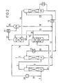
- FIGS. 1 and 2 Further details of the invention are explained below using two exemplary embodiments, the process sequence of which is shown schematically in FIGS. 1 and 2.
- a gas containing CO 2 and optionally H 2 S for example a synthesis gas containing CO 2 as acid gas
- a gas containing CO 2 and optionally H 2 S for example a synthesis gas containing CO 2 as acid gas
- a gas containing CO 2 and optionally H 2 S is introduced via line 1 under pressure into the bottom of the first absorption column 2.
- 20 to 70% strength aqueous methyldiethanolamine solution is added to the top of the first absorption column via line 5 as the absorption liquid.
- the prewashed gas obtained at the top of the first absorption column is fed via line 3 into the bottom of the second absorption column 6 for fine cleaning.
- 20 to 70% by weight aqueous methyldiethanolamine solution which is obtained from the stripping column 22 and is practically free of acid gases, is added to the top of the second absorption column via line 20 as the absorption liquid.
- the washed gas is withdrawn via line 7 at the top of the second absorption column 6.
- the aqueous absorption liquid preloaded with the acid gases at the bottom of the second absorption column is added to the top of the first absorption column 2 via lines 14 and 5 after combination with the absorption liquid obtained via lines 12 and 13 from the last expansion stage 11.
- the aqueous absorption liquid obtained at the bottom of the first absorption column 2 and loaded with CO 2 and optionally H 2 S is expanded for regeneration via line 4 in a first expansion column 8, for example via a valve or preferably via an expansion turbine.
- an intermediate expansion gas is released from the absorption liquid, which is conducted in countercurrent to the partially regenerated absorption liquid drawn off from the last expansion stage 11 via lines 9 and 10 and added to the top of the column 8, a high proportion of the acid gases contained in the expansion gas being washed out .
- the expansion gas treated with partially regenerated absorption liquid is drawn off via line 16.
- the partially relaxed absorption liquid is drawn off at the bottom of the expansion column 8 and expanded into the expansion column 11 via line 15.
- a flash gas containing the CO 2 product is drawn off via line 27, which is drawn off via line 25 after passing through the heat exchanger 17 and the separating vessel 26.
- the expanded absorption liquid drawn off at the bottom of the expansion column 11 via line 9 is, as already stated above, to a very small extent, for example in an amount of 3 to 10%, based on the total absorption liquid drawn off from the column 11, via line 10 abandoned the top of the relaxation column 8.
- the much larger part of the expanded absorption liquid is passed on via line 12 and partly returned via lines 13 and 5 to the top of the absorption column 2 and partly via line 23 to the top of the stripping column 22.
- the condensate water obtained in the separating vessel 26 is fed via line 18 to the absorption liquid to be regenerated in the stripping column 22.
- the regenerated absorption liquid obtained at the bottom of the stripping column 22 is returned to the top of the second absorption column 6 via line 20 after passing through the heat exchangers 19 and 21.
- the C0 2 and possibly H 2 S containing offgas stream obtained at the top of the stripping column 22 are appropriately fed via line 24 to the lower part of the expansion column 11.
- the procedure is as in the first exemplary embodiment, but the expansion gas drawn off at the top of the column 8 via line 16 is compressed in the compressor 28 and is added via line 29 to the feed gas supplied via line 1 of the absorption column 2 becomes.
- the loaded absorption liquid leaving the first absorption column at the bottom is fed to the first expansion column in the middle area and is released there to a pressure of 8 bar, whereby expansion gas is released.
- the upper half of the first expansion column is designed as an absorption zone by installing a packed packing.
- the absorption liquid drawn off at the bottom of the first expansion column is then expanded to a pressure of 1.25 bar in the second expansion column.
- About 6% of the expanded, partially regenerated absorption liquid obtained at the bottom of the second expansion column is fed to the upper part of the first expansion column and is conducted in counterflow to the rising expansion gas in the absorption zone of the first expansion column.
- the CO 2 product is obtained in a purity of 99.8% and a yield of 99.2%.
- a comparison test is carried out as in the example (without recirculation of the expansion gas to the first absorption column), but, in accordance with the conventional methods, the expansion gas obtained in the first expansion column is not subjected to a post-wash with regenerated absorption liquid.
- the CO 2 product drawn off at the top of the second expansion column is obtained with a purity comparable to that in the example only in a yield of 96.2%.
Abstract
Description
Die vorliegende Erfindung betrifft ein Verfahren zum Entfernen von C02 und gegebenenfalls H2S aus Gasen durch eine Gaswäsche mittels einer wäßrigen, 20 bis 70.Gew.-% Methyldiethanolamin enthaltenden Absorptionsflüssigkeit.The present invention relates to a process for removing C0 2 and optionally H 2 S from gases by gas scrubbing using an aqueous absorption liquid containing 20 to 70% by weight of methyldiethanolamine.
Bei Absorptionsverfahren zur Entfernung von C02 aus Gasen wie Synthesegasen und Erdgasen wird das abgetrennte C02 häufig als Wertprodukt gewonnen, das für weitere Zwecke Anwendung findet. Beispielsweise wird das bei der Gaswäsche von Erdgasen bzw. Erdölbegleitgasen erhaltene C02 nach Kompression in Erdöllagerstätten zurückgeführt, um hierdurch den Grad der Erdölgewinnung zu erhöhen. Weiter wird das aus dem Synthesegas einer Ammoniakanlage in einer C02-Wäsche abgetrennte C02 häufig in einer nachgeschaltenen Harnstoffanlage als Einsatzstoff für die Umsetzung mit Ammoniak zu Harnstoff verwendet. Dabei ist das in der Ammoniakanlage gewonnene C02 in der Regel gegenüber dem in der Ammoniakanlage erhaltenen Ammoniak in bezug auf die Harnstoffbildung im Unterschuß, so daß es von besonderer Bedeutung ist, daß in der C02-Wäsche der Ammoniakanlage das C02 in möglichst hoher Ausbeute gewonnen wird.In absorption processes for removing C0 2 from gases such as synthesis gases and natural gases, the separated C0 2 is often obtained as a valuable product that is used for other purposes. For example, the C0 2 obtained during gas scrubbing of natural gas or associated gas is returned to oil deposits after compression in order to increase the degree of oil production. Next, the separated from the synthesis gas of an ammonia plant in a C0 2 scrubbing C0 2 is often used in a nachgeschaltenen urea plant as starting material for reaction with ammonia to form urea. Here, the C0 2 obtained in the ammonia plant as a rule, compared to the one obtained in the ammonia plant ammonia with respect to the formation of urea in a reduced amount, so that it is of particular importance that, in the C0 2 scrubbing the ammonia plant high, the C0 2 in possible Yield is obtained.
Aus der deutschen Patentschrift 25 51 717 ist es bereits bekannt, C02 und gegebenenfalls H2S aus einem C02 und gegebenenfalls H2S enthaltenden Gas durch eine Gaswäsche mittels einer Absorptionsflüssigkeit zu entfernen, wobei die beladene Absorptionsflüssigkeit zunächst in Entspannungsstufen regeneriert und anschließend zur weiteren Regenerierung einer Abstreifkolonne zugeführt wird. Bei der Anwendung dieses Gaswaschverfahrens für die C02-Wäsche eines Ammoniaksynthesegases wird das C02 in der Regel in einer Ausbeute zwischen 95 und 97 % gewonnen, wobei die C02-Verluste - abgesehen von dem durch die C02-Spezifikation des gereinigten Gases vorgegebenen Rest-C02-Gehalt im gereinigten Gas - im wesentlichen im Abgas der ersten Entspannungsstufe auftreten.From
Aus Hydrocarbon Processing, März-Heft 1988, S. 43-46 ist bereits bekannt, bei einer solchen C02-Wäsche unter Verwendung eines physikalischen Lösungsmittels die C02-Ausbeute in der Weise zu erhöhen, daß das aus der ersten Entspannungsstufe erhaltene Gas zum Absorber zum Einsatzgas der C02-Wäsche zurückgeführt wird. Diese Arbeitsweise hat jedoch die folgenden Nachteile:
- - Die aus dem Einsatzgas unter dem relativ hohen Druck in der Absorptionskolonne auszuwaschende C02-Menge wird erhöht. Dies führt zu einer Zunahme des erforderlichen Absorptionsmittelumlaufs und dementsprechend zu einer Zunahme der Durchmesser der Absorptions- und Regenerationskolonnen.
- - Es ergibt sich weiter ein zusätzlicher Verbrauch an elektrischer Energie für die Kompression des zum Absorber zurückgeführten Gases und die Verpumpung der erhöhten Absorptionsmittelumlaufmenge.
- - Die Kühlung und Kompression der Gasströme und die größeren Kolonnen führen zu erhöhten Investitionskosten.
- - The amount of CO 2 to be washed out of the feed gas under the relatively high pressure in the absorption column is increased. This leads to an increase in the absorption medium circulation required and accordingly to an increase in the diameter of the absorption and regeneration columns.
- - There is also an additional consumption of electrical energy for the compression of the gas returned to the absorber and the pumping of the increased amount of absorbent circulating.
- - The cooling and compression of the gas streams and the larger columns lead to increased investment costs.
Es ist weiter vorgeschlagen worden, das für die Harnstoffgewinnung benötigte zusätzliche C02 durch eine C02-Wäsche aus den aus der Ammoniakanlage erhaltenen Verbrennungsgasen zu gewinnen. Wegen der in diesen Verbrennungsgasen häufig noch enthaltenen korrosiven Komponenten wie 02 und S02 entstehen in solchen CO2-Wäs- chen oft erhebliche Probleme durch Korrosion von Anlagenteilen und Zersetzung des Lösungsmittels.It has also been proposed to obtain the additional CO 2 required for urea production by CO 2 washing from the combustion gases obtained from the ammonia system. Because of the corrosive components such as 0 2 and S0 2, which are often still contained in these combustion gases, such CO 2 washes often cause considerable problems due to corrosion of system parts and decomposition of the solvent.
Es wurde nun ein vorteilhaftes Verfahren gefunden zum Entfernen von C02 und gegebenenfalls H2S aus einem C02 und gegegebenenfalls H2S enthaltenden Gas mittels einer Absorptionsflüssigkeit, bei dem man das C02 und gegebenenfalls H2S enthaltende Gas in einer Absorptionszone mit einer wäßrigen, 20 bis 70 Gew.-% Methyldiethanolamin enthaltenden Absorptionsflüssigkeit behandelt, aus der Absorptionszone das behandelte Gas abzieht, die aus der Absorptionszone erhaltene, mit C02 und gegebenenfalls H2S beladene Absorptionsflüssigkeit anschließend regeneriert, indem die mit C02 und gegebenenfalls H2S beladene Absorptionsflüssigkeit in einer oder mehreren Entspannungsstufen entspannt wird und am Kopf der ersten Entspannungsstufe bzw. bei mehreren Entspannungsstufen am Kopf mindestens einer der ersten bis vorletzten Entspannungsstufen ein Entspannungsgas abgezogen wird und die aus der letzten Entspannungsstufe erhaltene teilweise regenerierte Absorptionsflüssigkeit gegebenenfalls zur weiteren Regenerierung einer Abstreifzone zugeführt wird, wobei aus der Regenerierung mindestens ein das C02 und gegebenenfalls H2S enthaltender Sauergasstrom abgezogen wird und die regenerierte Absorptionsflüssigkeit in die Absorptionszone zurückgeführt wird, welches dadurch gekennzeichnet ist, daß mindestens einer der Entspannungsstufen, aus denen das Entspannungsgas abgezogen wird, an einer Stelle oberhalb der Zuführung der zu entspannenden Absorptionsflüssigkeit ein Teilstrom von ganz oder teilweise regenerierter Absorptionsflüssigkeit zugeführt wird.An advantageous method has now been found for removing C0 2 and optionally H 2 S from a gas containing C0 2 and optionally H 2 S by means of an absorption liquid, in which the gas containing C0 2 and optionally H 2 S is in an absorption zone with a treated aqueous absorption liquid containing 20 to 70% by weight of methyldiethanolamine, the treated gas is withdrawn from the absorption zone, the absorption liquid obtained from the absorption zone and then loaded with CO 2 and optionally H 2 S is then regenerated by using the CO 2 and optionally H 2 S loaded absorption liquid is expanded in one or more relaxation stages and a relaxation gas is drawn off at the head of the first relaxation stage or in the case of several relaxation stages on the head of at least one of the first to penultimate relaxation stages and the partially regenerated absorption liquid obtained from the last relaxation stage is given if a stripping zone is fed for further regeneration, at least one sour gas stream containing the C0 2 and possibly H 2 S being withdrawn from the regeneration and the regenerated absorption liquid being returned to the absorption zone, which is characterized in that at least one of the relaxation stages from which the expansion gas is withdrawn, a partial stream of wholly or partially regenerated absorption liquid is supplied at a point above the supply of the absorption liquid to be expanded.
Nach dem neuen Verfahren läßt sich die C02-Ausbeute beispielsweise in der C02-Wäsche einer Ammoniakanlage in einfacher Weise durch die erfindungsgemäße Nachwäsche des Entspannungsgases der entsprechenden Entspannungsstufe mit teilweise regenerierter Absorptionsflüssigkeit aus der letzten Entspannungsstufe auf über 99 % erhöhen, ohne daß hierfür die gemäß den bekannten Verfahren erforderlichen aufwendigen Maßnahmen erforderlich sind. Entsprechend der geringen Menge des C02-haltigen Entspannungsgases wird für die erfindungsgemäße Nachwäsche zum Auswaschen des C02 aus dem Entspannungsgas nur ein geringes Kolonnenvolumen benötigt, so daß die zusätzlichen Investitionskosten sehr gering sind. Da weiter nur ein kleiner Teilstrom der beispielsweise aus der letzten Entspannungsstufe durch Absenkung des Drucks erhaltenen teilweise regenerierten Absortionsflüssigkeit für die Nachwäsche benötigt wird, ändert sich der gesamte Wärmebedarf im Regenerationsteil der Sauergaswäsche durch die Nachwäsche praktisch nicht.According to the new method, the C0 2 yield an ammonia plant of the respective expansion stage with a partially regenerated absorption liquid can, for example, in the C0 2 scrubbing in a simple manner by the inventive washing-off of the expansion gas from increase the last relaxation level to over 99%, without this requiring the expensive measures required according to the known methods. In accordance with the small amount of the C0 2 -containing expansion gas, only a small column volume is required for the after-washing according to the invention for washing out the C0 2 from the expansion gas, so that the additional investment costs are very low. Since only a small partial flow of the partially regenerated absorption liquid obtained, for example, from the last relaxation stage by lowering the pressure is required for the after-washing, the total heat requirement in the regeneration part of the acid gas washing is practically not changed by the after-washing.
Als nach dem erfindungsgemäßen Verfahren zu behandelnde Gase kommen beispielsweise Kohlevergasungsgase, Koksofengase, Erdgase, Erdölbegleitgase und Synthesegase in Betracht, wobei die Anwendung auf C02-haltige Erdgase und Erd- ölbegleitgase im Hinblick auf die C02-Gewinnung für die tertiäre Erdölförderung und auf Ammoniaksynthesegase im Hinblick auf die Weiterverwendung des gewonnenen C02 für die Harnstoffherstellung von besonderem Interesse ist.Gases to be treated according to the method of the invention include, for example, coal gasification gases, coke oven gases, natural gases, associated petroleum gases and synthesis gases, the application to CO 2 -containing natural gases and associated petroleum gases with regard to the production of CO 2 for tertiary oil production and ammonia synthesis gases is of particular interest with regard to the further use of the C0 2 obtained for the production of urea.
Die Gase weisen im allgemeinen einen C02-Gehalt von 1 bis 90 Mol.%, vorzugsweise 2 bis 90 Mol.%, insbesondere 3 bis 60 Mol.% auf. Neben dem C02 können die Gase als weiteres Sauergas H2S enthalten, z.B. in Mengen von 1 Mol.ppm bis 50 Mol.%. Da jedoch das erfindungsgemäße Verfahren vorteilhaft für die Gewinnung von C02 als Wertprodukt, das in der Regel einen möglichst geringen H2S-Gehalt aufweisen soll, verwendet wird, werden Einsatzgase bevorzugt, die im allgemeinen weniger als 2 Mol.%, vorzugsweise weniger als 500 Mol.ppm, insbesondere weniger als 50 Mol.ppm, mit besonderem Vorteil weniger als 10 Mol.ppm aufweisen. Insbesondere für C02-Wäs- chen in Ammoniakanlagen werden in der Regel praktisch H2S-freie Synthesegase, z.B. mit einem H2S-Gehalt von weniger als 0,1 Mol.ppm eingesetzt.The gases generally have a CO 2 content of 1 to 90 mol%, preferably 2 to 90 mol%, in particular 3 to 60 mol%. In addition to the CO 2 , the gases may contain H 2 S as a further acid gas, for example in amounts of 1 mol.ppm to 50 mol%. However, since the process according to the invention is advantageously used for the production of CO 2 as a valuable product, which should generally have the lowest possible H 2 S content, feed gases are preferred which are generally less than 2 mol%, preferably less than 500 mol.ppm, in particular less than 50 mol.ppm, with particular advantage less than 10 mol.ppm. In particular for C0 2 washes in ammonia plants, practically H 2 S-free synthesis gases, for example with an H 2 S content of less than 0.1 mol.ppm, are generally used.
Als Absorptionsflüssigkeiten für das erfindungsgemäße Verfahren werden wäßrige Lösungen von Methyldiethanolamin verwendet, das als wäßrige Absorptionsflüssigkeit mit einem Gehalt von Methyldiethanolamin von 20 bis 70 Gew.%, vorzugsweise 30 bis 65 Gew.%, insbesondere 35 bis 60 Gew.% eingesetzt wird. In einer vorteilhaften Ausführungsform des Verfahrens verwendet man eine wäßrige Methyldiethanolaminlösung, die zusätzlich 0,05 bis 3 Mol/I, vorzugsweise 0,1 bis 2 Mol/I, insbesondere 0,1 bis 1 Mol/I eines primären Amins oder Alkanolamins wie Monoethanolamin, vorzugsweise eines sekundären Amins oder Alkanolamins, vorteilhaft Methylmonoethanolamin, ganz besonders vorteilhaft Piperazin, enthält.The absorption liquids used in the process according to the invention are aqueous solutions of methyldiethanolamine which is used as the aqueous absorption liquid with a methyldiethanolamine content of 20 to 70% by weight, preferably 30 to 65% by weight, in particular 35 to 60% by weight. In an advantageous embodiment of the process, an aqueous methyldiethanolamine solution is used which additionally contains 0.05 to 3 mol / l, preferably 0.1 to 2 mol / l, in particular 0.1 to 1 mol / l, of a primary amine or alkanolamine, such as monoethanolamine, preferably a secondary amine or alkanolamine, advantageously methylmonoethanolamine, very particularly advantageously piperazine.
Das erfindungsgemäße Verfahren wird in der Weise durchgeführt, daß das C02 und gegebenenfalls H2S enthaltende Gas in einer Absorptionszone mit der Absorptionsflüssigkeit behandelt wird. Dabei kann die Absorption in einer oder mehreren, vorzugsweise zwei, Absorptionsstufen durchgeführt werden. Bei einer Absorptionsstufe wird das zu behandelnde Gas im unteren Teil der Absorptionsstufe, vorzugsweise im unteren Drittel, zugeführt und im Gegenstrom zur Absorptionsflüssigkeit, die zweckmäßig im oberen Teil der Absorptionsstufe, vorzugsweise im oberen Drittel zugegeben wird, geführt. Die mit den Sauergasen C02 und gegebenenfalls H2S beladene Absorptionsflüssigkeit wird im unteren Teil der Absorptionszone, vorzugsweise im unteren Drittel, insbesondere am Sumpf der Absorptionszone abgezogen. Am Kopf der Absorptionsstufe wird das behandelte Gas abgezogen.The process according to the invention is carried out in such a way that the gas containing CO 2 and optionally H 2 S is treated in an absorption zone with the absorption liquid. The absorption can be carried out in one or more, preferably two, absorption stages. In the case of an absorption stage, the gas to be treated is fed in the lower part of the absorption stage, preferably in the lower third, and in countercurrent to the absorption liquid, which is expediently added in the upper part of the absorption stage, preferably in the upper third. The absorption liquid loaded with the acid gases C0 2 and optionally H 2 S is drawn off in the lower part of the absorption zone, preferably in the lower third, in particular at the bottom of the absorption zone. The treated gas is drawn off at the top of the absorption stage.
Bei der Anwendung von zwei hintereinandergeschalteten Absorptionsstufen wird das am Kopf der ersten Absorptionsstufe erhaltene Gas anschließend einer zweiten Absorptionszone zugeführt, in der es zur weiteren Entfernung von C02 und gegebenenfalls H2S mit Absorptionsflüssigkeit behandelt wird, die einen geringeren Gehalt an C02 und gegebenenfalls H2S aufweist als die der ersten Absorptionsstufe zugeführte Absorptionsflüssigkeit. Auch bezüglich der zweiten Absorptionsstufe wird das zu behandelnde Gas zweckmäßig im unteren Teil, vorzugsweise im unteren Drittel, dieser Absorptionsstufe zugeführt und im Gegenstrom zur Absorptionsflüssigkeit geführt, die zweckmäßig im oberen Teil, vorzugsweise im oberen Drittel, der zweiten Absorptionsstufe zugegeben wird. Das Produktgas wird am Kopf der zweiten Absorptionsstufe abgezogen. Die am Boden der zweiten Absorptionsstufe erhaltene mit C02 und/oder H2S vorbeladene wäßrige Absorptionsflüssigkeit wird am Kopf der ersten Absorptionsstufe zugeführt. In der ersten und zweiten Absorptionsstufe werden im allgemeinen Drucke von 2 bis 130 bar, vorzugsweise 10 bis 120 bar, insbesondere 20 bis 110 bar angewendet. Dabei können in der ersten und zweiten Stufe unterschiedliche Drucke verwendet werden. Im allgemeinen wird man jedoch in der ersten und zweiten Absorptionsstufe bei gleichem Druck bzw. bei im wesentlichen gleichem Druck arbeiten, wobei die Druckunterschiede z.B. durch den sich den den Absorptionsstufen einstellenden Druckverlust bewirkt werden. Als Absorptionsstufen werden zweckmäßig Absorptionskolonnen verwendet, im allgemeinen Füllkörperkolonnen oder mit Böden ausgestattete Kolonnen. Die mit den Sauergasen C02 und gegebenenfalls H2S beladene Absorptionsflüssigkeit wird im unteren Teil der ersten Absorptionsstufe abgezogen.When using two absorption stages connected in series, the gas obtained at the top of the first absorption stage is then fed to a second absorption zone, in which it is treated with absorption liquid for the further removal of C0 2 and optionally H 2 S, which has a lower content of C0 2 and optionally H 2 S has the absorption liquid supplied to the first absorption stage. Also with regard to the second absorption stage, the gas to be treated is expediently fed to this absorption stage in the lower part, preferably in the lower third, and guided in countercurrent to the absorption liquid, which is expediently added to the second absorption stage in the upper part, preferably in the upper third. The product gas is drawn off at the top of the second absorption stage. The aqueous absorption liquid obtained with C0 2 and / or H 2 S at the bottom of the second absorption stage is fed to the top of the first absorption stage. In the first and second absorption stages, pressures of 2 to 130 bar, preferably 10 to 120 bar, in particular 20 to 110 bar, are generally used. Different prints can be used in the first and second stages. In general, however, one will work in the first and second absorption stages at the same pressure or at substantially the same pressure, the pressure differences being caused, for example, by the pressure loss which arises in the absorption stages. Absorption columns are expediently used as absorption stages, generally packed columns or columns equipped with plates. The absorption liquid loaded with the acid gases C0 2 and possibly H 2 S is drawn off in the lower part of the first absorption stage.
Anschließend wird die aus der Absorptionszone erhaltene, mit C02 und gegebenenfalls H2S beladene Absorptionsflüssigkeit regeneriert, indem die mit C02 und gegebenenfalls H2S beladene Absorptionsflüssigkeit in einer oder mehreren, vorzugsweise zwei bis vier, insbesondere zwei oder drei, Entspannungsstufen entspannt wird, wobei am Kopf der ersten Entspannungsstufe bzw. bei mehreren Entspannungsstufen am Kopf mindestens einer der ersten bis vorletzten Entspannungsstufen ein Entspannungsgas erhalten wird. Die aus der oder den Entspannungsstufen erhaltene teilweise regenerierte Absorptionsflüssigkeit kann in die Absorptionszone zurückgeführt werden. Sie kann jedoch auch zur weiteren Regenerierung einer Abstreifzone zugeführt werden, in der die noch in diesem Strom enthaltenen Sauergase C02 und gegebenenfalls H2 S praktisch ganz ausgestreift werden. Als Ausstreifmittel kommen z.B. Wasserdampf, inerte Gase wie Stickstoff in Betracht. Falls das zu behandelnde Gas als Sauergas nur C02 enthält, d.h. frei von H2S ist, kommen als Ausstreifmittel auch Luft in Betracht. Bei einer einstufigen Absorption wird, falls die aus der oder den Entspannungsstufen erhaltene teilweise regenerierte Absorptionsflüssigkeit zur weiteren Regenerierung einer Abstreifzone zugeführt wird, die im unteren Teil der Abstreifzone erhaltene regenerierte Absorptionsflüssigkeit in die Absorptionsstufe zurückgeführt und dort zweckmäßig am Kopf der Absorptionsstufe zugegeben. Bei einer zweistufigen Absorption wird zweckmäßig die am Sumpf der letzten Entspannungsstufe erhaltene Absorptionsflüssigkeit teilweise als Waschflüssigkeit in die erste Absorptionsstufe zurückgeführt, und es wird ein weiterer Teilstrom der am Sumpf der letzten Entspannungsstufe erhaltenen Absorptionsflüssigkeit zur weiteren Regenerierung der Abstreifzone zugeführt. Die am Sumpf der Abstreifzone erhaltene ganz regenerierte Absorptionsflüssigkeit wird in die zweite Absorptionsstufe zurückgeführt und dort zweckmäßig am Kopf dieser Absorptionsstufe zugegeben.Then the absorption liquid obtained from the absorption zone and loaded with CO 2 and optionally H 2 S is regenerated by relaxing the absorption liquid loaded with CO 2 and optionally H 2 S in one or more, preferably two to four, in particular two or three, relaxation stages , wherein a relaxation gas is obtained at the head of the first relaxation stage or, in the case of a plurality of relaxation stages, at least one of the first to penultimate relaxation stages. The partially regenerated absorption liquid obtained from the relaxation step or steps can be returned to the absorption zone. However, it can also be fed to a stripping zone for further regeneration, in which the acid gases C0 2 and possibly H2 S still contained in this stream are practically completely stripped. Stripping agents include, for example, water vapor, inert gases such as nitrogen. If the gas to be treated contains only C0 2 as acid gas, ie is free of H 2 S, air can also be used as stripping agent. In the case of a single-stage absorption, if the partially regenerated absorption liquid obtained from the relaxation stage or stages is fed to a stripping zone for further regeneration, the regenerated absorption liquid obtained in the lower part of the stripping zone is returned to the absorption stage and is expediently added there at the top of the absorption stage. In the case of a two-stage absorption, the absorption liquid obtained at the bottom of the last relaxation stage is expediently returned as washing liquid to the first absorption stage, and a further partial stream of the absorption liquid obtained at the bottom of the last relaxation stage is fed to the stripping zone for further regeneration. The completely regenerated absorption liquid obtained at the bottom of the stripping zone is returned to the second absorption stage, where it is expediently added at the top of this absorption stage.
Es ist ein wesentliches Merkmal des vorliegenden Verfahrens, daß mindestens einer der Entspannungsstufen, aus denen Entspannungsgas abgezogen wird, an einer Stelle oberhalb der Zuführung der zu entspannenden Absorptionsflüssigkeit ein Teilstrom von ganz oder teilweise regenerierter Absorptionsflüssigkeit zugeführt wird. Zweckmäßig wird die ganz oder teilweise regenerierte Absorptionsflüssigkeit im oberen Teil, vorzugsweise im oberen Drittel der betreffenden Entspannungsstufe-(n) zugeführt und im Gegenstrom zu dem in der oder den betreffenden Entspannungsstufen freigesetzten Entspannungsgas geführt. Zweckmäßig ist der Raum oberhalb der Zuführung der zu entspannenden Absorptionsflüssigkeit zu der oder den Entspannungsstufen, woraus das Entspannungsgas abgezogen wird, als Absorptionszone gestaltet, d.h. man startet ihn zweckmäßig mit Füllkörperpackungen oder mit Böden aus, wodurch die Effektivität der Auswaschung des C02 und gegebenenfalls des H2S aus dem Entspannungsgas verbessert wird. Für die Auswaschung des C02 und gegebenenfalls H2S aus dem Entspannungsgas wird nur ein kleiner Teilstrom der ganz oder teilweise regenerierten Absorptionsflüssigkeit benötigt. Im allgemeinen verhalten sich der der Nachwäsche in der oder den Entspannungsstufen zugeführte Teilstrom der ganz oder teilweise regenerierten Absorptionsflüssigkeit zu dem oder der Summe aus den zur Absorptionszone zugeführten Strömen der ganz oder teilweise regenerierten Absorptionsflüssigkeit mengenmäßig zueinander wie 1:100 bis 1:2, vorzugsweise 1:80 bis 1:5, insbesondere 1:50 bis 1:10. Bei der Verwendung von mehreren Entspannungsstufen in der Regenerierung wird der erfindungsgemäßen Nachwäsche im allgemeinen ein Teilstrom von teilweise regenerierter Absorptionsflüssigkeit aus der letzten Entspannungsstufe zugeführt. Es ist jedoch auch möglich, einen Teilstrom von aus der Abstreifzone erhaltener, ganz regenerierter Absorptionsflüssigkeit für die Nachwäsche einzusetzen. Falls die Regenerierung aus einer einzelnen Entspannungsstufe und einer Abstreifzone besteht, wird der Nachwäsche in der Entspannungsstufe ein Teilstrom von aus der Abstreifzone erhaltener regenerierter Absorptionsflüssigkeit zugeführt.It is an essential feature of the present method that at least one of the expansion stages from which expansion gas is drawn off is supplied with a partial flow of wholly or partially regenerated absorption liquid at a point above the supply of the absorption liquid to be expanded. The wholly or partially regenerated absorption liquid is expediently supplied in the upper part, preferably in the upper third, of the relevant relaxation stage (s) and conducted in countercurrent to the relaxation gas released in the relevant relaxation stage (s). The space above the supply of the absorption liquid to be expanded to the expansion stage or stages from which the expansion gas is drawn off is expediently designed as an absorption zone, that is to say it is expediently started with packing or with bottoms, which increases the effectiveness of washing out the CO 2 and, if appropriate, the H 2 S from the flash gas is improved. For washing out the C0 2 and possibly H 2 S from the expansion gas, only a small partial flow of the wholly or partially regenerated absorption liquid is required. In general, the partial flow of the wholly or partly regenerated absorption liquid supplied to the after-washing in the relaxation step or steps is to the total or the sum of the flows of the wholly or partly regenerated absorption liquid supplied to the absorption zone in relation to one another in terms of quantity: 1: 100 to 1: 2, preferably 1 : 80 to 1: 5, especially 1:50 to 1:10. When using several relaxation stages in the regeneration, a partial flow of partially regenerated absorption liquid from the last relaxation stage is generally fed to the afterwash according to the invention. However, it is also possible to use a partial stream of completely regenerated absorption liquid obtained from the stripping zone for the after-washing. If the regeneration consists of a single relaxation stage and a stripping zone, a partial flow of regenerated absorption liquid obtained from the stripping zone is fed to the after-washing in the relaxation stage.
Der das C02-Produkt enthaltende Sauergasstrom wird bei Verwendung von mehreren Entspannungsstufen in der Regenerierung zweckmäßig am Kopf der letzten Entspannungsstufe und gegebenenfalls zusätzlich am Kopf des Ausstreifers abgezogen. Es ist jedoch auch möglich, zusätzlich am Kopf von einer oder mehreren der vorletzten bis zweiten Entspannungsstufe weitere das C02-Produkt enthaltende Sauergasströme abzuziehen. Bei Verwendung von einer einzelnen Entspannungsstufe und einer Abstreifzone für die Regenerierung wird der das C02-Produkt enthaltende Sauergasstrom am Kopf der Abstreifzone abgezogen.The sour gas stream containing the CO 2 product is expediently drawn off at the head of the last relaxation stage and, if appropriate, additionally at the head of the stripper when using several relaxation stages in the regeneration. However, it is also possible to additionally draw off further acid gas streams containing the CO 2 product at the top of one or more of the penultimate to second relaxation stages. When using a single relaxation stage and a stripping zone for the regeneration, the sour gas stream containing the CO 2 product is drawn off at the head of the stripping zone.
Eine weitere Ausführungsform des erfindungsgemäßen Verfahrens besteht darin, daß man das aus der oder den Entspannungsstufen abgezogene und gemäß der erfindungsgemäßen Nachwäsche mit ganz oder teilweise regenerierter Absorptionsflüssigkeit behandelte Entspannungsgas in die Absorptionszone zurückführt. Zweckmäßig wird das zurückgeführte Entspannungsgas dem der Absorptionszone zugeführten Einsatzgas zugemischt. Durch diese Maßnahme kann die C02-Ausbeute noch weiter erhöht werden. Durch die vorherige Behandlung des Entspannungsgases mit regenerierter Absorptionsflüssigkeit und die dadurch bewirkte Auswaschung der Sauergase verbleibt nur noch ein geringer Reststrom des Entspannungsgases, so daß nur ein sehr geringer Gasstrom in die Absorptionszone zurückzuführen ist.A further embodiment of the process according to the invention consists in returning the expansion gas withdrawn from the relaxation stage or stages and treated with completely or partially regenerated absorption liquid in accordance with the afterwashing according to the invention into the absorption zone. The recirculated expansion gas is expediently mixed with the feed gas fed to the absorption zone. This measure allows the CO 2 yield to be increased even further. The previous treatment of the relaxation gas with regenerated absorption liquid and the resulting washing out of the acid gases only remains still a small residual flow of the expansion gas, so that only a very small gas flow can be attributed to the absorption zone.
Nachfolgend werden weitere Einzelheiten der Erfindung anhand von zwei Ausführungsbeispielen, deren Verfahrensablauf in den Figuren 1 und 2 schematisch dargestellt ist, erläutert.Further details of the invention are explained below using two exemplary embodiments, the process sequence of which is shown schematically in FIGS. 1 and 2.
Gemäß Figur 1 wird ein C02 und gegebenenfalls H2S enthaltendes Gas, z.B. ein C02 als Sauergas enthaltendes Synthesegas, über Leitung 1 unter Druck in den Sumpf der ersten Absorptionskolonne 2 gegeben. Gleichzeitig wird über Leitung 5 als Absorptionsflüssigkeit 20 bis 70 %ige wäßrige Methyldiethanolaminlösung auf den Kopf der ersten Absorptionskolonne gegeben. Das am Kopf der ersten Absorptionskolonne erhaltene vorgewaschene Gas wird zur Feinreinigung über Leitung 3 in den Sumpf der zweiten Absorptionskolonne 6 gegeben. Gleichzeitig wird über Leitung 20 als Absorptionsflüssigkeit 20 bis 70 gew.%ige wäßrige Methyldiethanolaminlösung, die aus der Abstreifkolonne 22 erhalten wird und praktisch frei von Sauergasen ist, auf den Kopf der zweiten Absorptionskolonne gegeben. Das gewaschene Gas wird über Leitung 7 am Kopf der zweiten Absorptionskolonne 6 abgezogen. Die am Sumpfderzweiten Absorptionskolonne erhaltene mit den Sauergasen vorbeladene wäßrige Absorptionsflüssigkeit wird über Leitungen 14 und 5 nach Vereinigung mit der über Leitungen 12 und 13 aus der letzten Entspannungsstufe 11 erhaltenen Absorptionsflüssigkeit auf den Kopf der ersten Absorptionskolonne 2 gegeben. Die am Sumpf der ersten Absorptionskolonne 2 erhaltene, mit C02 und gegebenenfalls H2S beladene wäßrige Absorptionsflüssigkeit wird zur Regenerierung über Leitung 4 in einer ersten Entspannungskolonne 8 entspannt, z.B. über ein Ventil oder vorzugsweise über eine Entspannungsturbine. Hierbei wird ein Zwischenentspannungsgas aus der Absorptionsflüssigkeit freigesetzt, das im Gegenstrom zu der aus der letzten Entspannungsstufe 11 über Leitungen 9 und 10 abgezogenen, am Kopf der Kolonne 8 zugegebenen teilweise regenerierten Absorptionsflüssigkeit geführt wird, wobei ein hoher Anteil der in dem Entspannungsgas enthaltenen Sauergase ausgewaschen wird. Das mit teilweise regenerierter Absorptionsflüssigkeit behandelte Entspannungsgas wird über Leitung 16 abgezogen. Am Boden der Entspannungskolonne 8 wird die teilentspannte Absorptionsflüssigkeit abgezogen und über Leitung 15 in die Entspannungskolonne 11 entspannt. Am Kopf der Entspannungskolonne 11 wird über Leitung 27 ein das C02-Produkt enthaltendes Entspannungsgas abgezogen, das nach Passieren des Wärmetauschers 17 und des Abscheidegefäßes 26 über Leitung 25 abgezogen wird. Die am Sumpf der Entspannungskolonne 11 über Leitung 9 abgezogene entspannte Absorptionsflüssigkeit wird, wie bereits vorstehend ausgeführt, zu einem sehr geringen Anteil, z.B. in einer Menge von 3 bis 10%, bezogen auf die insgesamt aus der Kolonne 11 abgezogene Absorptionsflüssigkeit, über Leitung 10 auf den Kopf der Entspannungskolonne 8 aufgegeben. Der weitaus größere Teil der entspannten Absorptionsflüssigkeit wird über Leitung 12 weitergeführt und zu einem Teil über Leitungen 13 und 5 zum Kopf der Absorptionskolonne 2 zurückgeführt und zum anderen Teil über Leitung 23 auf den Kopf der Abstreifkolonne 22 gegeben. Das im Abscheidegefäß 26 anfallende Kondensatwasser wird über Leitung 18 der in der Abstreifkolonne 22 weiter zu regenerierenden Absorptionsflüssigkeit zugeführt.According to FIG. 1, a gas containing CO 2 and optionally H 2 S, for example a synthesis gas containing CO 2 as acid gas, is introduced via line 1 under pressure into the bottom of the
Die am Sumpf der Abstreifkolonne 22 erhaltene regenerierte Absorptionsflüssigkeit wird über Leitung 20 nach Passieren der Wärmetauscher 19 und 21 auf den Kopf der zweiten Absorptionskolonne 6 zurückgeführt. Der am Kopf der Abstreifkolonne 22 erhaltene C02 und gegebenenfalls H2S enthaltende Abgasstrom wird über Leitung 24 zweckmäßig dem unteren Teil der Entspannungskolonne 11 zugeführt. Es ist jedoch auch möglich, den am Kopf der Abstreifkolonne 22 erhaltenen Abgasstrom unmittelbar aus dem System abzuziehen, ohne ihn noch vorher der Entspannungskolonne 11 zuzuführen.The regenerated absorption liquid obtained at the bottom of the stripping
In einem weiteren Ausführungsbeispiel (vgl. Fig. 2) wird wie im ersten Ausführungsbeispiel verfahren, wobei jedoch das am Kopf der Kolonne 8 über Leitung 16 abgezogene Entspannungsgas im Kompressor 28 verdichtet wird und über Leitung 29 dem über Leitung 1 der Absorptionskolonne 2 zugeführten Einsatzgas zugegeben wird.In a further exemplary embodiment (cf. FIG. 2), the procedure is as in the first exemplary embodiment, but the expansion gas drawn off at the top of the
Das folgende Beispiel veranschaulicht die Erfindung.The following example illustrates the invention.
Man verwendet eine Gaswaschanlage entsprechend der Fig. 1 mit zwei hintereinandergeschalteten Absorptionskolonnen, zwei hintereinandergeschalteten Entspannungskolonnen und einer Abstreifkolonne. In den Absorptionskolonnen werden 6410 kmol/h eines C02-haltigen Synthesegases mit einer 40 gew.%igen wäßrigen MethyldiethanolaminLösung als Absorptionsflüssigkeit gewaschen. Das zu reinigende Synthesegas wird mit einem Druck von 35 bar am Sumpf der ersten Absorptionskolonne zugeführt. Das zu reinigende, aus einem Steam Reformer stammende Gas hat die folgende Zusammensetzung:
C0 CO 0,3 Vol.%H 2 60,3 Vol.%N CH 4 0,5 Vol.%Ar 0,3 Vol.%.
- C0 2 17.9 vol.%
- CO 0.3 vol.%
- H 2 60.3 vol.%
- N 2 20.7 vol.%
- CH 4 0.5 vol.%
- Ar 0.3% by volume.
Die Temperatur der Absorptionsflüssigkeit im Zulauf zur ersten Absorptionskolonne beträgt 73 °C. Die Temperatur der der zweiten Absorptionskolonne zugeführten Absorptionsflüssigkeit beträgt 50 ° C. Das am Kopf der zweiten Absorptionskolonne abgezogene gereinigte Synthesegas hat die folgende Zusammensetzung:
- C02 0,1 Vol.%
CO 0,4 Vol.%H 2 73,3 Vol.%N CH 4 0,6 Vol.%Ar 0,3 Vol.%.
- C0 2 0.1 vol.%
- CO 0.4 vol.%
- H 2 73.3 vol.%
- N 2 25.3 vol.%
- CH 4 0.6 vol.%
- Ar 0.3% by volume.
Die die erste Absorptionskolonne am Sumpf verlassende beladene Absortionsflüssigkeit wird der ersten Entspannungskolonne im mittleren Bereich zugeführt und dort auf einen Druck von 8 barentspannt, wobei Entspannungsgas freigesetzt wird. Die obere Hälfte der ersten Entspannungskolonne ist durch den Einbau einer Füllkörperpakkung als Absorptionszone gestaltet. Die am Boden derersten Entspannungskolonne abgezogene Absorptionsflüssigkeit wird anschließend in die zweite Entspannungskolonne auf einen Druck von 1,25 bar entspannt. Die am Boden der zweiten Entspannungskolonne erhaltene entspannte, teilregenerierte Absorptionsflüssigkeit wird zu etwa 6 % dem oberen Teil der ersten Entspannungskolonne zugeführt und wird in der Absorptionszone der ersten Entspannungskolonne im Gegenstrom zu dem aufsteigenden Entspannungsgas geführt. Am Kopf der ersten Entspannungskolonne werden 28 kmol/h des mit teilregenerierter Absorptionsflüssigkeit gewaschenen Entspannungsgases mit einem C02-Gehalt von nur 15 Vol.% abgezogen. Die verbleibende aus der zweiten Entspannungskolonne abgezogene entspannte, teilregenerierte Absorptionsflüssigkeit wird zu etwa 4/5 in die erste Absorptionskolonne zurückgeführt und zu etwa 1/5 der Abstreifkolonne zugeführt. Die aus der Abstreifkolonne erhaltene vollständig regenerierte Absorptionsflüssigkeit wird in die zweite Absorptionskolonne zurückgeführt.The loaded absorption liquid leaving the first absorption column at the bottom is fed to the first expansion column in the middle area and is released there to a pressure of 8 bar, whereby expansion gas is released. The upper half of the first expansion column is designed as an absorption zone by installing a packed packing. The absorption liquid drawn off at the bottom of the first expansion column is then expanded to a pressure of 1.25 bar in the second expansion column. About 6% of the expanded, partially regenerated absorption liquid obtained at the bottom of the second expansion column is fed to the upper part of the first expansion column and is conducted in counterflow to the rising expansion gas in the absorption zone of the first expansion column. At the top of the first expansion column, 28 kmol / h of the expansion gas having a partially regenerated absorption liquid and a CO 2 content of only 15% by volume are drawn off. About 4/5 of the remaining expanded, partially regenerated absorption liquid drawn off from the second expansion column is returned to the first absorption column and about 1/5 is fed to the stripping column. The completely regenerated absorption liquid obtained from the stripping column is returned to the second absorption column.
Am Kopf der zweiten Entspannungskolonne wird das C02-Produkt in einer Reinheit von 99,8 % und einer Ausbeute von 99,2 % erhalten.At the top of the second relaxation column, the CO 2 product is obtained in a purity of 99.8% and a yield of 99.2%.
Falls das am Kopf der ersten Entspannungskolonne abgezogene Entspannungsgas entsprechend Fig. 2 in die erste Absorptionskolonne zurückgeführt wird, erhöht sich die Ausbeute an C02-Produkt bei vergleichbarer Reinheit auf 99,5 %.If the expansion gas drawn off at the top of the first expansion column is returned to the first absorption column according to FIG. 2, the yield of CO 2 product increases to 99.5% with comparable purity.
In einem Vergleichsversuch wird wie im Beispiel (ohne Rückführung des Entspannungsgases zur ersten Absorptionskolonne) verfahren, wobei jedoch gemäß den herkömmlichen Verfahren das in der ersten Entspannungskolonne erhaltene Entspannungsgas nicht einer Nachwäsche mit regenerierter Absorptionsflüssigkeit unterzogen wird. Dabei wird das am Kopf der zweiten Entspannungskolonne abgezogene C02-Produkt bei vergleichbarer Reinheit wie im Beispiel lediglich in einer Ausbeute von 96,2% erhalten.A comparison test is carried out as in the example (without recirculation of the expansion gas to the first absorption column), but, in accordance with the conventional methods, the expansion gas obtained in the first expansion column is not subjected to a post-wash with regenerated absorption liquid. The CO 2 product drawn off at the top of the second expansion column is obtained with a purity comparable to that in the example only in a yield of 96.2%.
Claims (6)
Priority Applications (1)
| Application Number | Priority Date | Filing Date | Title |
|---|---|---|---|
| AT89115057T ATE81992T1 (en) | 1988-08-19 | 1989-08-16 | PROCESS FOR REMOVING CO2 AND APPLICABLE H2S FROM GASES. |
Applications Claiming Priority (2)
| Application Number | Priority Date | Filing Date | Title |
|---|---|---|---|
| DE3828227 | 1988-08-19 | ||
| DE3828227A DE3828227A1 (en) | 1988-08-19 | 1988-08-19 | PROCEDURE FOR REMOVING CO (ARROW ALARM) 2 (ARROW DOWN) AND, IF APPLICABLE H (ARROW ALARM) 2 (ARROW DOWN) FROM GAS |
Publications (3)
| Publication Number | Publication Date |
|---|---|
| EP0359991A1 EP0359991A1 (en) | 1990-03-28 |
| EP0359991B1 EP0359991B1 (en) | 1992-11-04 |
| EP0359991B2 true EP0359991B2 (en) | 1994-11-17 |
Family
ID=6361217
Family Applications (1)
| Application Number | Title | Priority Date | Filing Date |
|---|---|---|---|
| EP89115057A Expired - Lifetime EP0359991B2 (en) | 1988-08-19 | 1989-08-16 | Process for removing carbon dioxide and possibly hydrogen sulphide from gases |
Country Status (8)
| Country | Link |
|---|---|
| US (1) | US4999031A (en) |
| EP (1) | EP0359991B2 (en) |
| JP (1) | JP3091759B2 (en) |
| AT (1) | ATE81992T1 (en) |
| CA (1) | CA1320038C (en) |
| DE (2) | DE3828227A1 (en) |
| ES (1) | ES2036004T5 (en) |
| NO (1) | NO172477C (en) |
Families Citing this family (79)
| Publication number | Priority date | Publication date | Assignee | Title |
|---|---|---|---|---|
| US5137550A (en) * | 1991-04-26 | 1992-08-11 | Air Products And Chemicals, Inc. | Cascade acid gas removal process |
| DE4121436A1 (en) * | 1991-06-28 | 1993-01-07 | Linde Ag | METHOD FOR SELECTIVE H (DOWN ARROW) 2 (DOWN ARROW) S WASHING |
| JP2931153B2 (en) * | 1991-11-28 | 1999-08-09 | 株式会社日立製作所 | Method for removing acid gas from combustion exhaust gas |
| US5378442A (en) * | 1992-01-17 | 1995-01-03 | The Kansai Electric Power Co., Inc. | Method for treating combustion exhaust gas |
| FR2743083B1 (en) * | 1995-12-28 | 1998-01-30 | Inst Francais Du Petrole | METHOD FOR DEHYDRATION, DEACIDIFICATION AND DEGAZOLINATION OF A NATURAL GAS, USING A MIXTURE OF SOLVENTS |
| US5861051A (en) * | 1996-03-06 | 1999-01-19 | Huntsman Petrochemical Corporation | Process for removing carbon dioxide from gas mixture |
| CA2177449C (en) * | 1996-05-20 | 2003-04-29 | Barry Steve Marjanovich | Process for treating a gas stream to selectively separate acid gases therefrom |
| DE19828977A1 (en) * | 1998-06-29 | 1999-12-30 | Basf Ag | Absorbent for removing acidic components from gases |
| US6165432A (en) * | 1998-09-30 | 2000-12-26 | The Dow Chemical Company | Composition and process for removal of acid gases |
| DE19933301A1 (en) | 1999-07-15 | 2001-01-18 | Basf Ag | Process for removing mercaptans from fluid streams |
| US6203599B1 (en) | 1999-07-28 | 2001-03-20 | Union Carbide Chemicals & Plastics Technology Corporation | Process for the removal of gas contaminants from a product gas using polyethylene glycols |
| DE19947845A1 (en) * | 1999-10-05 | 2001-04-12 | Basf Ag | Processes for removing COS from a hydrocarbon fluid stream and wash liquid for use in such processes |
| DE10028637A1 (en) * | 2000-06-09 | 2001-12-13 | Basf Ag | Process for deacidifying a hydrocarbon stream comprises contacting the stream with an absorbing liquid, separating the purified stream and the absorbing liquid |
| DE10036173A1 (en) * | 2000-07-25 | 2002-02-07 | Basf Ag | Process for deacidifying a fluid stream and wash liquid for use in such a process |
| FR2814379B1 (en) * | 2000-09-26 | 2002-11-01 | Inst Francais Du Petrole | METHOD FOR DEACIDIFYING A GAS BY ABSORPTION IN A SOLVENT WITH TEMPERATURE CONTROL |
| FR2820430B1 (en) * | 2001-02-02 | 2003-10-31 | Inst Francais Du Petrole | PROCESS FOR DEACIDIFYING A GAS WITH WASHING OF DESORBED HYDROCARBONS DURING THE REGENERATION OF THE SOLVENT |
| FR2822838B1 (en) * | 2001-03-29 | 2005-02-04 | Inst Francais Du Petrole | PROCESS FOR DEHYDRATION AND FRACTIONATION OF LOW PRESSURE NATURAL GAS |
| FR2822839B1 (en) * | 2001-03-29 | 2003-05-16 | Inst Francais Du Petrole | IMPROVED PROCESS FOR DEHYDRATION AND DEGAZOLINATION OF A WET NATURAL GAS |
| DE10135370A1 (en) | 2001-07-20 | 2003-01-30 | Basf Ag | Process for removing acid gases from a gas stream |
| KR100516498B1 (en) * | 2001-12-10 | 2005-09-23 | 주식회사 포스코 | Improved h2s scrubbing method in cokes oven gas using ammonia water and mdea |
| DE10229750B4 (en) * | 2002-07-03 | 2007-03-29 | Lurgi Ag | Plant unit and method for the desorption of carbon dioxide from methanol |
| DE10306254A1 (en) | 2003-02-14 | 2004-08-26 | Basf Ag | Absorbent for removing acid gases from fluids, e.g. carbon dioxide, hydrogen sulfide, carbonyl sulfide and mercaptans from various gases, contains tertiary alkanolamine(s) plus mono- and/or bis-(hydroxyethylpiperazine |
| MXPA05010039A (en) * | 2003-03-21 | 2005-10-26 | Dow Global Technologies Inc | Improved composition and method for removal of carbonyl sulfide from acid gas containing same. |
| ES2384712T3 (en) * | 2003-04-04 | 2012-07-11 | Board Of Regents, The University Of Texas System | Alkaline / polyamine salt mixtures for the extraction of carbon dioxide in gas streams |
| US20060156923A1 (en) * | 2003-06-05 | 2006-07-20 | Basf Aktiengesellschaft | Method for the deacidification of a fluid stream by means of an inert scrubbing column and corresponding device |
| JP2005000827A (en) * | 2003-06-12 | 2005-01-06 | Toshiba Corp | Apparatus and method for recovering carbon dioxide |
| BRPI0514141A (en) * | 2004-08-06 | 2008-05-27 | Eig Inc | Ultra-flue gas cleaning including CO2 removal |
| DE102005033837B4 (en) | 2005-07-20 | 2019-02-28 | Basf Se | Process for removing acidic gases and ammonia from a fluid stream |
| JP2009530073A (en) * | 2006-03-16 | 2009-08-27 | ビーエーエスエフ ソシエタス・ヨーロピア | Method of contacting two phases with two-phase contact accompanied by heat generation |
| JP4971433B2 (en) * | 2006-05-18 | 2012-07-11 | ビーエーエスエフ ソシエタス・ヨーロピア | Removal of acidic gases from fluid streams with reduced co-absorption of hydrocarbons and oxygen |
| WO2008025743A1 (en) * | 2006-08-28 | 2008-03-06 | Basf Se | Removal of carbon dioxide from combustion exhaust gases |
| KR100804399B1 (en) * | 2006-09-06 | 2008-02-15 | 주식회사 포스코 | Apparatus and method of h2s removal from blast furnace slag by amine compounds |
| FR2916652B1 (en) * | 2007-05-30 | 2009-07-24 | Inst Francais Du Petrole | PROCESS FOR INTEGRATED TREATMENT OF A NATURAL GAS FOR COMPLETE DEACIDIFICATION |
| US8182577B2 (en) * | 2007-10-22 | 2012-05-22 | Alstom Technology Ltd | Multi-stage CO2 removal system and method for processing a flue gas stream |
| US7862788B2 (en) | 2007-12-05 | 2011-01-04 | Alstom Technology Ltd | Promoter enhanced chilled ammonia based system and method for removal of CO2 from flue gas stream |
| AU2009216164B2 (en) * | 2008-02-22 | 2011-10-13 | Mitsubishi Heavy Industries, Ltd. | Apparatus for recovering CO2 and method of recovering CO2 |
| US20090282977A1 (en) * | 2008-05-14 | 2009-11-19 | Alstom Technology Ltd | Gas purification system having provisions for co2 injection of wash water |
| US7846240B2 (en) * | 2008-10-02 | 2010-12-07 | Alstom Technology Ltd | Chilled ammonia based CO2 capture system with water wash system |
| US8404027B2 (en) * | 2008-11-04 | 2013-03-26 | Alstom Technology Ltd | Reabsorber for ammonia stripper offgas |
| EP2391437B1 (en) | 2009-01-29 | 2013-08-28 | Basf Se | Absorbent comprising amino acid and acidic promoter for acid gas removal |
| DE102009012452A1 (en) * | 2009-03-12 | 2010-09-16 | Uhde Gmbh | A method for reducing olefin losses in the removal of carbon dioxide from an olefin stream from dehydrogenation reactions |
| US8292989B2 (en) * | 2009-10-30 | 2012-10-23 | Alstom Technology Ltd | Gas stream processing |
| US8221712B2 (en) | 2009-05-12 | 2012-07-17 | Basf Se | Absorption medium for the selective removal of hydrogen sulfide from fluid streams |
| WO2010136425A1 (en) * | 2009-05-26 | 2010-12-02 | Basf Se | Process for recovery of carbon dioxide from a fluid stream, in particular from syngas |
| US8784761B2 (en) * | 2009-11-20 | 2014-07-22 | Alstom Technology Ltd | Single absorber vessel to capture CO2 |
| US8790605B2 (en) * | 2009-09-15 | 2014-07-29 | Alstom Technology Ltd | Method for removal of carbon dioxide from a process gas |
| US8309047B2 (en) | 2009-09-15 | 2012-11-13 | Alstom Technology Ltd | Method and system for removal of carbon dioxide from a process gas |
| US8518156B2 (en) * | 2009-09-21 | 2013-08-27 | Alstom Technology Ltd | Method and system for regenerating a solution used in a wash vessel |
| EA023174B1 (en) * | 2009-11-02 | 2016-04-29 | Эксонмобил Апстрим Рисерч Компани | Cryogenic system for removing acid gases from a hydrocarbon gas stream, with removal of hydrogen sulfide |
| EP2322265A1 (en) | 2009-11-12 | 2011-05-18 | Alstom Technology Ltd | Flue gas treatment system |
| US8293200B2 (en) * | 2009-12-17 | 2012-10-23 | Alstom Technology Ltd | Desulfurization of, and removal of carbon dioxide from, gas mixtures |
| US8728209B2 (en) | 2010-09-13 | 2014-05-20 | Alstom Technology Ltd | Method and system for reducing energy requirements of a CO2 capture system |
| US8623307B2 (en) | 2010-09-14 | 2014-01-07 | Alstom Technology Ltd. | Process gas treatment system |
| JP5717112B2 (en) * | 2010-09-26 | 2015-05-13 | 中国科学院過程工程研究所 | Ionic liquid solvent and gas purification method |
| US8329128B2 (en) | 2011-02-01 | 2012-12-11 | Alstom Technology Ltd | Gas treatment process and system |
| US9028784B2 (en) | 2011-02-15 | 2015-05-12 | Alstom Technology Ltd | Process and system for cleaning a gas stream |
| AU2012228245B2 (en) | 2011-03-16 | 2016-06-16 | Nov Process & Flow Technologies As | Method and system for gas purification with first direct absorption step and second absorption step by means of membrane contactor |
| US9162177B2 (en) | 2012-01-25 | 2015-10-20 | Alstom Technology Ltd | Ammonia capturing by CO2 product liquid in water wash liquid |
| WO2013136310A1 (en) | 2012-03-16 | 2013-09-19 | Aker Process Systems As | Hydrocarbon gas treatment |
| US8864879B2 (en) | 2012-03-30 | 2014-10-21 | Jalal Askander | System for recovery of ammonia from lean solution in a chilled ammonia process utilizing residual flue gas |
| US9447996B2 (en) | 2013-01-15 | 2016-09-20 | General Electric Technology Gmbh | Carbon dioxide removal system using absorption refrigeration |
| KR20150120976A (en) * | 2013-02-19 | 2015-10-28 | 지멘스 악티엔게젤샤프트 | Process and apparatus for processing a gas stream, especially for processing a natural gas stream |
| JP2015000372A (en) * | 2013-06-14 | 2015-01-05 | 株式会社東芝 | Acid gas recovery system |
| CN105848757B (en) * | 2013-11-07 | 2018-01-02 | 康世富技术公司 | The method of capture sulfur dioxide from gas stream |
| US8986640B1 (en) | 2014-01-07 | 2015-03-24 | Alstom Technology Ltd | System and method for recovering ammonia from a chilled ammonia process |
| CN106794414B (en) | 2014-08-25 | 2020-11-06 | 巴斯夫欧洲公司 | Removal of hydrogen sulfide and carbon dioxide from fluid streams |
| EP3185990B1 (en) | 2014-08-25 | 2018-10-17 | Basf Se | Removal of carbon dioxide from a fluid flow, using a tert butylamine and an activator |
| EP2990090A1 (en) | 2014-08-25 | 2016-03-02 | Basf Se | Absorbent for the selective removal of hydrogen sulphide from a fluid stream |
| WO2016030277A1 (en) | 2014-08-25 | 2016-03-03 | Basf Se | Diamine having tert-alkylamino group and primary amino group for use in gas scrubbing |
| BR112018003733A2 (en) | 2015-09-29 | 2018-09-25 | Basf Se | absorbent for the selective removal of hydrogen sulfide from a fluid stream and process for removing acid gases from a fluid stream |
| JP2018531147A (en) | 2015-09-29 | 2018-10-25 | ビーエーエスエフ ソシエタス・ヨーロピアBasf Se | Method for selective removal of hydrogen sulfide |
| US10493398B2 (en) | 2015-09-29 | 2019-12-03 | Basf Se | Cyclic amine for selectively removing hydrogen sulphide |
| JP6945617B2 (en) | 2016-04-25 | 2021-10-06 | ビーエイエスエフ・ソシエタス・エウロパエアBasf Se | Use of morpholinic hindered amine compounds to selectively remove hydrogen sulfide |
| WO2017211932A1 (en) | 2016-06-10 | 2017-12-14 | Basf Se | Cyclohexandiamines for use in gas scrubbing |
| US11173446B2 (en) | 2017-02-10 | 2021-11-16 | Basf Se | Process for removal of acid gases from a fluid stream |
| EP3624922B1 (en) | 2017-05-15 | 2021-07-07 | Basf Se | Absorbent, process for producing it and process for selectively removing hydrogen sulfide using it |
| US11458433B2 (en) | 2017-09-04 | 2022-10-04 | Basf Se | Absorbent and process for selectively removing hydrogen sulfide |
| ES2952010T3 (en) | 2019-02-18 | 2023-10-26 | Basf Se | Process for the removal of acid gases from a fluid stream with a liquid absorbent comprising a piperazine ring |
| CN114173908A (en) | 2019-09-10 | 2022-03-11 | 巴斯夫欧洲公司 | Process for removing acid gases from a fluid stream |
Family Cites Families (5)
| Publication number | Priority date | Publication date | Assignee | Title |
|---|---|---|---|---|
| JPS579183B2 (en) * | 1974-03-05 | 1982-02-19 | ||
| US4741884A (en) * | 1981-11-13 | 1988-05-03 | Phillips Petroleum Company | Process and apparatus for removing H2 S from gas streams |
| FR2589752B1 (en) * | 1985-10-04 | 1987-12-11 | Elf Aquitaine | METHOD AND DEVICE FOR THE SELECTIVE EXTRACTION OF H2S FROM A GAS CONTAINING IT |
| IT1190356B (en) * | 1985-05-24 | 1988-02-16 | Snam Progetti | ORIOGENIC PROCEDURE FOR SELECTIVE REMOVAL OF ACID GASES FROM GAS MIXTURES BY SOLVENT |
| NL8600030A (en) * | 1986-01-09 | 1987-08-03 | Shell Int Research | REMOVAL OF ACID GASES FROM A GAS MIX. |
-
1988
- 1988-08-19 DE DE3828227A patent/DE3828227A1/en not_active Withdrawn
-
1989
- 1989-08-11 US US07/392,410 patent/US4999031A/en not_active Expired - Lifetime
- 1989-08-16 AT AT89115057T patent/ATE81992T1/en not_active IP Right Cessation
- 1989-08-16 ES ES89115057T patent/ES2036004T5/en not_active Expired - Lifetime
- 1989-08-16 EP EP89115057A patent/EP0359991B2/en not_active Expired - Lifetime
- 1989-08-16 DE DE8989115057T patent/DE58902611D1/en not_active Expired - Lifetime
- 1989-08-17 CA CA000608616A patent/CA1320038C/en not_active Expired - Lifetime
- 1989-08-18 NO NO893322A patent/NO172477C/en not_active IP Right Cessation
- 1989-08-18 JP JP01211575A patent/JP3091759B2/en not_active Expired - Fee Related
Also Published As
| Publication number | Publication date |
|---|---|
| US4999031A (en) | 1991-03-12 |
| ES2036004T5 (en) | 1995-08-16 |
| JPH02111414A (en) | 1990-04-24 |
| CA1320038C (en) | 1993-07-13 |
| EP0359991B1 (en) | 1992-11-04 |
| DE3828227A1 (en) | 1990-02-22 |
| ES2036004T3 (en) | 1993-05-01 |
| JP3091759B2 (en) | 2000-09-25 |
| NO893322D0 (en) | 1989-08-18 |
| DE58902611D1 (en) | 1992-12-10 |
| NO172477C (en) | 1993-07-28 |
| EP0359991A1 (en) | 1990-03-28 |
| ATE81992T1 (en) | 1992-11-15 |
| NO893322L (en) | 1990-02-20 |
| NO172477B (en) | 1993-04-19 |
Similar Documents
| Publication | Publication Date | Title |
|---|---|---|
| EP0359991B2 (en) | Process for removing carbon dioxide and possibly hydrogen sulphide from gases | |
| EP0121109B1 (en) | Process for the removal of co2 and/or h2s from gases | |
| EP0159495B1 (en) | Process for the removal of co2 and/or h2s from gases | |
| EP0107046B1 (en) | Process for the removal of co2 and, when present, h2s from natural gases | |
| EP0190434A2 (en) | Process for removing CO2 and/or H2S from gases | |
| EP3390354B1 (en) | Method for the provision of carbon dioxide for the synthesis of urea | |
| DE1494809C3 (en) | Process for scrubbing carbon dioxide from low-sulfur or sulfur-free gases | |
| EP0202600A2 (en) | Process for eliminating carbon dioxide and/or hydrogen sulfide from gases | |
| DE2527985B2 (en) | Continuous process for the production of pure ammonia | |
| EP1289625B1 (en) | Method for neutralising a stream of hydrocarbon fluid | |
| DE102017222030A1 (en) | Process for the provision of CO2 for the synthesis of urea from smoke and synthesis gas | |
| EP0160203B1 (en) | Process for eliminating co2 and/or h2s from gases | |
| DD202129A5 (en) | METHOD FOR REMOVING CARBON DIOXIDE AND, IF ANY, SULFUR HYDROGEN FROM A GAS MIXTURE | |
| DE1567717A1 (en) | Process for the fine purification of gases containing hydrogen | |
| EP2951273A1 (en) | Method and device for generating fuel for a gas turbine | |
| DE1568845A1 (en) | Process for the production of urea from ammonia and carbon dioxide | |
| EP0172408A2 (en) | Process for removal of Co2 and/or H2S from gases | |
| EP0284121A1 (en) | Process for treating two loaded currents of washing liquids | |
| DE2800491A1 (en) | PROCESS FOR THE SELECTIVE DESULFURIZATION OF A GAS MIXTURE | |
| EP0173908A2 (en) | Process for eliminating CO2 and/or H2S from gases | |
| DE2759123A1 (en) | Removal of acid gases from waste gas mixts. - by washing with an organic liquid containing ammonia | |
| EP0107783B1 (en) | Process for the removal of co2 and/or h2s from gases | |
| DE2440456C3 (en) | Process for the purification of a methane-rich gas contaminated with carbon dioxide | |
| EP0294564B1 (en) | Process for the reduction of the nh3-methanol-emission of an ammonia synthesis plant | |
| DE3100388C2 (en) |
Legal Events
| Date | Code | Title | Description |
|---|---|---|---|
| PUAI | Public reference made under article 153(3) epc to a published international application that has entered the european phase |
Free format text: ORIGINAL CODE: 0009012 |
|
| AK | Designated contracting states |
Kind code of ref document: A1 Designated state(s): AT BE DE ES FR GB IT NL SE |
|
| 17P | Request for examination filed |
Effective date: 19900308 |
|
| 17Q | First examination report despatched |
Effective date: 19920121 |
|
| GRAA | (expected) grant |
Free format text: ORIGINAL CODE: 0009210 |
|
| AK | Designated contracting states |
Kind code of ref document: B1 Designated state(s): AT BE DE ES FR GB IT NL SE |
|
| REF | Corresponds to: |
Ref document number: 81992 Country of ref document: AT Date of ref document: 19921115 Kind code of ref document: T |
|
| ITF | It: translation for a ep patent filed |
Owner name: ING. C. GREGORJ S.P.A. |
|
| REF | Corresponds to: |
Ref document number: 58902611 Country of ref document: DE Date of ref document: 19921210 |
|
| GBT | Gb: translation of ep patent filed (gb section 77(6)(a)/1977) | ||
| ET | Fr: translation filed | ||
| PLBI | Opposition filed |
Free format text: ORIGINAL CODE: 0009260 |
|
| 26 | Opposition filed |
Opponent name: LINDE AKTIENGESELLSCHAFT Effective date: 19930804 |
|
| NLR1 | Nl: opposition has been filed with the epo |
Opponent name: LINDE AKTIENGESELLSCHAFT |
|
| PUAH | Patent maintained in amended form |
Free format text: ORIGINAL CODE: 0009272 |
|
| STAA | Information on the status of an ep patent application or granted ep patent |
Free format text: STATUS: PATENT MAINTAINED AS AMENDED |
|
| 27A | Patent maintained in amended form |
Effective date: 19941117 |
|
| AK | Designated contracting states |
Kind code of ref document: B2 Designated state(s): AT BE DE ES FR GB IT NL SE |
|
| ITF | It: translation for a ep patent filed |
Owner name: ING. C. GREGORJ S.P.A. |
|
| GBTA | Gb: translation of amended ep patent filed (gb section 77(6)(b)/1977) |
Effective date: 19941130 |
|
| ET3 | Fr: translation filed ** decision concerning opposition | ||
| NLR2 | Nl: decision of opposition | ||
| EAL | Se: european patent in force in sweden |
Ref document number: 89115057.5 |
|
| NLR3 | Nl: receipt of modified translations in the netherlands language after an opposition procedure | ||
| REG | Reference to a national code |
Ref country code: ES Ref legal event code: DC2A Kind code of ref document: T5 Effective date: 19950816 |
|
| PGFP | Annual fee paid to national office [announced via postgrant information from national office to epo] |
Ref country code: ES Payment date: 19980819 Year of fee payment: 10 |
|
| PGFP | Annual fee paid to national office [announced via postgrant information from national office to epo] |
Ref country code: SE Payment date: 19990716 Year of fee payment: 11 |
|
| PGFP | Annual fee paid to national office [announced via postgrant information from national office to epo] |
Ref country code: AT Payment date: 19990722 Year of fee payment: 11 |
|
| PGFP | Annual fee paid to national office [announced via postgrant information from national office to epo] |
Ref country code: DE Payment date: 19990804 Year of fee payment: 11 |
|
| PGFP | Annual fee paid to national office [announced via postgrant information from national office to epo] |
Ref country code: BE Payment date: 19990813 Year of fee payment: 11 |
|
| PG25 | Lapsed in a contracting state [announced via postgrant information from national office to epo] |
Ref country code: AT Free format text: LAPSE BECAUSE OF NON-PAYMENT OF DUE FEES Effective date: 20000816 |
|
| PG25 | Lapsed in a contracting state [announced via postgrant information from national office to epo] |
Ref country code: SE Free format text: LAPSE BECAUSE OF NON-PAYMENT OF DUE FEES Effective date: 20000817 Ref country code: ES Free format text: LAPSE BECAUSE OF NON-PAYMENT OF DUE FEES Effective date: 20000817 |
|
| PG25 | Lapsed in a contracting state [announced via postgrant information from national office to epo] |
Ref country code: DE Free format text: LAPSE BECAUSE OF THE APPLICANT RENOUNCES Effective date: 20000819 |
|
| PG25 | Lapsed in a contracting state [announced via postgrant information from national office to epo] |
Ref country code: BE Free format text: LAPSE BECAUSE OF NON-PAYMENT OF DUE FEES Effective date: 20000831 |
|
| BERE | Be: lapsed |
Owner name: BASF A.G. Effective date: 20000831 |
|
| EUG | Se: european patent has lapsed |
Ref document number: 89115057.5 |
|
| REG | Reference to a national code |
Ref country code: GB Ref legal event code: IF02 |
|
| REG | Reference to a national code |
Ref country code: ES Ref legal event code: FD2A Effective date: 20010911 |
|
| PGFP | Annual fee paid to national office [announced via postgrant information from national office to epo] |
Ref country code: NL Payment date: 20050803 Year of fee payment: 17 |
|
| PG25 | Lapsed in a contracting state [announced via postgrant information from national office to epo] |
Ref country code: NL Free format text: LAPSE BECAUSE OF NON-PAYMENT OF DUE FEES Effective date: 20070301 |
|
| NLV4 | Nl: lapsed or anulled due to non-payment of the annual fee |
Effective date: 20070301 |
|
| PGFP | Annual fee paid to national office [announced via postgrant information from national office to epo] |
Ref country code: IT Payment date: 20080827 Year of fee payment: 20 Ref country code: FR Payment date: 20080818 Year of fee payment: 20 |
|
| PGFP | Annual fee paid to national office [announced via postgrant information from national office to epo] |
Ref country code: GB Payment date: 20080827 Year of fee payment: 20 |
|
| REG | Reference to a national code |
Ref country code: GB Ref legal event code: PE20 Expiry date: 20090815 |
|
| PG25 | Lapsed in a contracting state [announced via postgrant information from national office to epo] |
Ref country code: GB Free format text: LAPSE BECAUSE OF EXPIRATION OF PROTECTION Effective date: 20090815 |