EP0359854A1 - Tachometer device for an electromotor with windings on the rotor - Google Patents
Tachometer device for an electromotor with windings on the rotor Download PDFInfo
- Publication number
- EP0359854A1 EP0359854A1 EP88115494A EP88115494A EP0359854A1 EP 0359854 A1 EP0359854 A1 EP 0359854A1 EP 88115494 A EP88115494 A EP 88115494A EP 88115494 A EP88115494 A EP 88115494A EP 0359854 A1 EP0359854 A1 EP 0359854A1
- Authority
- EP
- European Patent Office
- Prior art keywords
- rotor
- measuring device
- speed measuring
- sensor
- stator
- Prior art date
- Legal status (The legal status is an assumption and is not a legal conclusion. Google has not performed a legal analysis and makes no representation as to the accuracy of the status listed.)
- Withdrawn
Links
Images
Classifications
-
- G—PHYSICS
- G01—MEASURING; TESTING
- G01P—MEASURING LINEAR OR ANGULAR SPEED, ACCELERATION, DECELERATION, OR SHOCK; INDICATING PRESENCE, ABSENCE, OR DIRECTION, OF MOVEMENT
- G01P3/00—Measuring linear or angular speed; Measuring differences of linear or angular speeds
- G01P3/42—Devices characterised by the use of electric or magnetic means
- G01P3/44—Devices characterised by the use of electric or magnetic means for measuring angular speed
- G01P3/48—Devices characterised by the use of electric or magnetic means for measuring angular speed by measuring frequency of generated current or voltage
- G01P3/481—Devices characterised by the use of electric or magnetic means for measuring angular speed by measuring frequency of generated current or voltage of pulse signals
- G01P3/486—Devices characterised by the use of electric or magnetic means for measuring angular speed by measuring frequency of generated current or voltage of pulse signals delivered by photo-electric detectors
-
- G—PHYSICS
- G01—MEASURING; TESTING
- G01P—MEASURING LINEAR OR ANGULAR SPEED, ACCELERATION, DECELERATION, OR SHOCK; INDICATING PRESENCE, ABSENCE, OR DIRECTION, OF MOVEMENT
- G01P3/00—Measuring linear or angular speed; Measuring differences of linear or angular speeds
- G01P3/42—Devices characterised by the use of electric or magnetic means
- G01P3/44—Devices characterised by the use of electric or magnetic means for measuring angular speed
- G01P3/48—Devices characterised by the use of electric or magnetic means for measuring angular speed by measuring frequency of generated current or voltage
- G01P3/481—Devices characterised by the use of electric or magnetic means for measuring angular speed by measuring frequency of generated current or voltage of pulse signals
- G01P3/487—Devices characterised by the use of electric or magnetic means for measuring angular speed by measuring frequency of generated current or voltage of pulse signals delivered by rotating magnets
-
- H—ELECTRICITY
- H02—GENERATION; CONVERSION OR DISTRIBUTION OF ELECTRIC POWER
- H02K—DYNAMO-ELECTRIC MACHINES
- H02K11/00—Structural association of dynamo-electric machines with electric components or with devices for shielding, monitoring or protection
- H02K11/20—Structural association of dynamo-electric machines with electric components or with devices for shielding, monitoring or protection for measuring, monitoring, testing, protecting or switching
- H02K11/21—Devices for sensing speed or position, or actuated thereby
- H02K11/215—Magnetic effect devices, e.g. Hall-effect or magneto-resistive elements
-
- H—ELECTRICITY
- H02—GENERATION; CONVERSION OR DISTRIBUTION OF ELECTRIC POWER
- H02K—DYNAMO-ELECTRIC MACHINES
- H02K11/00—Structural association of dynamo-electric machines with electric components or with devices for shielding, monitoring or protection
- H02K11/20—Structural association of dynamo-electric machines with electric components or with devices for shielding, monitoring or protection for measuring, monitoring, testing, protecting or switching
- H02K11/21—Devices for sensing speed or position, or actuated thereby
- H02K11/22—Optical devices
-
- H—ELECTRICITY
- H02—GENERATION; CONVERSION OR DISTRIBUTION OF ELECTRIC POWER
- H02K—DYNAMO-ELECTRIC MACHINES
- H02K23/00—DC commutator motors or generators having mechanical commutator; Universal AC/DC commutator motors
- H02K23/66—Structural association with auxiliary electric devices influencing the characteristic of, or controlling, the machine, e.g. with impedances or switches
Definitions
- the invention relates to a speed measuring device for a rotor-wound electric motor according to the preamble of claim 1; such an electric motor is known from DE-PS 35 29 483.
- Electric motors of the aforementioned known type are e.g. used as a mains-powered universal motor for speed-controlled small drives for household appliances such as washing machines, vacuum cleaners, hand mixers etc. and as a DC-powered commutator motor drive for auxiliary motor drives such as fans, window regulators etc.
- a mains-powered universal motor for speed-controlled small drives for household appliances such as washing machines, vacuum cleaners, hand mixers etc.
- a DC-powered commutator motor drive for auxiliary motor drives such as fans, window regulators etc.
- Tachogenerators externally coupled to the rotor shaft are generally known.
- tachometer generators consist of a separate magnetic or optical raster wheel rotating with the rotor of the motor and an associated sensor, both parts generally being accommodated in a separate housing.
- a detection of the instantaneous speed and / or possibly the direction of rotation should be made possible for rotor-wound electric motors of the type mentioned at the outset in a structurally simpler, in particular less expensive to manufacture and assemble, but nevertheless reliable manner.
- the provided insulating washer eliminates the need for special additional holding and housing components and can usually be carried out without complex specific design adjustments to the components that are actually used and without significant additional installation space, while at the same time housing-protected and possibly necessary moisture-proof accommodation due to the arrangement of the components within the existing one Motor housing is automatically guaranteed with.
- the insulating disk as a magnetic pole wheel, it is provided according to one embodiment of the invention to admix a plastic-bindable magnetic material, in particular ferrite particles, to the plastic used for injection molding the insulating disk, which after the hardening of the plastic before or after the motor-side assembly of the insulating disk in a simple manner are magnetizable.
- a plastic-bindable magnetic material in particular ferrite particles
- the insulating disk When the insulating disk is used as an optical pole wheel, it is sufficient in a particularly simple manner to produce the insulating disk from a material of such brightness that, for the optical sensor, it is possible to distinguish between the brightness of the rotor tooth covers and the winding material filling the gaps between the rotor tooth covers.
- a changing pole sequence is expediently provided for the pole wheel, which corresponds precisely to the number of rotor tooth covers or the intervening slot gaps on the outer edge of the insulating disk.
- the sensors can be held in the tangential gaps between the partial shell magnets in a structurally and technically particularly inexpensive manner.
- At least one sensor with an associated speed-indicating insulating disk and the sensor on one end face relative to the sensor on the other end face, based on the pole pitch of the pole wheel is arranged offset on the circumference.
- the sensors of both end faces can be arranged in the same gap between two partial shell magnets in order to ensure a sufficient offset, based on the pole pitch of the pole wheel, for detecting the direction of rotation.
- the stator 1 shows a e.g. from a motor vehicle electrical system powered commutator motor for driving a motor vehicle fan.
- the stator 1 essentially consists of a stator housing 11 with partial shell magnets 12, 13 held on its inner circumference for permanent magnetic stator excitation and end shields 14, 15 attached to both ends of the stator housing 11.
- the rotor 2, which is rotatably mounted in the bearings 14, 15, consists essentially of a rotor shaft 21, a commutator 27 fastened thereon, ground by brushes 28, 29, and a rotor laminated core 22 held on the rotor shaft 21 with a rotor winding with end windings inserted in its grooves 23.24. Between the end faces of the rotor laminated core 22 and the winding heads 23, 24 of the rotor winding, an insulating disk 25 or 26 is provided.
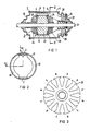
- FIG. 3 shows an enlarged illustration of a single insulating washer 25 made of plastic, the plastic of which magnetizable ferrite particles are admixed, which are magnetized in such a way that an alternating pole sequence N; S arises in accordance with the tooth-like pole tooth covers distributed over the circumference.
- a magnetically influenceable sensor 3 is assigned to the magnetic pole wheel formed in this way, with the use of the insulating end disk 25, which is located in the gaps between the tangential end faces of the partial shell magnets 12, 13, preferably between the legs of the partial shell magnets 12 that are open at the end , 13 tangentially spreading and thereby pressing against the inner circumference of the stator housing bow springs 5,6 is held in a manner not described here.
- a magnetic sensor 4 is also held on the stator side on the other end according to FIG. 1 and accordingly also on the the other end of the rotor laminated core 22, the insulating disk 26 is designed as a magnetic pole wheel.
- both magnetic sensors 3 and 4 are axially aligned in the same tangential gap between the partial shell magnets 12, 13, a set of rotor laminations with non-axially aligned grooves is assumed in the above-mentioned embodiment in a manner not shown here, so that in spite of this axially Magnetic sensors lying in the same direction with respect to the pole pitch of the insulating disk 25 relative to the pole pitch of the insulating disk 26 provide a relative mutual offset of the sensors 3 and 4 which is sufficient for the detection of the direction of rotation.
Landscapes
- Engineering & Computer Science (AREA)
- Power Engineering (AREA)
- Microelectronics & Electronic Packaging (AREA)
- Physics & Mathematics (AREA)
- General Physics & Mathematics (AREA)
Abstract
Description
Die Erfindung bezieht sich auf eine Drehzahlmeßvorrichtung für einen rotorbewickelten Elektromotor gemäß Oberbegriff des Anspruchs 1; ein derartiger Elektromotor ist durch die DE-PS 35 29 483 bekannt.The invention relates to a speed measuring device for a rotor-wound electric motor according to the preamble of claim 1; such an electric motor is known from DE-PS 35 29 483.
Elektromotoren der vorgenannten bekannten Art werden z.B. als netzgespeiste Universalmotoren für drehzahlgeregelte Kleinantriebe für Haushaltsgeräte, wie Waschmaschinen, Staubsauger, Handmixer etc. und als gleichstromgespeiste Kommutatormotorantriebe für Kraftfahrzeug-Hilfsantriebe, wie Ventilatoren, Fensterheber etc. benutzt. Zur Erfassung des jeweiligen Drehzahl-Istwertes ist die Verwendung von z.B. an die Rotorwelle extern angekoppelter Tachogeneratoren allgemein bekannt.Electric motors of the aforementioned known type are e.g. used as a mains-powered universal motor for speed-controlled small drives for household appliances such as washing machines, vacuum cleaners, hand mixers etc. and as a DC-powered commutator motor drive for auxiliary motor drives such as fans, window regulators etc. To record the respective actual speed value, the use of e.g. Tachogenerators externally coupled to the rotor shaft are generally known.
Diese Tachogeneratoren bestehen aus einem gesonderten, mit dem Rotor des Motors drehenden magnetischen oder optischen Rasterrad und einem zugeordneten Sensor, wobei beide Teile im allgemeinen in einem gesonderten Gehäuse untergebracht sind.These tachometer generators consist of a separate magnetic or optical raster wheel rotating with the rotor of the motor and an associated sensor, both parts generally being accommodated in a separate housing.
Gemäß Aufgabe vorliegender Erfindung soll für rotorbewickelte Elektromotoren der eingangs genannten Art auf konstruktiv einfachere, insbesondere fertigungs- und montagetechnisch aufwandsärmere und trotzdem betriebssichere Weise eine Erfassung der jeweils augenblicklichen Drehzahl und/oder gegebenenfalls Drehrichtung ermöglicht werden.According to the object of the present invention, a detection of the instantaneous speed and / or possibly the direction of rotation should be made possible for rotor-wound electric motors of the type mentioned at the outset in a structurally simpler, in particular less expensive to manufacture and assemble, but nevertheless reliable manner.
Die Lösung dieser Aufgabe gelingt bei einem rotorbewickelten Elektromotor der eingangs genannten Art erfindungsgemäß durch die Lehre des Anspruchs 1; vorteilhafte Ausgestaltungen der Erfindung sind jeweils Gegenstand der Unteransprüche.This object is achieved in a rotor-wound electric motor of the type mentioned in the invention by the teaching of claim 1; advantageous embodiments of the invention are the subject of the dependent claims.
Die erfindungsgemäße Integration der für die Drehzahl- und/oder Drehrichtungserkennung notwendige ruhenden Bauteile in Form von Sensoren innerhalb des an sich vorhandenen Stators und der rotierenden Bauteile in Form von magnetischen oder optischen Polen eines Polrades unter Benutzung der an sich vorhandenen, jedoch für einen anderen Verwendungszweck vorgesehenen Isolierendscheibe erübrigt besondere zusätzliche Halte- und Gehäusebauteile und ist in der Regel ohne aufwendige spezifische Konstruktionsanpassungen der an sich vorhandenen mitbenutzten Bauteile und ohne wesentlichen zusätzlichen Einbauraum durchführbar, wobei gleichzeitig eine gehäusegeschützte und gegebenenfalls notwendige feuchtigkeitsdichte Unterbringung durch die Anordnung der Bauteile innerhalb des an sich vorhandenen Motorgehäuses automatisch mit gewährleistet ist.The inventive integration of the stationary components required for the speed and / or direction of rotation detection in the form of sensors within the stator, which is present per se, and the rotating components in the form of magnetic or optical poles of a pole wheel, using those which are present per se, but for a different purpose The provided insulating washer eliminates the need for special additional holding and housing components and can usually be carried out without complex specific design adjustments to the components that are actually used and without significant additional installation space, while at the same time housing-protected and possibly necessary moisture-proof accommodation due to the arrangement of the components within the existing one Motor housing is automatically guaranteed with.
Zur Ausbildung der Isolierendscheibe als magnetisches Polrad ist nach einer Ausgestaltung der Erfindung vorgesehen, dem zum Spritzen der Isolierendscheibe verwendeten Kunststoff ein kunststoffbindbares Magnetmaterial, insbesondere Ferrit-Partikel, beizumischen, die nach dem Erhärten des Kunststoffes vor oder nach der motorseitigen Montage der Isolierendscheibe auf einfache Weise magnetisierbar sind.To form the insulating disk as a magnetic pole wheel, it is provided according to one embodiment of the invention to admix a plastic-bindable magnetic material, in particular ferrite particles, to the plastic used for injection molding the insulating disk, which after the hardening of the plastic before or after the motor-side assembly of the insulating disk in a simple manner are magnetizable.
Bei Mitbenutzung der Isolierendscheibe als optisches Polrad genügt es in besonders einfacher Weise, die Isolierendscheibe aus einem Material solcher Helligkeit herzustellen, daß in für den optischen Sensor hinreichender Unterscheidungsmöglichkeit eine Helligkeitserkennung der Rotorzahnabdeckungen gegenüber dem die zwischen den Rotorzahnabdeckungen liegenden Lücken ausfüllenden Wickelmaterial erkennbar ist. Zweckmäßigerweise wird eine wechselnde Polfolge für das Polrad vorgesehen, die gerade der Zahl der Rotorzahnabdeckungen bzw. der zwischenliegenden Nutlücken am Außenrand der Isolierendscheibe entspricht.When the insulating disk is used as an optical pole wheel, it is sufficient in a particularly simple manner to produce the insulating disk from a material of such brightness that, for the optical sensor, it is possible to distinguish between the brightness of the rotor tooth covers and the winding material filling the gaps between the rotor tooth covers. A changing pole sequence is expediently provided for the pole wheel, which corresponds precisely to the number of rotor tooth covers or the intervening slot gaps on the outer edge of the insulating disk.
Bei Verwendung eines statorseitig permanentmagnetisch erregten Universal- bzw. Kommutatormotors mittels über den Umfang des Statorgehäuses in gegenseitigem tangentialen Abstand gehalterten Teilschalenmagneten kann in konstruktiv und fertigungstechnisch besonders aufwandsarmer Weise eine Halterung der Sensoren in den tangentialen Lücken zwischen den Teilschalenmagneten vorgesehen sein.If a universal or commutator motor excited permanently on the stator side is used by means of partial shell magnets which are held at a mutual tangential distance over the circumference of the stator housing, the sensors can be held in the tangential gaps between the partial shell magnets in a structurally and technically particularly inexpensive manner.
Um auf einfache Weise auch eine Drehrichtungserkennung zu ermöglichen, ist nach einer Ausgestaltung der Erfindung vorgesehen, daß an jeder Stirnseite des Statorblechpaketes zumindest ein Sensor mit zugeordneter drehzahlgegebener Isolierendscheibe und der Sensor der einen Stirnseite gegenüber dem Sensor der anderen Stirnseite, bezogen auf die Polteilung des Polrades, am Umfang versetzt angeordnet ist. Bei einem Rotor mit sogenanntem geschränkten Rotorblechpaket, d.h. nicht axial fluchtend verlaufenden Nuten, können die Sensoren beider Stirnseiten in der gleichen Lücke zwischen zwei Teilschalenmagneten angeordnet sein, um einen hinreichenden Versatz, bezogen auf die Polteilung des Polrades, für eine Drehrichtungserkennung zu gewährleisten.In order to enable a direction of rotation detection in a simple manner, it is provided according to one embodiment of the invention that on each end face of the stator laminated core at least one sensor with an associated speed-indicating insulating disk and the sensor on one end face relative to the sensor on the other end face, based on the pole pitch of the pole wheel , is arranged offset on the circumference. In the case of a rotor with a so-called set of rotor laminations, i.e. not axially aligned grooves, the sensors of both end faces can be arranged in the same gap between two partial shell magnets in order to ensure a sufficient offset, based on the pole pitch of the pole wheel, for detecting the direction of rotation.
Die Erfindung sowie vorteilhafte weitere Ausgestaltungen der Erfindung werden im folgenden anhand eines schematisch dargestellten Ausführungsbeispieles in der Zeichnung näher erläutert; darin zeigen:
- FIG 1 einen axialen Längsschnitt durch einen Kommutatormotor mit permanenterregtem Stator gemäß Schnittverlauf I-I in FIG 2,
- FIG 2 eine stirnseitige Draufsicht auf den Statorteil des in FIG 1 dargestellten Kommutatormotors gemäß Ansicht I-I in FIG 1,
- FIG 3 in vergrößerter Darstellung eine einzelne, als magnetisches Polrad mitbenutzte Isolierendscheibe.
- 1 shows an axial longitudinal section through a commutator motor with a permanently excited stator according to section II in FIG. 2,
- 2 shows an end view of the stator part of the commutator motor shown in FIG. 1 according to view II in FIG. 1,
- 3 shows an enlarged illustration of a single insulating disk which is also used as a magnetic pole wheel.
FIG 1 zeigt einen z.B. aus einem Kraftfahrzeug-Bordnetz gespeisten Kommutatormotor zum Antrieb eines Kraftfahrzeug-Ventilators. Der Stator 1 besteht im wesentlichen aus einem Statorgehäuse 11 mit an dessen innerem Umfang gehalterten Teilschalenmagneten 12,13 für eine permanentmagnetische Statorerregung und an beiden Stirnseiten des Statorgehäuses 11 befestigten Lagerschilde 14,15. Der in von den Lagerschilden 14,15 aufgenommenen Lagern drehbar gelagerte Rotor 2 besteht im wesentlichen aus einer Rotorwelle 21, darauf befestigtem, von Bürsten 28,29 beschliffenen Kommutator 27 und auf der Rotorwelle 21 gehalterten Rotorblechpaket 22 mit in dessen Nuten eingebrachter Rotorwicklung mit stirnseitigen Wickelköpfen 23,24. Zwischen den Stirnseiten des Rotorblechpaketes 22 und den Wickelköpfen 23,24 der Rotorwicklung ist je eine Isolierendscheibe 25 bzw.26 vorgesehen.1 shows a e.g. from a motor vehicle electrical system powered commutator motor for driving a motor vehicle fan. The stator 1 essentially consists of a
FIG 3 zeigt in vergrößerter Darstellung eine einzelne, aus Kunststoff hergestellte Isolierendscheibe 25, deren Kunststoff magnetisierbare Ferrit-Partikel beigemischt sind, die derart magnetisiert sind, daß eine wechselnde Polfolge N;S entsprechend den zahnartig über den Umfang verteilten Polzahnabdekkungen entsteht. Dem derart unter Mitbenutzung der an sich vorhandenen Isolierendscheibe 25 gebildeten magnetischen Polrad ist gemäß FIG 1,2 statorseitig ein magnetisch beeinflußbarer Sensor 3 zugeordnet, der in den Lücken zwischen den tangentialen Stirnseiten der Teilschalenmagneten 12,13 vorzugsweise zwischen den stirnseitig offenen Schenkeln der die Teilschalenmagnete 12,13 tangential spreizenden und dadurch an den Innenumfang des Statorgehäuses andrückende Bügelfedern 5,6 in hier nicht näher beschriebener Weise gehalten ist.3 shows an enlarged illustration of a single
Um nicht nur eine Drehzahl- sondern auch eine Drehrichtungserkennung mit einfachen Mitteln ermöglichen zu können, ist gemäß FIG 1 auch an der anderen Stirnseite statorseitig ein magnetischer Sensor 4 gehaltert und entsprechend auch an der anderen Stirnseite des Rotorblechpaketes 22 die Isolierendscheibe 26 als magnetisches Polrad ausgebildet. Da beide magnetischen Sensoren 3 bzw.4 axial fluchtend in der gleichen tangentialen Lücke zwischen den Teilschalenmagneten 12,13 angeordnet sind, wird in vorgenanntem Ausführungsbeispiel in hier nicht näher dargestellter Weise ein geschränktes Rotorblechpaket mit nicht axial fluchtend verlaufenden Nuten vorausgesetzt, so daß insofern trotz axial in gleicher Richtung liegenden magnetischen Sensoren bezogen auf die Polteilung der Isolierendscheibe 25 relativ zur Polteilung der Isolierendscheibe 26 ein für die Drehrichtungserkennung hinreichender relativer gegenseitiger Versatz der Sensoren 3 bzw.4 gegeben ist.In order to enable not only speed but also rotation direction detection with simple means, a magnetic sensor 4 is also held on the stator side on the other end according to FIG. 1 and accordingly also on the the other end of the rotor laminated
Claims (7)
Priority Applications (1)
| Application Number | Priority Date | Filing Date | Title |
|---|---|---|---|
| EP88115494A EP0359854A1 (en) | 1988-09-21 | 1988-09-21 | Tachometer device for an electromotor with windings on the rotor |
Applications Claiming Priority (1)
| Application Number | Priority Date | Filing Date | Title |
|---|---|---|---|
| EP88115494A EP0359854A1 (en) | 1988-09-21 | 1988-09-21 | Tachometer device for an electromotor with windings on the rotor |
Publications (1)
| Publication Number | Publication Date |
|---|---|
| EP0359854A1 true EP0359854A1 (en) | 1990-03-28 |
Family
ID=8199346
Family Applications (1)
| Application Number | Title | Priority Date | Filing Date |
|---|---|---|---|
| EP88115494A Withdrawn EP0359854A1 (en) | 1988-09-21 | 1988-09-21 | Tachometer device for an electromotor with windings on the rotor |
Country Status (1)
| Country | Link |
|---|---|
| EP (1) | EP0359854A1 (en) |
Cited By (11)
| Publication number | Priority date | Publication date | Assignee | Title |
|---|---|---|---|---|
| EP0524384A1 (en) * | 1991-07-26 | 1993-01-27 | RICERCA ELETTROMECCANICA S.r.l | An electric motor including a connectable-disconnectable encoder comprising a hall-effect sensor arranged between the field poles of the stator |
| FR2680920A1 (en) * | 1991-08-28 | 1993-03-05 | Bosch Gmbh Robert | Electric motor with a device for detecting the position of the rotor, the speed of rotation and/or the direction of rotation |
| DE4326391A1 (en) * | 1993-08-06 | 1995-02-09 | Licentia Gmbh | Rotation identification device for a commutator motor |
| WO1997011520A1 (en) * | 1995-09-20 | 1997-03-27 | Siemens Aktiengesellschaft | Device for detecting the rotor speed or position in a continuously excited electric motor |
| WO1998027640A1 (en) * | 1996-12-17 | 1998-06-25 | Robert Bosch Gmbh | Electric motor |
| EP1003270A1 (en) * | 1998-11-19 | 2000-05-24 | Moriyama Kogyo Kabushiki Kaisha | Magnetic pole position detector and annular sheet with sheet-like magnets for a brushless DC motor |
| US6680553B1 (en) | 1998-11-19 | 2004-01-20 | Kabushiki Kaisha Moric | Rotating electrical apparatus |
| DE102007041798A1 (en) * | 2007-08-30 | 2009-03-05 | Brose Fahrzeugteile Gmbh & Co. Kg, Hallstadt | Drive for an adjustment of a motor vehicle |
| CN108405034A (en) * | 2018-04-17 | 2018-08-17 | 武汉轻工大学 | Measurement sensor and self feed back automation compensation hulling machine |
| CN108508229A (en) * | 2018-04-17 | 2018-09-07 | 武汉轻工大学 | Sensor |
| WO2023072738A1 (en) * | 2021-10-27 | 2023-05-04 | Mahle International Gmbh | Separately excited electric synchronous machine |
Citations (2)
| Publication number | Priority date | Publication date | Assignee | Title |
|---|---|---|---|---|
| DE3151558A1 (en) * | 1981-12-28 | 1983-07-07 | Rau Swf Autozubehoer | Electric motor |
| EP0259025A2 (en) * | 1986-09-03 | 1988-03-09 | Johnson Electric Industrial Manufactory Limited | Electric motor with velocity indicating device |
-
1988
- 1988-09-21 EP EP88115494A patent/EP0359854A1/en not_active Withdrawn
Patent Citations (2)
| Publication number | Priority date | Publication date | Assignee | Title |
|---|---|---|---|---|
| DE3151558A1 (en) * | 1981-12-28 | 1983-07-07 | Rau Swf Autozubehoer | Electric motor |
| EP0259025A2 (en) * | 1986-09-03 | 1988-03-09 | Johnson Electric Industrial Manufactory Limited | Electric motor with velocity indicating device |
Non-Patent Citations (1)
| Title |
|---|
| PATENT ABSTRACTS OF JAPAN * |
Cited By (14)
| Publication number | Priority date | Publication date | Assignee | Title |
|---|---|---|---|---|
| EP0524384A1 (en) * | 1991-07-26 | 1993-01-27 | RICERCA ELETTROMECCANICA S.r.l | An electric motor including a connectable-disconnectable encoder comprising a hall-effect sensor arranged between the field poles of the stator |
| FR2680920A1 (en) * | 1991-08-28 | 1993-03-05 | Bosch Gmbh Robert | Electric motor with a device for detecting the position of the rotor, the speed of rotation and/or the direction of rotation |
| DE4326391A1 (en) * | 1993-08-06 | 1995-02-09 | Licentia Gmbh | Rotation identification device for a commutator motor |
| US6091220A (en) * | 1995-09-20 | 2000-07-18 | Siemens Aktiengesellschaft | Device for detecting rotor speed or position in a continuously excited electric motor |
| WO1997011520A1 (en) * | 1995-09-20 | 1997-03-27 | Siemens Aktiengesellschaft | Device for detecting the rotor speed or position in a continuously excited electric motor |
| WO1998027640A1 (en) * | 1996-12-17 | 1998-06-25 | Robert Bosch Gmbh | Electric motor |
| EP1003270A1 (en) * | 1998-11-19 | 2000-05-24 | Moriyama Kogyo Kabushiki Kaisha | Magnetic pole position detector and annular sheet with sheet-like magnets for a brushless DC motor |
| US6680553B1 (en) | 1998-11-19 | 2004-01-20 | Kabushiki Kaisha Moric | Rotating electrical apparatus |
| DE102007041798A1 (en) * | 2007-08-30 | 2009-03-05 | Brose Fahrzeugteile Gmbh & Co. Kg, Hallstadt | Drive for an adjustment of a motor vehicle |
| CN108405034A (en) * | 2018-04-17 | 2018-08-17 | 武汉轻工大学 | Measurement sensor and self feed back automation compensation hulling machine |
| CN108508229A (en) * | 2018-04-17 | 2018-09-07 | 武汉轻工大学 | Sensor |
| CN108405034B (en) * | 2018-04-17 | 2023-09-01 | 武汉轻工大学 | Measurement sensor and self-feedback automatic compensation rice huller |
| CN108508229B (en) * | 2018-04-17 | 2023-10-27 | 武汉轻工大学 | Sensor for detecting a position of a body |
| WO2023072738A1 (en) * | 2021-10-27 | 2023-05-04 | Mahle International Gmbh | Separately excited electric synchronous machine |
Similar Documents
| Publication | Publication Date | Title |
|---|---|---|
| EP0359853B1 (en) | Electromotor drive, in particular driving servo for a vehicle | |
| CH650366A5 (en) | COLLECTORLESS DC OUTLET MOTOR. | |
| EP0307709B1 (en) | Device for detecting the rotation and/or for measuring the rotation speed of a small dc motor with permanent or electro-magnets | |
| EP0359854A1 (en) | Tachometer device for an electromotor with windings on the rotor | |
| DE9006935U1 (en) | Electric motor drive | |
| DE29906804U1 (en) | Positioning and actuator | |
| DE1948906A1 (en) | Protection generator | |
| DE3538225C2 (en) | Centrifugal pump or fan | |
| DE4128419C2 (en) | ||
| DE8811966U1 (en) | Electric motor drive, in particular adjustment drive for a motor vehicle | |
| EP1026507B1 (en) | Electric motor with rpm-monitor | |
| EP0233540B1 (en) | Arrangement and circuit for the electrical commutation of field windings | |
| DE19737702A1 (en) | Rotor position transmitter for electronically driven motors with rotors equipped with permanent magnets | |
| DE4142707C1 (en) | Single motor drive for spindle in spinning machines giving easy measurement - has rotation position detector consisting of magnet whose auxiliary field generates pulse in Hall sensor | |
| EP1081386A2 (en) | Axial flux electric motor | |
| DE4303479C2 (en) | Pump unit with a variable speed electric motor | |
| DE3933868B4 (en) | Blower with an electronically commutated drive motor | |
| DE8811965U1 (en) | Speed measuring device for a rotor-wound electric motor | |
| EP0548611B1 (en) | Electric motor with tachogenerator | |
| DE102007037447A1 (en) | Pressure regulator for slip-controlled hydraulic brake system in motor vehicle, has wireless transducer operated between measuring point and rotary sensor, and producing wireless information transmission between point and sensor | |
| DE3230283C2 (en) | ||
| EP0529131B1 (en) | Rotational speed measurement apparatus for DC motor | |
| DE3804549C2 (en) | Small fan with a fan impeller | |
| DE1937068A1 (en) | Speed-controlled DC motor with tachometer generator | |
| DE2104882A1 (en) | Fans, in particular for ventilating vehicles |
Legal Events
| Date | Code | Title | Description |
|---|---|---|---|
| PUAI | Public reference made under article 153(3) epc to a published international application that has entered the european phase |
Free format text: ORIGINAL CODE: 0009012 |
|
| AK | Designated contracting states |
Kind code of ref document: A1 Designated state(s): DE ES FR GB IT |
|
| 17P | Request for examination filed |
Effective date: 19900425 |
|
| STAA | Information on the status of an ep patent application or granted ep patent |
Free format text: STATUS: THE APPLICATION HAS BEEN WITHDRAWN |
|
| 18W | Application withdrawn |
Withdrawal date: 19910603 |
|
| R18W | Application withdrawn (corrected) |
Effective date: 19910603 |