EP0359712B1 - Self-illuminated fibre optic switch - Google Patents
Self-illuminated fibre optic switch Download PDFInfo
- Publication number
- EP0359712B1 EP0359712B1 EP89810670A EP89810670A EP0359712B1 EP 0359712 B1 EP0359712 B1 EP 0359712B1 EP 89810670 A EP89810670 A EP 89810670A EP 89810670 A EP89810670 A EP 89810670A EP 0359712 B1 EP0359712 B1 EP 0359712B1
- Authority
- EP
- European Patent Office
- Prior art keywords
- light
- actuator
- indicator
- optical
- switch according
- Prior art date
- Legal status (The legal status is an assumption and is not a legal conclusion. Google has not performed a legal analysis and makes no representation as to the accuracy of the status listed.)
- Expired - Lifetime
Links
- 239000000835 fiber Substances 0.000 title description 16
- 230000003287 optical effect Effects 0.000 claims description 25
- 238000005286 illumination Methods 0.000 description 9
- 230000006835 compression Effects 0.000 description 5
- 238000007906 compression Methods 0.000 description 5
- 238000004519 manufacturing process Methods 0.000 description 5
- 229920003023 plastic Polymers 0.000 description 5
- 239000006185 dispersion Substances 0.000 description 2
- 229920002972 Acrylic fiber Polymers 0.000 description 1
- NIXOWILDQLNWCW-UHFFFAOYSA-N acrylic acid group Chemical group C(C=C)(=O)O NIXOWILDQLNWCW-UHFFFAOYSA-N 0.000 description 1
- 230000008878 coupling Effects 0.000 description 1
- 238000010168 coupling process Methods 0.000 description 1
- 238000005859 coupling reaction Methods 0.000 description 1
- 230000003247 decreasing effect Effects 0.000 description 1
- 239000002360 explosive Substances 0.000 description 1
- 231100001261 hazardous Toxicity 0.000 description 1
- 230000020169 heat generation Effects 0.000 description 1
- 238000002347 injection Methods 0.000 description 1
- 239000007924 injection Substances 0.000 description 1
- 239000000463 material Substances 0.000 description 1
- 238000000034 method Methods 0.000 description 1
- 238000000465 moulding Methods 0.000 description 1
- 239000013307 optical fiber Substances 0.000 description 1
- 230000000717 retained effect Effects 0.000 description 1
- 239000012780 transparent material Substances 0.000 description 1
Images


Classifications
-
- G—PHYSICS
- G02—OPTICS
- G02B—OPTICAL ELEMENTS, SYSTEMS OR APPARATUS
- G02B6/00—Light guides; Structural details of arrangements comprising light guides and other optical elements, e.g. couplings
- G02B6/24—Coupling light guides
- G02B6/26—Optical coupling means
- G02B6/35—Optical coupling means having switching means
- G02B6/3502—Optical coupling means having switching means involving direct waveguide displacement, e.g. cantilever type waveguide displacement involving waveguide bending, or displacing an interposed waveguide between stationary waveguides
- G02B6/3508—Lateral or transverse displacement of the whole waveguides, e.g. by varying the distance between opposed waveguide ends, or by mutual lateral displacement of opposed waveguide ends
-
- G—PHYSICS
- G02—OPTICS
- G02B—OPTICAL ELEMENTS, SYSTEMS OR APPARATUS
- G02B6/00—Light guides; Structural details of arrangements comprising light guides and other optical elements, e.g. couplings
- G02B6/24—Coupling light guides
- G02B6/26—Optical coupling means
- G02B6/35—Optical coupling means having switching means
- G02B6/351—Optical coupling means having switching means involving stationary waveguides with moving interposed optical elements
- G02B6/3512—Optical coupling means having switching means involving stationary waveguides with moving interposed optical elements the optical element being reflective, e.g. mirror
- G02B6/3514—Optical coupling means having switching means involving stationary waveguides with moving interposed optical elements the optical element being reflective, e.g. mirror the reflective optical element moving along a line so as to translate into and out of the beam path, i.e. across the beam path
-
- G—PHYSICS
- G02—OPTICS
- G02B—OPTICAL ELEMENTS, SYSTEMS OR APPARATUS
- G02B6/00—Light guides; Structural details of arrangements comprising light guides and other optical elements, e.g. couplings
- G02B6/24—Coupling light guides
- G02B6/26—Optical coupling means
- G02B6/35—Optical coupling means having switching means
- G02B6/351—Optical coupling means having switching means involving stationary waveguides with moving interposed optical elements
- G02B6/3512—Optical coupling means having switching means involving stationary waveguides with moving interposed optical elements the optical element being reflective, e.g. mirror
- G02B6/352—Optical coupling means having switching means involving stationary waveguides with moving interposed optical elements the optical element being reflective, e.g. mirror the reflective optical element having a shaped reflective surface, e.g. a reflective element comprising several reflective surfaces or facets that function together
-
- G—PHYSICS
- G02—OPTICS
- G02B—OPTICAL ELEMENTS, SYSTEMS OR APPARATUS
- G02B6/00—Light guides; Structural details of arrangements comprising light guides and other optical elements, e.g. couplings
- G02B6/24—Coupling light guides
- G02B6/26—Optical coupling means
- G02B6/35—Optical coupling means having switching means
- G02B6/354—Switching arrangements, i.e. number of input/output ports and interconnection types
- G02B6/3544—2D constellations, i.e. with switching elements and switched beams located in a plane
- G02B6/3548—1xN switch, i.e. one input and a selectable single output of N possible outputs
- G02B6/355—1x2 switch, i.e. one input and a selectable single output of two possible outputs
-
- G—PHYSICS
- G02—OPTICS
- G02B—OPTICAL ELEMENTS, SYSTEMS OR APPARATUS
- G02B6/00—Light guides; Structural details of arrangements comprising light guides and other optical elements, e.g. couplings
- G02B6/24—Coupling light guides
- G02B6/26—Optical coupling means
- G02B6/35—Optical coupling means having switching means
- G02B6/3564—Mechanical details of the actuation mechanism associated with the moving element or mounting mechanism details
- G02B6/3568—Mechanical details of the actuation mechanism associated with the moving element or mounting mechanism details characterised by the actuating force
- G02B6/3574—Mechanical force, e.g. pressure variations
-
- G—PHYSICS
- G02—OPTICS
- G02B—OPTICAL ELEMENTS, SYSTEMS OR APPARATUS
- G02B6/00—Light guides; Structural details of arrangements comprising light guides and other optical elements, e.g. couplings
- G02B6/24—Coupling light guides
- G02B6/26—Optical coupling means
- G02B6/35—Optical coupling means having switching means
- G02B6/3564—Mechanical details of the actuation mechanism associated with the moving element or mounting mechanism details
- G02B6/358—Latching of the moving element, i.e. maintaining or holding the moving element in place once operation has been performed; includes a mechanically bistable system
Definitions
- This invention relates to the field of switches for electrical controls, and more particularly to switches which operate through fibre optic or light guided systems.
- incandescent lamps to provide such indicator lights.
- incandescent lights produce a large quantity of heat which is inefficient and potentially unsafe in closed environments such as airplanes.
- the invention as claimed is intended to remedy these problems. It provides light director in a mechanical actuator to direct light into or away from an output optical path depending on the position of the actuator. Coupling between an optical input and output path or paths are provided by a fibre optic or light-guided control system incorporated at least partly in a mechanical actuator.
- the switched light is used to control electrical circuits and to control the incidence of switched light onto a light indicator.
- the light guide is formed by the casing of the switch itself.
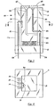
- an optical switch is illustrated generally at 10 in Figure 1. It comprises a housing lla which is made up of a casing 11 mounted on a switch base 12 and a pushbutton 13 mounted within the casing 11 and being operable to move vertically relative to the casing 11. All of the components are plastic and are moulded using injection moulded techniques.
- An illumination light is provided through a waveguide 34 mounted in switch base 12.
- Latching mechanism 40 comprises a latch groove 41 in the form of a heart, a latch 42 and a leaf spring 43 between the housing 11 and the latch 42.
- a compression spring 44 is positioned between the pushbutton 13 and the switch base 12.
- waveguide 14 is operatively connected to a sensor (not shown), the existence of light indicating to the sensor that the circuit is operating.
- the illumination light source is transmitted through waveguide 34 to illumination waveguide 23 and is transmitted off mirror 24 to illumination waveguide 25 which extends as indicated to the top of pushbutton 13.
- the top 30 simply comprises a transparent plastic material, having two sections 27 and 28 with one color, green, indicating that the illumination waveguide 25 is being travelled by light and thereby indicating the circuit is operational and a second color, red, indicating that the illumination waveguide 26 is being travelled by light and thereby indicating that the circuit is not operational.
- the latch 42 of Figure 4 will be in the position indicated. That is, it will be positioned in the upper apex of the heart shaped latch groove 41.
- the compression spring 44 will be compressed as illustrated in Figure 3.
- the pushbutton 13 will tend to move upwardly when released under the influence of compression spring 44. As it moves the latch groove 41 will move upwardly relative to the latch 42 until the latch 42 is received by the bottom apex 50 of the latch groove 41 which will retain the pushbutton 13 in this "up" position.
- the signal light will be transmitted through waveguide 15, reflected off planar surfaces 32 and out through waveguide 16.
- the signal received by the aforementioned optical sensor from waveguide 14 will cease.
- a further optical sensor may be positioned to receive the new signal from waveguide 16 if desired, thereby to indicate a new circuit condition.
- the illumination light is transmitted to the top 30 of the pushbutton 13 through waveguide 26.
- the top 27 above the waveguide 26 may be, for example, red plastic transparent material, thus indicating to the operator the condition of the interrupted circuit.
- Figure 5 discloses an embodiment of the invention in which the plastic of the casing, plunger and base form the light guide for the system.
- a plastic base 72 receives the input fibre optic cables 70 and 71. Cable 70 carries the light for the cap indicator illumination, whereas cable 71 carries a signal light beam.
- the rectangular casing 76, base 72 and plunger 78 are moulded from an optical grade acrylic plastic.
- the central rectangular plunger 78 is latched by latch 88 as previously described.
- Cap 80 attached to plunger 78 has transparent coloured indicator sections 86 and 87.
- Figure 5 shows the plunger in the "off" position.
- light entering cable 70 passes through collimating lens 90 and strikes angled shoulder 77 which causes the light beam to be internally reflected for the most part at an angle of 90 degrees.
- the light beam proceeds into the centre of clear acrylic plunger 78 and strikes surface 75 which causes the beam to be reflected a second time at a 90 degree angle.
- the plunger in the lower position the beam strikes the cap 80 at a point in the region of coloured section 87 and accordingly illumination indicating "off" status is perceived by the user.
- latch 88 When the switch is in the "on” position, latch 88 allows the plunger, biassed upwardly by spring 44, to move upwardly, and this causes the surface 75 to be moved upwardly within the casing of the switch. Consequently, the light beam is directed to impinge upon transparent coloured section 86 and the user will see a light indicating "on" status.
- Collimating lenses 90 are moulded in the casing or base of the switch to prevent dispersion of the light and allow the switch to operate without separate fibre optic cables which would increase the manufacturing cost of the switch. This factor results in significantly decreased manufacturing costs for the present invention.
- the reflecting surface 75 in the plunger is moulded as an internal reflecting surface in the plunger and needs no mirror surface.
- a first slide switch variant is shown in Figure 7 in which a light guide 100 is formed at the bottom of a slide actuator 112 which moves into or out of the paper as shown.
- the two prism reflectors of guide 100 are offset so that when in a first position light is reflected from input fibre 103 to output fibre 105 while in a second position it is reflected into output fibre 107.
Landscapes
- Physics & Mathematics (AREA)
- General Physics & Mathematics (AREA)
- Optics & Photonics (AREA)
- Mechanical Light Control Or Optical Switches (AREA)
- Push-Button Switches (AREA)
- Switch Cases, Indication, And Locking (AREA)
Description
- This invention relates to the field of switches for electrical controls, and more particularly to switches which operate through fibre optic or light guided systems.
- In certain applications, such as airplane cockpits, illuminated indicators are required for electrical switches to allow the operator to determine whether the switch is in an "on" or "off" state. Conventional switches have used incandescent lamps to provide such indicator lights. In large numbers, however, such incandescent lights produce a large quantity of heat which is inefficient and potentially unsafe in closed environments such as airplanes.
- In the past it has been known to use fibre optic controls to control the functioning of electrical devices to provide a safer system for use in wet, hospital, explosive or other hazardous environments. For example see United States Patent No. 3,999,074 which describes a fibre optic electric power control device, and United States Patent No. 4,704,656 which discloses a fibre optic switch for controlling a wall receptacle. Such devices use the fibre optic switch to provide a light signal to a photo-electric device which in turn controls the electrical circuit. In this way the fibre optic control can be made remote from the electrical circuit. For example, see also United States Patent No. 4,315,147 which describes a mechanical actuator interposed between two fibre optic lines to reversibly block light travelling from one line to the other and European Patent No. 12,274, which discloses a device where the light switch in which the actuator is a reflecting member affixed to a magnetic guide made movable in response to current applied to an electro-magnet. None of these devices have a light guide incorporated into the casing of the unit itself for ease of manufacturing. Finally, none of the known prior devices have utilized a simple mechanical actuator to switch the light into and away from an optical path.
- The invention as claimed is intended to remedy these problems. It provides light director in a mechanical actuator to direct light into or away from an output optical path depending on the position of the actuator. Coupling between an optical input and output path or paths are provided by a fibre optic or light-guided control system incorporated at least partly in a mechanical actuator. The switched light is used to control electrical circuits and to control the incidence of switched light onto a light indicator. According to one aspect of the invention, the light guide is formed by the casing of the switch itself.
- The advantages of the invention over conventional electrical control systems are less complexity, greater reliability, reduced heat generation and lower costs.
- Specific embodiments of the invention will now be described by way of example only with the use of drawings in which:
- Figure 1, is a diagrammatic partially sectional side view of a first embodiment of the optical switch according to the invention;
- Figure 2 is a diagrammatic plan sectional view of the switch of Figure 1 taken along line II-II of Figure 1;
- Figure 3 is a view of the latching mechanism used in the invention;
- Figure 4 is an enlarged view of the area VI of Figure 3;
- Figure 5 is a vertical cross-section of another embodiment of the invention; and
- Figure 6 is a cross-sectional view taken along lines VIII-VIII of Figure 5.
- Figure 7 is a cross-sectional view of a first slide switch variant according to the invention;
- Referring now to the drawings, an optical switch is illustrated generally at 10 in Figure 1. It comprises a housing lla which is made up of a
casing 11 mounted on aswitch base 12 and apushbutton 13 mounted within thecasing 11 and being operable to move vertically relative to thecasing 11. All of the components are plastic and are moulded using injection moulded techniques. - An illumination light is provided through a
waveguide 34 mounted inswitch base 12. - Referring now to Figure 3, the latching mechanism generally illustrated at 40.
Latching mechanism 40 comprises alatch groove 41 in the form of a heart, alatch 42 and aleaf spring 43 between thehousing 11 and thelatch 42. Acompression spring 44 is positioned between thepushbutton 13 and theswitch base 12. - In operation, it will be assumed that the position of the optical switch illustrated in Figure 1 is the condition under which the circuit is in a positive condition. That is, the circuit is operating.
- In this condition, the signal light source which passes through the
waveguide 33 and input optical path aswaveguide 15 is reflected off theplanar surfaces 31 and is received bywaveguide 14. Waveguide 14 is operatively connected to a sensor (not shown), the existence of light indicating to the sensor that the circuit is operating. - Likewise, the illumination light source is transmitted through
waveguide 34 toillumination waveguide 23 and is transmitted offmirror 24 toillumination waveguide 25 which extends as indicated to the top ofpushbutton 13. Thetop 30 simply comprises a transparent plastic material, having twosections illumination waveguide 25 is being travelled by light and thereby indicating the circuit is operational and a second color, red, indicating that theillumination waveguide 26 is being travelled by light and thereby indicating that the circuit is not operational. - In this condition, the
latch 42 of Figure 4 will be in the position indicated. That is, it will be positioned in the upper apex of the heart shapedlatch groove 41. Thecompression spring 44 will be compressed as illustrated in Figure 3. - It will now be assumed that the operator desires to interrupt the operation of the circuit. To do so, he will push downwardly on the
pushbutton 13. As he pushes downwardly, thelatch groove 41 will move downwardly relative to thelatch 42 and thecompression spring 44 will be further compressed until thelatch 42 is positioned in the upper area of the heart shapedlatch groove 41. Thepushbutton 13 will then be in the maximum downwards position and it will then be released. - The
pushbutton 13 will tend to move upwardly when released under the influence ofcompression spring 44. As it moves thelatch groove 41 will move upwardly relative to thelatch 42 until thelatch 42 is received by thebottom apex 50 of thelatch groove 41 which will retain thepushbutton 13 in this "up" position. - In this position and again with reference to Figure 1, the signal light will be transmitted through
waveguide 15, reflected offplanar surfaces 32 and out throughwaveguide 16. The signal received by the aforementioned optical sensor fromwaveguide 14 will cease. A further optical sensor may be positioned to receive the new signal fromwaveguide 16 if desired, thereby to indicate a new circuit condition. - With the pushbutton in the "up" position as described, the illumination light, rather than being transmitted through
waveguide 25, is transmitted to thetop 30 of thepushbutton 13 throughwaveguide 26. Thetop 27 above thewaveguide 26 may be, for example, red plastic transparent material, thus indicating to the operator the condition of the interrupted circuit. - When it is again desired to activate the circuit, the operator will again press the
pushbutton 13 until thelatch 42 is retained at theuppermost position 51 of thelatch groove 41 where it is released. Thepushbutton 13 will move upwardly under the influence ofcompression spring 44 until the position illustrated in Figure 4 is again assumed by thelatch 42 and thelatch groove 41. - Figure 5 discloses an embodiment of the invention in which the plastic of the casing, plunger and base form the light guide for the system. A
plastic base 72 receives the input fibreoptic cables Cable 70 carries the light for the cap indicator illumination, whereascable 71 carries a signal light beam. Therectangular casing 76,base 72 andplunger 78 are moulded from an optical grade acrylic plastic. The centralrectangular plunger 78 is latched bylatch 88 as previously described.Cap 80 attached toplunger 78 has transparentcoloured indicator sections - Figure 5 shows the plunger in the "off" position. In this position
light entering cable 70 passes through collimatinglens 90 and strikes angledshoulder 77 which causes the light beam to be internally reflected for the most part at an angle of 90 degrees. The light beam proceeds into the centre of clearacrylic plunger 78 and strikes surface 75 which causes the beam to be reflected a second time at a 90 degree angle. With the plunger in the lower position the beam strikes thecap 80 at a point in the region ofcoloured section 87 and accordingly illumination indicating "off" status is perceived by the user. - When the switch is in the "on" position, latch 88 allows the plunger, biassed upwardly by
spring 44, to move upwardly, and this causes thesurface 75 to be moved upwardly within the casing of the switch. Consequently, the light beam is directed to impinge upon transparentcoloured section 86 and the user will see a light indicating "on" status. - Similarly the operation of the signal beam can be seen with reference to Figures 5 and 6. When the switch is in the "off" position, the light beam travelling along
fibre optic cable 71 travels into the casing through acollimating lens 90 which prevents dispersion of the light beam. The beam is then reflected off internal reflectingsurface 91 and travels in the path shown in Figure 6. The beam reflects off internalretroreflective surfaces 92 so that it returns in a parallel but opposite and offset direction from the incoming beam and travels similarly out of the casing and through outputfibre optic cable 94. A light signal carried on this cable indicated to the electrical circuit that the circuit is in the "off" postion. When the plunger is released to the "on" position, the plunger moves upwardly in the casing and incoming light beam impinges on the lower reflectingsurface 95, shown in dotted outline in Figure 6, which causes the reflected path of the beam to be directed tooutput cable 96. A light signal onoutput cable 96 indicates to the electrical circuit that this circuit is "on". -
Collimating lenses 90 are moulded in the casing or base of the switch to prevent dispersion of the light and allow the switch to operate without separate fibre optic cables which would increase the manufacturing cost of the switch. This factor results in significantly decreased manufacturing costs for the present invention. The reflectingsurface 75 in the plunger is moulded as an internal reflecting surface in the plunger and needs no mirror surface. - A first slide switch variant is shown in Figure 7 in which a
light guide 100 is formed at the bottom of aslide actuator 112 which moves into or out of the paper as shown. The two prism reflectors ofguide 100 are offset so that when in a first position light is reflected frominput fibre 103 tooutput fibre 105 while in a second position it is reflected intooutput fibre 107. - Due to the geometry of the switch, the manufacturing tolerances for the parts of the switch need not be exact. While the critical tolerances required for operation of the switch are maintained by precise moulding of the optical and mechanical reference surface, the fit between the moving parts need not be precise. This permits simple and inexpensive manufacturing and assembly.
- As will be apparent to those skilled in the art, a number of variations of the invention as described in the preferred embodiment are possible. It is possible to substitute coated reflecting surfaces for the internal uncoated surface described. Further, a single input optical fibre may be used both for the signal and indicator lights. This would require a beam-splitting surface within the light switch body to generate the two beams. Also, other mechanical equivalents for the reciprocating motion of the plunger will be apparent, such as through use of rotary, rocker, slide, toggle or paddle switches. The scope of the invention is to be construed, however, in accordance with the following claims.
Claims (10)
- A switch for switching a beam of light, comprising,(a) a housing (11a,76)(b) an actuator (13) reversibly moveable in said housing (11a) between a first and a second position;(c) an input and two output optical paths (33,15,71,103; 14,16,94,96,105,107); and(d) two light directing means (31,32,92,95) each having at least two reflecting faces, characterised in that said light directing means are positioned on said actuator (13) such that in each of the actuator's positions a different one of said directing means is arranged so as to direct light from said input optical path (15,33,71,103) to a corresponding different one of said output optical paths (14,16,94,96,105,107).
- A switch according to claim 1, wherein said two directing means are prisms.
- A switch according to claim 2, wherein the reflecting faces of each of said prisms are orthogonal.
- A switch according to claim 2, including an input collimating lens (90) positioned so as to collimate light from said input optical path (71) onto one face of one of said prisms (92,95) so that the light is reflected onto another face of said one of said prisms and an output collimating lens positioned so as to collimate light from said another face into one of said output optical paths (94).
- A switch according to claim 1, wherein said housing (11a) is transparent.
- A switch according to claim 1, including latch means (40) for releasably holding said actuator (13) in each of said positions.
- A switch according to claim 1, including means for biasing said actuator (13) towards each of said positions.
- A switch according to claim 1, further including(a) an indicator optical input path (23,34);(b) an indicator optical output path (25) positioned to receive light from said indicator optical input path (23,34) when said actuator (13) is in a first position and not positioned to receive such light when said actuator (13) is in a second position; and(c) an indicator (28) on said actuator (13) responsive to indicate the incidence of light thereon and positioned to receive light from said indicator optical input path (23,34) via said indicator optical output path (25) when said actuator (13) is in the first position;such that said indicator (28) becomes illuminated when said actuator is in the first position.
- A switch according to claim 8, wherein said indicator (28) is translucent.
- A switch according to claim 1, futher including:(a) an indicator optical input path (34,70) in said housing (11a,76);(b) two indicator optical output paths (25,26) positioned to receive light from said indicator optical input path (34,70) when the actuator (13) is in a respective one of said positions, and(c) two indicators (28,27) on said actuator (13,78) responsive to indicate the incidence of light thereon and positioned to receive light from respective ones of said indicator optical output paths (25,26).
Applications Claiming Priority (2)
| Application Number | Priority Date | Filing Date | Title |
|---|---|---|---|
| CA577588 | 1988-09-16 | ||
| CA000577588A CA1282986C (en) | 1988-09-16 | 1988-09-16 | Self-illuminated fibre optic switch |
Publications (3)
| Publication Number | Publication Date |
|---|---|
| EP0359712A2 EP0359712A2 (en) | 1990-03-21 |
| EP0359712A3 EP0359712A3 (en) | 1991-10-23 |
| EP0359712B1 true EP0359712B1 (en) | 1997-01-29 |
Family
ID=4138737
Family Applications (1)
| Application Number | Title | Priority Date | Filing Date |
|---|---|---|---|
| EP89810670A Expired - Lifetime EP0359712B1 (en) | 1988-09-16 | 1989-09-08 | Self-illuminated fibre optic switch |
Country Status (4)
| Country | Link |
|---|---|
| US (1) | US5090791A (en) |
| EP (1) | EP0359712B1 (en) |
| CA (1) | CA1282986C (en) |
| DE (1) | DE68927729T2 (en) |
Families Citing this family (22)
| Publication number | Priority date | Publication date | Assignee | Title |
|---|---|---|---|---|
| US5214727A (en) * | 1992-01-16 | 1993-05-25 | The Trustees Of Princeton University | Electrostatic microactuator |
| US5457757A (en) * | 1992-07-13 | 1995-10-10 | Kidder; John S. | Optical control panel |
| US5410150A (en) * | 1993-01-21 | 1995-04-25 | A. J. Leisure Group Ltd. | Fiber optic controller with an interface having an emitting diode and a photodetector |
| DE4309049C2 (en) * | 1993-03-20 | 1995-04-13 | Marquardt Gmbh | Optical switching element |
| US5440655A (en) * | 1993-12-29 | 1995-08-08 | At&T Corp. | Optical fiber connector bypass device and method using same |
| FR2714886B1 (en) * | 1994-01-10 | 1996-03-29 | Labinal | Light signaling device on aircraft. |
| US5430261A (en) * | 1994-01-18 | 1995-07-04 | Eaton Corporation | Switch assembly including sequential switch rocker/lever operating mechanism |
| US5481631A (en) * | 1994-02-25 | 1996-01-02 | The Perkin-Elmer Corp. | Optical switching apparatus with retroreflector |
| US5650609A (en) * | 1995-05-15 | 1997-07-22 | Phoenix International Corporation | Seed monitoring system for counting seeds as they are dispensed through a seed planting tube |
| US6091867A (en) * | 1997-05-02 | 2000-07-18 | Neos Technologies, Inc. | M input port by N output port optical switching system |
| US5903687A (en) * | 1997-05-02 | 1999-05-11 | Neos Technologies, Inc. | M input port by N output port optical switching system |
| EP0911578A3 (en) | 1997-06-02 | 1999-07-28 | Rohm And Haas Company | Optical fiber illuminator |
| US6275626B1 (en) * | 1998-10-26 | 2001-08-14 | Herzel Laor | 1xN reflector switch |
| US6740864B1 (en) * | 2002-04-30 | 2004-05-25 | Finisar Corporation | Method and apparatus for monitoring optical switches and cross-connects |
| TWI240160B (en) * | 2004-01-29 | 2005-09-21 | Asustek Comp Inc | Electronic device with light-passed board |
| WO2006116468A2 (en) * | 2005-04-25 | 2006-11-02 | Sensata Technologies, Inc.; Power Control Business Unit | Switching device and method |
| US7928859B1 (en) | 2008-11-21 | 2011-04-19 | Yazaki North America, Inc. | Full angle laser illuminate instrument cluster |
| US7954965B1 (en) | 2009-04-13 | 2011-06-07 | Yazaki North America, Inc. | Method for multiple gauges in a scanning laser based display device |
| US8026827B1 (en) | 2009-05-04 | 2011-09-27 | Yazaki North America, Inc. | Virtual push button switch |
| DE102009051617B3 (en) * | 2009-11-02 | 2011-04-28 | Pas Deutschland Gmbh | Button for an operating arrangement, as well as operating arrangement and household appliance |
| US10237710B2 (en) | 2015-09-28 | 2019-03-19 | Eaton Intelligent Power Limited | Control system with smart devices for hazardous environments |
| WO2022029851A1 (en) * | 2020-08-03 | 2022-02-10 | 日本電信電話株式会社 | Optical switch |
Family Cites Families (11)
| Publication number | Priority date | Publication date | Assignee | Title |
|---|---|---|---|---|
| US3999074A (en) * | 1973-08-02 | 1976-12-21 | Callaghan James M | Fiber-optic photoelectric power control device |
| JPS5574503A (en) * | 1978-11-29 | 1980-06-05 | Nec Corp | Mechanical photo switch |
| US4315147A (en) * | 1980-02-15 | 1982-02-09 | Battelle Memorial Institute | Photoelectric switch with visible signal |
| US4378144A (en) * | 1980-12-22 | 1983-03-29 | Northern Telecom Limited | Optical switch |
| JPS57139704A (en) * | 1981-02-24 | 1982-08-28 | Nippon Sheet Glass Co Ltd | Optical switch |
| US4569569A (en) * | 1982-03-31 | 1986-02-11 | Plessey Overseas Limited | Optical coupling devices |
| DE3439905A1 (en) * | 1984-10-31 | 1986-04-30 | Siemens AG, 1000 Berlin und 8000 München | Rotary switch for optical fibres |
| US4726646A (en) * | 1985-02-20 | 1988-02-23 | E. I. Du Pont De Nemours And Company | Optical switch |
| FR2581204B1 (en) * | 1985-04-29 | 1988-08-26 | Thomson Csf Mat Tel | 1 BY N OPTICAL SELECTOR WITH MECHANICAL CONTROL, FOR MULTIMODE FIBERS |
| US4789215A (en) * | 1986-04-18 | 1988-12-06 | Northern Telecom Limited | Fiber optic switch with prism mounted for reciprocal and rotational movement |
| US4704656A (en) * | 1986-10-27 | 1987-11-03 | Leviton Manufacturing Company, Inc. | Fiber optic wiring device control system |
-
1988
- 1988-09-16 CA CA000577588A patent/CA1282986C/en not_active Expired
-
1989
- 1989-09-06 US US07/403,373 patent/US5090791A/en not_active Expired - Fee Related
- 1989-09-08 DE DE68927729T patent/DE68927729T2/en not_active Expired - Fee Related
- 1989-09-08 EP EP89810670A patent/EP0359712B1/en not_active Expired - Lifetime
Also Published As
| Publication number | Publication date |
|---|---|
| EP0359712A3 (en) | 1991-10-23 |
| DE68927729D1 (en) | 1997-03-13 |
| DE68927729T2 (en) | 1997-07-17 |
| US5090791A (en) | 1992-02-25 |
| EP0359712A2 (en) | 1990-03-21 |
| CA1282986C (en) | 1991-04-16 |
Similar Documents
| Publication | Publication Date | Title |
|---|---|---|
| US5090791A (en) | Self-illuminated fibre optic switch | |
| US5150257A (en) | High reliability, low intensity back lit SR and NVGC indicator assembly | |
| EP0151022B1 (en) | Manual input apparatus for providing inputs to data handling apparatus | |
| CA1076675A (en) | Optical multifunction control system for a vehicle | |
| TWI618105B (en) | Photoelectric integrated mechanical axis keyboard switch module | |
| US3157771A (en) | Lighted push button switch assembly | |
| EP0012274B1 (en) | Mechanical optical switching device | |
| EP0324228A2 (en) | Elevator control switch and position indicator assembly | |
| JPS5831562B2 (en) | Optical switch for optical fiber | |
| US5046806A (en) | Single fibre control switches | |
| GB1568205A (en) | Fibre optic switch | |
| US4385221A (en) | Illuminating device for a push-button switch | |
| US4146856A (en) | Shutterless fiber optic switch | |
| US4899260A (en) | Optical conductor body for illuminating indication elements of electrical apparatuses | |
| US3780248A (en) | Electrical switches | |
| US5986792A (en) | Lighting system sequencer and method | |
| GB1495808A (en) | Switches | |
| WO1989009515A1 (en) | Electronic push-button switch | |
| US6665465B2 (en) | Optical switch | |
| SU726666A1 (en) | Contact-free change-over switch with mechanical drive | |
| JP2645140B2 (en) | Operation display of electromagnetic contactor | |
| JPH08241658A (en) | Light-sensitive switch | |
| GB2197087A (en) | Optical switch comprising movable reflective liquid | |
| GB2234387A (en) | An operating mode selector for a magnetic tape recording and/or reproducing apparatus | |
| SU1698978A1 (en) | Static optoelectronic switch with light indication |
Legal Events
| Date | Code | Title | Description |
|---|---|---|---|
| PUAI | Public reference made under article 153(3) epc to a published international application that has entered the european phase |
Free format text: ORIGINAL CODE: 0009012 |
|
| AK | Designated contracting states |
Kind code of ref document: A2 Designated state(s): DE FR GB IT |
|
| PUAL | Search report despatched |
Free format text: ORIGINAL CODE: 0009013 |
|
| AK | Designated contracting states |
Kind code of ref document: A3 Designated state(s): DE FR GB IT |
|
| 17P | Request for examination filed |
Effective date: 19920630 |
|
| 17Q | First examination report despatched |
Effective date: 19940425 |
|
| GRAG | Despatch of communication of intention to grant |
Free format text: ORIGINAL CODE: EPIDOS AGRA |
|
| GRAH | Despatch of communication of intention to grant a patent |
Free format text: ORIGINAL CODE: EPIDOS IGRA |
|
| GRAH | Despatch of communication of intention to grant a patent |
Free format text: ORIGINAL CODE: EPIDOS IGRA |
|
| GRAA | (expected) grant |
Free format text: ORIGINAL CODE: 0009210 |
|
| AK | Designated contracting states |
Kind code of ref document: B1 Designated state(s): DE FR GB IT |
|
| PG25 | Lapsed in a contracting state [announced via postgrant information from national office to epo] |
Ref country code: IT Free format text: LAPSE BECAUSE OF FAILURE TO SUBMIT A TRANSLATION OF THE DESCRIPTION OR TO PAY THE FEE WITHIN THE PRE;WARNING: LAPSES OF ITALIAN PATENTS WITH EFFECTIVE DATE BEFORE 2007 MAY HAVE OCCURRED AT ANY TIME BEFORE 2007. THE CORRECT EFFECTIVE DATE MAY BE DIFFERENT FROM THE ONE RECORDED.SCRIBED TIME-LIMIT Effective date: 19970129 |
|
| REF | Corresponds to: |
Ref document number: 68927729 Country of ref document: DE Date of ref document: 19970313 |
|
| ET | Fr: translation filed | ||
| PLBE | No opposition filed within time limit |
Free format text: ORIGINAL CODE: 0009261 |
|
| STAA | Information on the status of an ep patent application or granted ep patent |
Free format text: STATUS: NO OPPOSITION FILED WITHIN TIME LIMIT |
|
| 26N | No opposition filed | ||
| PGFP | Annual fee paid to national office [announced via postgrant information from national office to epo] |
Ref country code: GB Payment date: 20000905 Year of fee payment: 12 |
|
| PGFP | Annual fee paid to national office [announced via postgrant information from national office to epo] |
Ref country code: DE Payment date: 20000923 Year of fee payment: 12 |
|
| PGFP | Annual fee paid to national office [announced via postgrant information from national office to epo] |
Ref country code: FR Payment date: 20000929 Year of fee payment: 12 |
|
| PG25 | Lapsed in a contracting state [announced via postgrant information from national office to epo] |
Ref country code: GB Free format text: LAPSE BECAUSE OF NON-PAYMENT OF DUE FEES Effective date: 20010908 |
|
| GBPC | Gb: european patent ceased through non-payment of renewal fee |
Effective date: 20010908 |
|
| PG25 | Lapsed in a contracting state [announced via postgrant information from national office to epo] |
Ref country code: DE Free format text: LAPSE BECAUSE OF NON-PAYMENT OF DUE FEES Effective date: 20020501 |
|
| PG25 | Lapsed in a contracting state [announced via postgrant information from national office to epo] |
Ref country code: FR Free format text: LAPSE BECAUSE OF NON-PAYMENT OF DUE FEES Effective date: 20020531 |
|
| REG | Reference to a national code |
Ref country code: FR Ref legal event code: ST |