EP0359660B1 - Optische Kontrolle von Mikrobohrungen einer Turbinenschaufel - Google Patents
Optische Kontrolle von Mikrobohrungen einer Turbinenschaufel Download PDFInfo
- Publication number
- EP0359660B1 EP0359660B1 EP89402495A EP89402495A EP0359660B1 EP 0359660 B1 EP0359660 B1 EP 0359660B1 EP 89402495 A EP89402495 A EP 89402495A EP 89402495 A EP89402495 A EP 89402495A EP 0359660 B1 EP0359660 B1 EP 0359660B1
- Authority
- EP
- European Patent Office
- Prior art keywords
- blade
- signals
- piece
- holes
- image
- Prior art date
- Legal status (The legal status is an assumption and is not a legal conclusion. Google has not performed a legal analysis and makes no representation as to the accuracy of the status listed.)
- Expired - Lifetime
Links
- 230000003287 optical effect Effects 0.000 title claims description 10
- 238000000034 method Methods 0.000 claims description 22
- 238000005553 drilling Methods 0.000 claims description 11
- 238000012545 processing Methods 0.000 claims description 10
- 238000004458 analytical method Methods 0.000 claims description 9
- 230000006870 function Effects 0.000 claims description 9
- 238000004364 calculation method Methods 0.000 claims description 4
- 239000006185 dispersion Substances 0.000 claims description 4
- 238000009499 grossing Methods 0.000 claims description 3
- 239000000463 material Substances 0.000 claims description 3
- 230000005540 biological transmission Effects 0.000 claims description 2
- 238000002310 reflectometry Methods 0.000 claims description 2
- 238000006243 chemical reaction Methods 0.000 claims 1
- 230000005055 memory storage Effects 0.000 claims 1
- 239000002184 metal Substances 0.000 description 7
- 229910052751 metal Inorganic materials 0.000 description 7
- PXHVJJICTQNCMI-UHFFFAOYSA-N Nickel Chemical compound [Ni] PXHVJJICTQNCMI-UHFFFAOYSA-N 0.000 description 6
- 238000005259 measurement Methods 0.000 description 4
- 230000005855 radiation Effects 0.000 description 4
- 238000010521 absorption reaction Methods 0.000 description 3
- 229910045601 alloy Inorganic materials 0.000 description 3
- 239000000956 alloy Substances 0.000 description 3
- 238000010586 diagram Methods 0.000 description 3
- 230000005484 gravity Effects 0.000 description 3
- 230000035699 permeability Effects 0.000 description 3
- XKRFYHLGVUSROY-UHFFFAOYSA-N Argon Chemical compound [Ar] XKRFYHLGVUSROY-UHFFFAOYSA-N 0.000 description 2
- 239000008186 active pharmaceutical agent Substances 0.000 description 2
- 229910052804 chromium Inorganic materials 0.000 description 2
- 230000007547 defect Effects 0.000 description 2
- 238000001514 detection method Methods 0.000 description 2
- 238000000605 extraction Methods 0.000 description 2
- 229910000816 inconels 718 Inorganic materials 0.000 description 2
- 229910052759 nickel Inorganic materials 0.000 description 2
- 239000013307 optical fiber Substances 0.000 description 2
- 238000004451 qualitative analysis Methods 0.000 description 2
- 241001415961 Gaviidae Species 0.000 description 1
- 241000287107 Passer Species 0.000 description 1
- 229920000297 Rayon Polymers 0.000 description 1
- 241001080024 Telles Species 0.000 description 1
- 229910052786 argon Inorganic materials 0.000 description 1
- 230000001427 coherent effect Effects 0.000 description 1
- 238000002485 combustion reaction Methods 0.000 description 1
- 238000001816 cooling Methods 0.000 description 1
- 238000009826 distribution Methods 0.000 description 1
- 238000001914 filtration Methods 0.000 description 1
- 238000007689 inspection Methods 0.000 description 1
- 229910052742 iron Inorganic materials 0.000 description 1
- 238000004519 manufacturing process Methods 0.000 description 1
- 230000015654 memory Effects 0.000 description 1
- 150000002739 metals Chemical class 0.000 description 1
- 229910052758 niobium Inorganic materials 0.000 description 1
- 238000003672 processing method Methods 0.000 description 1
- 238000003908 quality control method Methods 0.000 description 1
- 238000004445 quantitative analysis Methods 0.000 description 1
- 239000002964 rayon Substances 0.000 description 1
- 238000012552 review Methods 0.000 description 1
- 230000035945 sensitivity Effects 0.000 description 1
- 238000000926 separation method Methods 0.000 description 1
- 238000003860 storage Methods 0.000 description 1
- 230000001629 suppression Effects 0.000 description 1
- 229910052721 tungsten Inorganic materials 0.000 description 1
- 238000011144 upstream manufacturing Methods 0.000 description 1
- 238000009423 ventilation Methods 0.000 description 1
- 238000012795 verification Methods 0.000 description 1
- 230000000007 visual effect Effects 0.000 description 1
Images


Classifications
-
- G—PHYSICS
- G01—MEASURING; TESTING
- G01N—INVESTIGATING OR ANALYSING MATERIALS BY DETERMINING THEIR CHEMICAL OR PHYSICAL PROPERTIES
- G01N21/00—Investigating or analysing materials by the use of optical means, i.e. using sub-millimetre waves, infrared, visible or ultraviolet light
- G01N21/84—Systems specially adapted for particular applications
- G01N21/88—Investigating the presence of flaws or contamination
- G01N21/95—Investigating the presence of flaws or contamination characterised by the material or shape of the object to be examined
- G01N21/956—Inspecting patterns on the surface of objects
- G01N21/95692—Patterns showing hole parts, e.g. honeycomb filtering structures
-
- B—PERFORMING OPERATIONS; TRANSPORTING
- B23—MACHINE TOOLS; METAL-WORKING NOT OTHERWISE PROVIDED FOR
- B23Q—DETAILS, COMPONENTS, OR ACCESSORIES FOR MACHINE TOOLS, e.g. ARRANGEMENTS FOR COPYING OR CONTROLLING; MACHINE TOOLS IN GENERAL CHARACTERISED BY THE CONSTRUCTION OF PARTICULAR DETAILS OR COMPONENTS; COMBINATIONS OR ASSOCIATIONS OF METAL-WORKING MACHINES, NOT DIRECTED TO A PARTICULAR RESULT
- B23Q17/00—Arrangements for observing, indicating or measuring on machine tools
- B23Q17/20—Arrangements for observing, indicating or measuring on machine tools for indicating or measuring workpiece characteristics, e.g. contour, dimension, hardness
-
- B—PERFORMING OPERATIONS; TRANSPORTING
- B23—MACHINE TOOLS; METAL-WORKING NOT OTHERWISE PROVIDED FOR
- B23Q—DETAILS, COMPONENTS, OR ACCESSORIES FOR MACHINE TOOLS, e.g. ARRANGEMENTS FOR COPYING OR CONTROLLING; MACHINE TOOLS IN GENERAL CHARACTERISED BY THE CONSTRUCTION OF PARTICULAR DETAILS OR COMPONENTS; COMBINATIONS OR ASSOCIATIONS OF METAL-WORKING MACHINES, NOT DIRECTED TO A PARTICULAR RESULT
- B23Q17/00—Arrangements for observing, indicating or measuring on machine tools
- B23Q17/24—Arrangements for observing, indicating or measuring on machine tools using optics or electromagnetic waves
-
- G—PHYSICS
- G01—MEASURING; TESTING
- G01B—MEASURING LENGTH, THICKNESS OR SIMILAR LINEAR DIMENSIONS; MEASURING ANGLES; MEASURING AREAS; MEASURING IRREGULARITIES OF SURFACES OR CONTOURS
- G01B11/00—Measuring arrangements characterised by the use of optical techniques
- G01B11/08—Measuring arrangements characterised by the use of optical techniques for measuring diameters
- G01B11/12—Measuring arrangements characterised by the use of optical techniques for measuring diameters internal diameters
Definitions
- the invention relates to a method for optical control of microperforations produced in hollow blades of aeronautical turbines.
- This permeability is the capacity of the bores to allow a flow of ventilation or cooling air to pass through the wall in which they are drilled and compliance with a minimum permeability is most of the time vital for the lifetime of the exhibit in question.
- This device which is suitable for simple parts of revolution, cannot be used for complex parts.
- cooled blades of the first turbine stage of a supersonic turbojet engine which are supplied with pressurized air through a cavity formed in their feet, have in one example a row of 53 holes along the leading edge and two rows of 80 and 19 holes along the trailing edge, all of these holes having an average diameter of 300 to 500 microns.
- a related object of the present invention is to provide a practical device for implementing the control method which makes it possible to carry out either a piece-by-piece control or a simultaneous control of several pieces.
- the subject of the invention is therefore an optical method for checking the holes in a hollow blade of a turbomachine, in particular the holes made in the vicinity of the leading edge or the trailing edge of the blade of the blade.
- the processing of the measurement signals can comprise, according to one embodiment, a visual analysis of the part on a video screen with or without comparison on the screen with a reference part.
- the processing can also include a step of analyzing the luminance intensity point by point of the image captured by the camera.
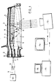
- FIG. 1 there is shown in section a hollow blade 1 of a model X, air-cooled and comprising a foot 2 and a hollow blade 3.
- the blade comprises an upstream channel 4 at in the vicinity of its leading edge, the cold air supply of which is effected by the foot 2 while the air is evacuated by 53 micro-holes 5 made on the upper surface in the vicinity of the leading edge.
- the blade also includes a downstream cavity 6 fed by two channels 7 of the blade root 2 and internally comprising pins or bridges 8 of turbulence.
- the air is evacuated towards the trailing edge by two rows of microperforations 9 of approximately 500 microns in diameter, each row comprising 80 and 19 holes respectively.
- the general principle of the invention consists in illuminating such a hollow vane from the inside and in watching and analyzing the light radiation which passes through the wall of the vane through the orifices 3 or 9, the number and characteristics of which must be measured.
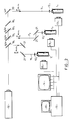
- the dawn is illuminated by means of a coherent light source, here a laser tube 10 of the ionized argon type, with a power of 1 Watt, with continuous emission which produces a light beam with a wavelength of 514.4 nanometers.
- a coherent light source here a laser tube 10 of the ionized argon type, with a power of 1 Watt, with continuous emission which produces a light beam with a wavelength of 514.4 nanometers.
- the image received by the camera 13 is sent to a video monitor 14 on which it can be interpreted by an operator.
- the beam 11 is focused by means of a converging lens 12 and its optical axis is oriented substantially in the axis of symmetry of the cavity to be illuminated, here the downstream cavity 6.
- said blade is positioned relative to the laser source 10 so as to favor a uniform light distribution in the cavity of the blade.
- the "n metal " refraction indices of said metals vary from 0.58 to 0.63 and the absorption coefficient is zero.
- the efficiency ⁇ is equal to 0.057 for reflection.
- said nickel base alloy called DS 200 (trade name) comprising 12% W, 10% Co, 9% Cr, 5% Al, remains Ni, the yield ⁇ is equal to 0.076.
- the signals from the camera 13 are sent to a digital analog computer where they are digitized to be processed in an image processing module 15.
- image processing module 15 By processing convolutions and filtering, the detection sensitivity is improved and the contrast between the subsequent perforations and the rest of the part is increased. Corrected images are thus recreated which can be viewed on the screen 16 linked to the processing module 15.
- the image being stored it is possible for each scan of the image to establish the luminance curve relating to the corresponding section of the room.
- the light intensity received point by point and digitized is a function of the diameter of the micro-hole through which the corresponding light ray is taken out. So we can make a more detailed analysis of the exact state of the part. Examples of implementation will now be explained with reference to FIGS. 4 to 7.
- the two types of hollow blades have been checked by means of the device according to the invention.
- the two types of blades were high pressure turbine engine turbine blades, the first, model X, in INCONEL 718 and the second, model Y in DS 200.
- the number of existing microperforations is summarized in the following table:
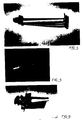
- Figure 4 is a photo of the dawn of model X which we see the holes of the trailing edge.
- FIG. 5 is the photo of the optical signature of the holes on the trailing edge as visible on the video screen 14. It can be seen that all of the holes are reproduced on the photo in FIG. 5. The two rows of holes are visible and the number of holes in each row can be counted.
- FIG. 6 is the photo of the leading edge of the dawn of the model Y.
- the processed and digitally reconstructed image shows two of the three rows of 25 existing holes. The orientation of the third row of holes does not make it visible in the photo.
- the 15th hole corresponds to section AA in Figure 7.
- Exploitation of the luminance curve of this section shows two peaks of intensity.
- the first peak 17a of high height, corresponds to an orifice of normal diameter 18a.
- the second peak 17b of lower height reveals the existence of an orifice 18b that the video image did not reveal.
- a more detailed analysis of the orifice 18b showed that the latter opened obliquely and that the diameter "visible" by the camera was 0.15 mm instead of the 0.50 expected. Such a defect in the geometry of the hole would not have been visible with the previous method of rod inspection.
- each light intensity peak can be compared with a predetermined binarization threshold, which allows a qualitative and quantitative analysis of counting through microperforations.
- Figures 11a to 11d are the digitized images of the trailing edge photographed in Figure 10a.
- Figure 11a we can see that between the 4th and 5th holes visible from the top row from the right, a black gap longer than the others shows a hole not opening on the bottom row, the 5th hole from the right is slightly through. This qualitative analysis can be quantified and the geometric parameters of the microperforations can be determined.
- FIG. 15 represents a portion of the display screen of the image processing module 15
- the screen is separated into pixels of dimension "e".
- Line scanning allows each pixel to be assigned the binarized level of light intensity corresponding to a hole or an undrilled part of the surface.
- By counting consecutive illuminated pixels one can know the surface of each micro-hole and one can determine the center of gravity of each micro-hole which one assimilates to the geometric center of the hole.
- a second processing method makes it possible to refine the parameters which have just been mentioned.
- FIG. 13 represents the binarized image of a double row of holes of the trailing edge of a blade of a model Z, as obtained by the methods described above while FIG. 14 is the representation of it under form of "image skeleton" obtained in the following manner.
- the photo in Figure 14 is the reconstruction by this method of the outline of each hole in Figure 13, each point of each outline having been determined by the method indicated above.
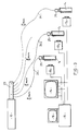
- each laser beam 11 i is sent to a part to be checked 1 i before which it is focused by a lens 12 i .
- the radiation reflection principle is identical to that seen above, the device comprises n cameras 13 i in parallel and the image processing module 15 comprises n parallel memories and a processing unit making it possible to reconstruct n corrected images. controlled parts.
- the detection and calculation means are identical to those of FIG. 2.
- the essential difference lies in the means of transmission of the laser beams used.
- the laser 10 of power P Watts emits radiation on an optical assembly 23 of separation whose outputs consist of n optical fibers 24 i at the end of which are arranged means of focusing 25 of the beam, adapted to said optical fibers.
- the device can also be automated to improve the control rate by adding to it a device for gripping parts and a robot for placing the parts in front of each control position, and for turning the parts, for those whose holes on the edge of the The attack and the trailing edge must be checked, or alternatively by leaving the part stationary and using a robot carrying the image collection camera.
- the proposed method greatly improves the quality and speed of the control and it makes it possible to control holes whose diameter can go down to 10 microns, value below which the light beam which was parallel to the entry of the hole to control would be diffracted as it passed through the hole, making the method inapplicable.
Landscapes
- Physics & Mathematics (AREA)
- Mechanical Engineering (AREA)
- General Physics & Mathematics (AREA)
- Engineering & Computer Science (AREA)
- Analytical Chemistry (AREA)
- Immunology (AREA)
- Life Sciences & Earth Sciences (AREA)
- Chemical & Material Sciences (AREA)
- Optics & Photonics (AREA)
- Biochemistry (AREA)
- General Health & Medical Sciences (AREA)
- Health & Medical Sciences (AREA)
- Pathology (AREA)
- Length Measuring Devices By Optical Means (AREA)
- Investigating Materials By The Use Of Optical Means Adapted For Particular Applications (AREA)
- Closed-Circuit Television Systems (AREA)
- Image Processing (AREA)
- Electrical Discharge Machining, Electrochemical Machining, And Combined Machining (AREA)
- Turbine Rotor Nozzle Sealing (AREA)
Claims (3)
dadurch gekennzeichnet,
daß die Analyse der Signale eine Binärumwandlung umfaßt und die durch die Videokamera (13) gesehene Oberfläche in Pixel bekannter Abmessungen unterteilt ist,
Applications Claiming Priority (2)
| Application Number | Priority Date | Filing Date | Title |
|---|---|---|---|
| FR8812008A FR2636423B1 (fr) | 1988-09-15 | 1988-09-15 | Controle optique de micropercages d'aubes de turbine |
| FR8812008 | 1988-09-15 |
Publications (2)
| Publication Number | Publication Date |
|---|---|
| EP0359660A1 EP0359660A1 (de) | 1990-03-21 |
| EP0359660B1 true EP0359660B1 (de) | 1992-06-17 |
Family
ID=9369995
Family Applications (1)
| Application Number | Title | Priority Date | Filing Date |
|---|---|---|---|
| EP89402495A Expired - Lifetime EP0359660B1 (de) | 1988-09-15 | 1989-09-13 | Optische Kontrolle von Mikrobohrungen einer Turbinenschaufel |
Country Status (6)
| Country | Link |
|---|---|
| US (1) | US5054087A (de) |
| EP (1) | EP0359660B1 (de) |
| JP (1) | JPH0648174B2 (de) |
| DE (1) | DE68901839T2 (de) |
| ES (1) | ES2033539T3 (de) |
| FR (1) | FR2636423B1 (de) |
Families Citing this family (37)
| Publication number | Priority date | Publication date | Assignee | Title |
|---|---|---|---|---|
| GB2287092A (en) * | 1994-03-04 | 1995-09-06 | Vernon Gauging Systems Limited | Monitoring nozzle holes |
| US5773790A (en) * | 1997-01-21 | 1998-06-30 | General Electric Company | Beam blocking material and method for beam drilling and inspecting cooling holes |
| DE19702851C1 (de) * | 1997-01-27 | 1998-08-06 | Deutsch Zentr Luft & Raumfahrt | Verfahren und Vorrichtung zur Prüfung offener, aber nicht vollständig einsehbarer Hohlräume |
| GB9707372D0 (en) * | 1997-04-11 | 1997-05-28 | Bpb Plc | Cementitiuos tile |
| US6909800B2 (en) * | 2000-12-15 | 2005-06-21 | United Technologies Corporation | Process and apparatus for locating coated cooling holes on turbine vanes |
| EP1416266B1 (de) * | 2002-11-04 | 2006-09-27 | Siemens Aktiengesellschaft | Verfahren zur Überprüfung der Struktur von Durchgangslöchern eines Bauteils |
| US7333218B2 (en) * | 2005-06-28 | 2008-02-19 | United Technologies Corporation | Systems and methods for determining the location and angular orientation of a hole with an obstructed opening residing on a surface of an article |
| US20060291716A1 (en) * | 2005-06-28 | 2006-12-28 | Janakiraman Vaidyanathan | Thermal imaging and laser scanning systems and methods for determining the location and angular orientation of a hole with an obstructed opening residing on a surface of an article |
| US7388204B2 (en) * | 2005-12-07 | 2008-06-17 | Meyer Tool, Inc. | Apparatus and method for analyzing relative outward flow characterizations of fabricated features |
| US7671338B2 (en) * | 2006-06-14 | 2010-03-02 | Meyer Tool, Inc. | Apparatus and method for analyzing relative outward flow characterizations of fabricated features |
| GB0809037D0 (en) | 2008-05-19 | 2008-06-25 | Renishaw Plc | Video Probe |
| US20100030365A1 (en) * | 2008-07-30 | 2010-02-04 | Pratt & Whitney | Combined matching and inspection process in machining of fan case rub strips |
| US8977528B2 (en) | 2009-04-27 | 2015-03-10 | The Boeing Company | Bonded rework simulation tool |
| US9108738B1 (en) | 2009-05-19 | 2015-08-18 | The Boeing Company | Apparatus for refueling aircraft |
| US8568545B2 (en) | 2009-06-16 | 2013-10-29 | The Boeing Company | Automated material removal in composite structures |
| US8524020B2 (en) | 2009-06-16 | 2013-09-03 | The Boeing Company | Method of restoring a composite airframe |
| GB0914904D0 (en) * | 2009-08-27 | 2009-09-30 | Rolls Royce Plc | Inspection of holes |
| US20110080588A1 (en) * | 2009-10-02 | 2011-04-07 | Industrial Optical Measurement Systems | Non-contact laser inspection system |
| EP2386823A1 (de) * | 2010-05-12 | 2011-11-16 | Siemens Aktiengesellschaft | Oberflächenanalyse zur Detektierung verschlossener Löcher und Verfahren zur Wiedereröffnung |
| EP2386824A1 (de) * | 2010-05-12 | 2011-11-16 | Siemens Aktiengesellschaft | Oberflächenanalyse zur Detektierung veschlossener Löcher und Verfahren zur Wiederöffnung |
| GB2487931A (en) * | 2011-02-09 | 2012-08-15 | Rolls Royce Plc | Inspection of an engine component |
| EP2581563A1 (de) | 2011-10-13 | 2013-04-17 | Siemens Aktiengesellschaft | Vorrichtung und Verfahren zur Durchgangsmessung |
| JP5682551B2 (ja) * | 2011-12-27 | 2015-03-11 | 株式会社デンソー | 孔加工物品の検査装置及び検査方法 |
| JP5845985B2 (ja) * | 2012-03-13 | 2016-01-20 | 大同特殊鋼株式会社 | 羽根車の欠陥検査方法 |
| US9134232B1 (en) | 2012-11-15 | 2015-09-15 | Industrial Optical Measurement Systems, LLC | Laser inspection system |
| US9581556B1 (en) | 2012-11-15 | 2017-02-28 | Industrial Optical Measurement Systems, LLC | Laser probe for use in an inspection system |
| JP2017508151A (ja) * | 2014-02-24 | 2017-03-23 | レニショウ パブリック リミテッド カンパニーRenishaw Public Limited Company | 視覚プローブを使用して物体を検査する方法 |
| US10295475B2 (en) | 2014-09-05 | 2019-05-21 | Rolls-Royce Corporation | Inspection of machined holes |
| DE102015206984B4 (de) * | 2015-04-17 | 2019-05-09 | Fraunhofer-Gesellschaft zur Förderung der angewandten Forschung e.V. | Verfahren und Vorrichtung zur optischen Kontrolle von Kühlluftausnehmungen von Turbomaschinen |
| US10228669B2 (en) | 2015-05-27 | 2019-03-12 | Rolls-Royce Corporation | Machine tool monitoring |
| CN105758321B (zh) * | 2016-05-04 | 2018-04-10 | 安徽工业大学 | 火车车轮轮毂内孔直径激光测量系统及其测量方法 |
| GB2565079A (en) * | 2017-07-31 | 2019-02-06 | Erodex Uk Ltd | Inspection system and method for turbine vanes and blades |
| CN108818015B (zh) * | 2018-07-05 | 2020-06-02 | 广州德力数控设备有限公司 | 一种定位夹具及其精度检测工艺 |
| CN111982029A (zh) * | 2020-07-27 | 2020-11-24 | 华东师范大学 | 一种涡轮叶片气膜孔空间方位角误差测量方法 |
| CN112304625B (zh) * | 2020-10-21 | 2022-07-15 | 江苏江航智飞机发动机部件研究院有限公司 | 一种用于飞机发动机涡轮叶片的检测装置 |
| CN113693269A (zh) * | 2021-07-15 | 2021-11-26 | 红云红河烟草(集团)有限责任公司 | 一种在线烟支综合质量检测装置 |
| CN113731830B (zh) * | 2021-07-15 | 2023-05-23 | 红云红河烟草(集团)有限责任公司 | 一种激光打孔中空滤嘴检测装置 |
Family Cites Families (10)
| Publication number | Priority date | Publication date | Assignee | Title |
|---|---|---|---|---|
| US343656A (en) * | 1886-06-15 | Half to william l | ||
| US3495915A (en) * | 1966-06-27 | 1970-02-17 | Gen Electric | Photoelectric probe detecting and measuring apparatus |
| US3680966A (en) * | 1971-03-12 | 1972-08-01 | Iris Corp | Apparatus and method for shell inspection |
| US4484081A (en) * | 1980-09-19 | 1984-11-20 | Trw Inc. | Defect analysis system |
| JPS59159004A (ja) * | 1983-03-01 | 1984-09-08 | N C Sangyo Kk | 孔径測定装置 |
| US4555798A (en) * | 1983-06-20 | 1985-11-26 | Kla Instruments Corporation | Automatic system and method for inspecting hole quality |
| US4783751A (en) * | 1983-08-17 | 1988-11-08 | University Of South Carolina | Analysis of pore complexes |
| US4803639A (en) * | 1986-02-25 | 1989-02-07 | General Electric Company | X-ray inspection system |
| EP0254200A1 (de) * | 1986-07-18 | 1988-01-27 | Siemens Aktiengesellschaft | Verfahren zum Prüfen auf fehlerhafte durchkontaktierte Bohrungen bei gedruckten Leiterplatten |
| US4901361A (en) * | 1988-05-27 | 1990-02-13 | The United States Of America As Represented By The Secretary Of The Air Force | Automated spall panel analyzer |
-
1988
- 1988-09-15 FR FR8812008A patent/FR2636423B1/fr not_active Expired - Lifetime
-
1989
- 1989-09-13 JP JP1238344A patent/JPH0648174B2/ja not_active Expired - Fee Related
- 1989-09-13 EP EP89402495A patent/EP0359660B1/de not_active Expired - Lifetime
- 1989-09-13 DE DE8989402495T patent/DE68901839T2/de not_active Expired - Fee Related
- 1989-09-13 ES ES198989402495T patent/ES2033539T3/es not_active Expired - Lifetime
- 1989-09-15 US US07/407,584 patent/US5054087A/en not_active Expired - Lifetime
Also Published As
| Publication number | Publication date |
|---|---|
| DE68901839D1 (de) | 1992-07-23 |
| JPH03170005A (ja) | 1991-07-23 |
| US5054087A (en) | 1991-10-01 |
| FR2636423A1 (fr) | 1990-03-16 |
| JPH0648174B2 (ja) | 1994-06-22 |
| DE68901839T2 (de) | 1993-02-04 |
| EP0359660A1 (de) | 1990-03-21 |
| FR2636423B1 (fr) | 1990-11-30 |
| ES2033539T3 (es) | 1993-03-16 |
Similar Documents
| Publication | Publication Date | Title |
|---|---|---|
| EP0359660B1 (de) | Optische Kontrolle von Mikrobohrungen einer Turbinenschaufel | |
| EP3701222B1 (de) | Verfahren und vorrichtung zur messung von abmessungen durch röntgenstrahlen auf in einer linie verlaufenden leeren glasbehältern | |
| EP0970367B1 (de) | Verfahren zur kontrolle der oberfläche einer laufenden materialbahn mit bildsegmentierung zur umgrenzung von defektbereichen | |
| EP1296797B1 (de) | Verfahren zur feststellung, lokalisierung und identifizierung von fehlerstellen in einer schweissnaht mit einem laserstrahl | |
| EP0620051B1 (de) | Verfahren und Vorrichtung zur automatischen Sortierung von Produkten, hauptsächlich von Früchten oder Gemüsen | |
| FR3036800A1 (fr) | Procede d’observation d’un echantillon | |
| FR2659039A1 (fr) | Procede et appareil de surveillance optique du traitement des materiaux par laser. | |
| CA2880145C (fr) | Procede de controle non destructif d'une preforme d'aube | |
| FR2984531A1 (fr) | Microscopie optique non-lineaire quantitative utilisant un faisceau mis en forme | |
| EP0970368B1 (de) | Verfahren zur kontrolle der oberfläche einer laufenden materialbahn mit vorklassifikation von ermittelten unregelmässigkeiten | |
| CA2643371A1 (fr) | Biodetecteur sans contact | |
| EP0993650B1 (de) | Verfahren zur segmentierung und erkennung eines beleges, insbesondere einer technischen zeichnung | |
| EP0329224B1 (de) | Längenmessverfahren mit einer photosensitiven Zeilenkamera | |
| CA3154503A1 (fr) | Procede d'evaluation de la stabilite d'un film lacrymal | |
| FR3105528A1 (fr) | Procédé de détection de défauts d’un élément en matériau composite | |
| JP4490061B2 (ja) | 粒子画像分析装置 | |
| FR2911081A1 (fr) | Installation et procede de detection optique des deteriorations d'une buse laser | |
| WO2024061843A1 (fr) | Microscope optique avec résonateur | |
| FR2770296A1 (fr) | Procede d'analyse de particules atmospheriques et appareil d'analyse de particules atmospheriques pour la mise en oeuvre d'un tel procede | |
| FR2707008A1 (en) | Method for inspecting a weld bead, in particular on a motor-vehicle suspension sphere and device for implementing this method | |
| WO1998044338A1 (fr) | Procede d'inspection de surface d'une bande en defilement et d'analyse de la defectuosite de la bande | |
| EP4419881A1 (de) | Verfahren zur herstellung eines werkzeugs zur funktionellen charakterisierung während der herstellung oder nach der herstellung eines optischen objektivs | |
| JP3124221B2 (ja) | ヘッドシリンダの閉塞検査装置 | |
| FR3128627A1 (fr) | Systèmes et procédés de caractérisation d’une région d’intérêt d’un tissu biologique | |
| FR2658601A1 (fr) | Procede et appareillage de controle de la forme de surface par la methode du moire d'ombre. |
Legal Events
| Date | Code | Title | Description |
|---|---|---|---|
| PUAI | Public reference made under article 153(3) epc to a published international application that has entered the european phase |
Free format text: ORIGINAL CODE: 0009012 |
|
| 17P | Request for examination filed |
Effective date: 19891002 |
|
| AK | Designated contracting states |
Kind code of ref document: A1 Designated state(s): DE ES FR GB IT |
|
| 17Q | First examination report despatched |
Effective date: 19910523 |
|
| GRAA | (expected) grant |
Free format text: ORIGINAL CODE: 0009210 |
|
| AK | Designated contracting states |
Kind code of ref document: B1 Designated state(s): DE ES FR GB IT |
|
| ITF | It: translation for a ep patent filed | ||
| REF | Corresponds to: |
Ref document number: 68901839 Country of ref document: DE Date of ref document: 19920723 |
|
| GBT | Gb: translation of ep patent filed (gb section 77(6)(a)/1977) | ||
| REG | Reference to a national code |
Ref country code: ES Ref legal event code: FG2A Ref document number: 2033539 Country of ref document: ES Kind code of ref document: T3 |
|
| PLBE | No opposition filed within time limit |
Free format text: ORIGINAL CODE: 0009261 |
|
| STAA | Information on the status of an ep patent application or granted ep patent |
Free format text: STATUS: NO OPPOSITION FILED WITHIN TIME LIMIT |
|
| 26N | No opposition filed | ||
| REG | Reference to a national code |
Ref country code: GB Ref legal event code: IF02 |
|
| REG | Reference to a national code |
Ref country code: FR Ref legal event code: TP Ref country code: FR Ref legal event code: CD |
|
| PGFP | Annual fee paid to national office [announced via postgrant information from national office to epo] |
Ref country code: GB Payment date: 20040826 Year of fee payment: 16 Ref country code: DE Payment date: 20040826 Year of fee payment: 16 |
|
| PGFP | Annual fee paid to national office [announced via postgrant information from national office to epo] |
Ref country code: FR Payment date: 20040827 Year of fee payment: 16 |
|
| PGFP | Annual fee paid to national office [announced via postgrant information from national office to epo] |
Ref country code: ES Payment date: 20040915 Year of fee payment: 16 |
|
| PG25 | Lapsed in a contracting state [announced via postgrant information from national office to epo] |
Ref country code: IT Free format text: LAPSE BECAUSE OF NON-PAYMENT OF DUE FEES;WARNING: LAPSES OF ITALIAN PATENTS WITH EFFECTIVE DATE BEFORE 2007 MAY HAVE OCCURRED AT ANY TIME BEFORE 2007. THE CORRECT EFFECTIVE DATE MAY BE DIFFERENT FROM THE ONE RECORDED. Effective date: 20050913 Ref country code: GB Free format text: LAPSE BECAUSE OF NON-PAYMENT OF DUE FEES Effective date: 20050913 |
|
| PG25 | Lapsed in a contracting state [announced via postgrant information from national office to epo] |
Ref country code: ES Free format text: LAPSE BECAUSE OF NON-PAYMENT OF DUE FEES Effective date: 20050914 |
|
| PG25 | Lapsed in a contracting state [announced via postgrant information from national office to epo] |
Ref country code: DE Free format text: LAPSE BECAUSE OF NON-PAYMENT OF DUE FEES Effective date: 20060401 |
|
| GBPC | Gb: european patent ceased through non-payment of renewal fee |
Effective date: 20050913 |
|
| PG25 | Lapsed in a contracting state [announced via postgrant information from national office to epo] |
Ref country code: FR Free format text: LAPSE BECAUSE OF NON-PAYMENT OF DUE FEES Effective date: 20060531 |
|
| REG | Reference to a national code |
Ref country code: FR Ref legal event code: ST Effective date: 20060531 |
|
| REG | Reference to a national code |
Ref country code: ES Ref legal event code: FD2A Effective date: 20050914 |