EP0359596A1 - Datenübertragungseinrichtung zur leichten und beschleunigten Herstellung von Brillengläsern - Google Patents
Datenübertragungseinrichtung zur leichten und beschleunigten Herstellung von Brillengläsern Download PDFInfo
- Publication number
- EP0359596A1 EP0359596A1 EP89401912A EP89401912A EP0359596A1 EP 0359596 A1 EP0359596 A1 EP 0359596A1 EP 89401912 A EP89401912 A EP 89401912A EP 89401912 A EP89401912 A EP 89401912A EP 0359596 A1 EP0359596 A1 EP 0359596A1
- Authority
- EP
- European Patent Office
- Prior art keywords
- card
- bus
- data
- connector
- microprocessor
- Prior art date
- Legal status (The legal status is an assumption and is not a legal conclusion. Google has not performed a legal analysis and makes no representation as to the accuracy of the status listed.)
- Withdrawn
Links
Images

Classifications
-
- G—PHYSICS
- G05—CONTROLLING; REGULATING
- G05B—CONTROL OR REGULATING SYSTEMS IN GENERAL; FUNCTIONAL ELEMENTS OF SUCH SYSTEMS; MONITORING OR TESTING ARRANGEMENTS FOR SUCH SYSTEMS OR ELEMENTS
- G05B19/00—Program-control systems
- G05B19/02—Program-control systems electric
- G05B19/418—Total factory control, i.e. centrally controlling a plurality of machines, e.g. direct or distributed numerical control [DNC], flexible manufacturing systems [FMS], integrated manufacturing systems [IMS] or computer integrated manufacturing [CIM]
- G05B19/41845—Total factory control, i.e. centrally controlling a plurality of machines, e.g. direct or distributed numerical control [DNC], flexible manufacturing systems [FMS], integrated manufacturing systems [IMS] or computer integrated manufacturing [CIM] characterised by system universality, reconfigurability, modularity
-
- G—PHYSICS
- G05—CONTROLLING; REGULATING
- G05B—CONTROL OR REGULATING SYSTEMS IN GENERAL; FUNCTIONAL ELEMENTS OF SUCH SYSTEMS; MONITORING OR TESTING ARRANGEMENTS FOR SUCH SYSTEMS OR ELEMENTS
- G05B19/00—Program-control systems
- G05B19/02—Program-control systems electric
- G05B19/418—Total factory control, i.e. centrally controlling a plurality of machines, e.g. direct or distributed numerical control [DNC], flexible manufacturing systems [FMS], integrated manufacturing systems [IMS] or computer integrated manufacturing [CIM]
- G05B19/4185—Total factory control, i.e. centrally controlling a plurality of machines, e.g. direct or distributed numerical control [DNC], flexible manufacturing systems [FMS], integrated manufacturing systems [IMS] or computer integrated manufacturing [CIM] characterised by the network communication
-
- Y—GENERAL TAGGING OF NEW TECHNOLOGICAL DEVELOPMENTS; GENERAL TAGGING OF CROSS-SECTIONAL TECHNOLOGIES SPANNING OVER SEVERAL SECTIONS OF THE IPC; TECHNICAL SUBJECTS COVERED BY FORMER USPC CROSS-REFERENCE ART COLLECTIONS [XRACs] AND DIGESTS
- Y02—TECHNOLOGIES OR APPLICATIONS FOR MITIGATION OR ADAPTATION AGAINST CLIMATE CHANGE
- Y02P—CLIMATE CHANGE MITIGATION TECHNOLOGIES IN THE PRODUCTION OR PROCESSING OF GOODS
- Y02P90/00—Enabling technologies with a potential contribution to greenhouse gas [GHG] emissions mitigation
- Y02P90/02—Total factory control, e.g. smart factories, flexible manufacturing systems [FMS] or integrated manufacturing systems [IMS]
Definitions
- the present invention relates generally to the machining of ophthalmic lenses and more particularly to an installation intended to facilitate and accelerate the supply of finished spectacles to users.
- the latter when a customer has chosen a frame from an optician, the latter must first measure the position of the client's pupils relative to the chosen frame and then, if he has the appropriate lenses in stock, center them on the frame according to the identified position of the pupils, and finally cut them out in a grinding machine, if it has one.
- the optician does not have the glasses in stock, which is the most frequent case, he must order them from a supplier and if in addition he does not have a grinding machine he must transmit to the supplier all the measures necessary for cut the lenses and center them and mount them properly on the frame.
- the object of the invention is to provide an installation having a great flexibility of operation and making it possible to considerably speed up the supply of the finished glasses by eliminating almost any risk. errors.
- FR-2,582,975 in the name of the applicant describes an apparatus comprising electronic means and which makes it possible to integrate the measurements of the deviation and the height of the pupils, previously taken for example by means of the apparatus described in FR- A-2.620.927 by the applicant, to center the glass blanks on the frames by calculating the grinding dimensions and to center and place an adapter on the blank.
- This device associated with a copious of frames is marketed under the brand "SCANFORM" and is able to directly order a grinder.
- the invention aims to produce an installation comprising a working set to which an optician can directly address and associating Scanform devices and grinders with a data transmission network.
- a computer is connected to said module forming a master assembly, itself connected by a point-to-point data transmission line and bidirectional to said slave modules.
- said first and the other devices for centering blanks and for fitting adapters are of the type described in FR-2,582,975.
- said first set is a device marketed by the applicant under the brand "Scanform”.
- an optician can either send to said installation, by post or otherwise, a handwritten note comprising the data necessary for the identification of the chosen frame, at the height and away from the pupils, and to the prescription corrective lenses, or send the same data via a telephone data transmission line if it has one, for example connected to a personal management computer, as is more and more common.
- the data is entered manually into the module forming the master assembly by an operator who uses this assembly to perform the centering operations, one of the slave groups receiving the dimensions calculated by said assembly and consequently controlling its associated grinder.
- the orders and the data which are part of them are received and managed by said computer and transmitted one after the other to the module forming the master assembly, and the operator performs the remaining necessary operations.
- each of the master / slave modules contains a first electronic card by carrying out the piloting and the control and to which are connected a second electronic card forming communication and archiving processor and a third electronic card regulating the supply of electrical energy to the entire module.
- the second card forming a communication and archiving processor contains an internal bus connecting a microprocessor controlling the exchanges between the first card and the external systems, to different electronic signal / data processing circuits, via a bus interface carrying out the adaptation and demultiplexing of the microprocessor signals, and a synchronization interface connecting the microprocessor to the first card.
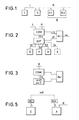
- FIG. 1 which shows the general arrangement of an installation in accordance with the invention
- the latter essentially comprises a master apparatus or module A forming a master assembly (which is unique and is imperatively provided), apparatuses or slave modules B1, B2, ... (multiple and optional, also designated below in the text generally by the reference B), and a computer C (single and optional).
- the devices B are connected to the device A by a data transmission channel R with multipoint structures, while the devices A and C are connected by a data transmission channel L with point-to-point structure.
- the devices A and B have the same architecture, as shown in more detail in FIG. 2, their operation being differentiated by means of particular electrical signals present in the line R connecting the various devices A and B to the network.
- the devices A and B are made up of different mechanical elements which, depending on the specificity of the use of the device, are present in part or in whole, as can be seen in FIG. 2, these different elements are: an input mechanism S, making it possible to read the internal shape of a spectacle frame and transform it into a series of electrical signals S1; a mechanism V for viewing this shape and for depositing a suction cup for gripping a raw glass according to a specific coded geometric reference as well as the shape by means of a series of electrical signals S2, a mechanism which includes a keyboard with keys allowing the optician to give orders or translated information subsequently in electrical signals and associated with the other signals S2; a mechanism M for grinding the raw glass, making it possible to give the latter a profile identical to the shape described, by means of electrical signals S3.
- an input mechanism S making it possible to read the internal shape of a spectacle frame and transform it into a series of electrical signals S1
- a mechanism V for viewing this shape and for depositing a suction cup for gripping a raw glass according
- This AUT card is itself connected to a second electronic COM card, called the communication and archiving processor, by means of an electrical signal transmission channel S4, and it is on this card that the R and L channels for data transmission.
- the assembly is completed by a third electronic card ALI, called the power supply card, which makes it possible to supply the electrical energies Ui necessary for the other sub-assemblies from the sector.
- ALI the power supply card
- the installation according to the invention makes it possible to transmit between the various devices for opticians all their service data and all the data specific to each patient and necessary for the work carried out on these appliances.
- the link is controlled by only one of these devices which is the logical master of the link between all the devices and ensures the link with the management microcomputer and ensures the management of the archives.
- a computer can be connected directly to the network, in which case control can then be attributed to another device.
- the devices are connected to a serial, multipoint and bidirectional transmission line, operated in half-duplex.
- the master appliance A may not include mechanisms such as those described above, its architecture then being reduced to that shown in FIG. 3.
- the AUT PLC card can even be replaced by a simple computer having its own storage, processing and calculation devices, and possibly operator dialogs. In the case of this configuration, it will be noted that the device C is then deleted.
- the device C is a computer having its own storage, processing, calculation and operator dialogue devices (keyboard and CRT for example), and is also connected by an interface to channel L of data transmission.
- the combination of these devices A, B, C automates all the operations of an optician in his pharmacy or in a laboratory, from the reception of a patient with the taking into account of his prescription until on the issue of a pair of fitted glasses.
- Figure 4 represents the card forming the COM communications processor, which is the basis of the specific operation of the device A for the intended treatment.
- This card provides the communication protocol in the installation as well as the management of files and is generally carried out by the so-called HC MOS technology.
- This card includes various connectors for connection with external elements and internal circuits.
- Connector 1 transmits according to a transmission bidirectional a set of signals arriving from the bidirectional signal transmission channel R.
- the connector 2 transmits a set of electrical signals, comprising levels conforming to recommendation V24 of the CCITT Committee, establishes bidirectional links for transmission of electrical signals, having the levels conforming to recommendation V24 / V28 of the CCITT Committee, and is connected to device C, which is a computer or, as we will see later, is possibly a modem.
- the connector 3 joins the COM card to the AUT card in a bidirectional connection, for the transmission of signals previously designated by S4.
- the connector 4 delivers the energy necessary for the operation of the COM card receiving supply signals Ui coming from the ALI card.
- the COM card includes a microprocessor 5 (for example of the type known under the acronym 80C88, namely of the 16-bit type with data transmission bus with 8 bits)
- This microprocessor is connected in particular to a backup memory CMOS RAM saved 6 to 256 k.bytes and ROM ROM 7 to 128 k.bytes via a general signal and data bus 9, which is connected to all the components of the circuit, and by means of a bus link interface 10.
- the microprocessor is controlled by a clock controlled by quartz.
- a synchronization interface 11 is connected in a bidirectional connection to the microprocessor 5 and to the connector 3 as well as to the bus 9.
- the connector 3 and the bus 9 are also connected to an exchange RAM memory 12 via a multiplexer 13.
- Two clocks 14 and 15 are further connected to bus 9 and each respectively in a one-way connection to a respective universal synchronous / asynchronous transmitter / receiver 16 and 17 also connected to bus 9.
- the transmitter / receiver 17 is connected to connector 2 by via a unidirectional input link by means of the adapter 18 and via a unidirectional link by means of the adapter 19.
- the transmitter / receiver 16 is connected to a mixer 23 by means of an output isolation device 20 and by means of an input isolation device 21, the mixer being connected to a device isolated switching power supply 22.
- the mixer is connected in a bidirectional connection to connector 1.
- bus 9 is connected to the connector 1 via an address transmission interface 24.
- Connector 1 delivers a set of signals arriving from the data transmission channel R:
- the first address signals are transmitted directly by the read interface 24 to the microprocessor 5 via the bus 9 and the interface of the internal bus 10; thanks to the program stored in the microprocessor's memory, the latter ensures master operation, corresponding to device A, or slave operation, corresponding to one of devices B (B1, B2, ...); these signals allow) to distinguish one of the devices B; the other signals relate to the exchange of data between the devices and will be described later.
- connector 2 transmits a set of electrical signals between the card and device C.
- One of these signals, after its adaptation at 18 is transmitted to the microprocessor 5 by the circuits 17 and 10 to indicate the presence of a device C and governs in consequently the operation of master device A.
- the device C In the case of the normal configuration, the device C is present and therefore the optician records, from the keyboard and the screen of this device, all the data relating to a patient and in particular those contained in his prescription.
- the latter analyzes them and sends itself other control and synchronization signals to the computer, signals which are transmitted by the interface 10, by the circuit 17 and by the circuit 19, which shape them, to connector 2.
- the microprocessor 5 stores all the data received from the computer in its own memory 6 and on the other hand sends all this data to the slave devices B.
- the microprocessor 5 transcodes this data in the form of signals electrics transmitted by the interface 10 to the circuit 16, which itself transmits them by means of the isolation device 20, the mixer circuit 23 and the connector 1, to all the devices B connected to the same data transmission channel R .
- All the connectors B then receive, at their connector 1, these signals which reach the microprocessor 5 via the circuits 23, 21, 16 and 10.
- the microprocessors 5 of the devices B which recognize their operation in slave mode as described above, decode the signals and store all the corresponding data arriving from the computer C via the master device A, in its memory 6.
- one or more opticians work on devices A or B; from the various mechanisms S, V, M or other mechanisms K, they communicate orders transmitted in the form of electrical signals S1, S2, S3 or Si and interpreted by the automat cards AUT.
- the first information required is the identification of the patient to whom the optician's work relates.
- the signals coding this identification are transmitted by the automat card AUT to the communication card COM of the device concerned, via the connector 3, are stored in the memory RAM 12, which remains in communication with the PLC card by the intermediate multiplexer 13 and connector 3; the microprocessor 5 is then activated by one of the signals via the synchronization interface 11 and positions the multiplexer 13 to be put in communication with the RAM exchange memory 12.
- the microprocessor 5 can search the data relating to the patient by comparing on the one hand signals coding the identification of the patient in the memory 12, described by the card AUT, and on the other hand signals coding the identifications of all the patients in memory 6.
- the microprocessor 5 introduces the data (negative report or patient data) coded into electrical signals in the memory 12, again places the multiplexer 13 in the rest position and notifies the AUT card thereof by synchronization signals, via the interface 11 of the connector 3.
- the microprocessor 5 of the device A presents the request of the optician to the device C by coding the identification of the patient into electrical signals sent to the computer by means of the circuits 10, 17, 19 and connector 2.
- the computer After its own search, the computer sends then by the same device as that described above the necessary data (negative report or patient data); the microprocessor 5 decodes the signals received from the computer, stores them in its memory 6 and sends them to all the slave devices B as indicated above.
- the microprocessor 5 of the devices B transmits the request from the optician to the master device A by coding the identification of the patient into electrical signals sent to the device A by means of the circuits 10, 16, 20 and 23 of connector 1.
- Device A then receives its patient identification signals requested by its connector 1 and its circuits 23, 21, 16 and 10, and the microprocessor 5 of device A searches for patient data by means of a type comparison. indicated above; if the search results in a negative result, the request is retransmitted towards the computer C which gives its answer as indicated above; Finally, the microprocessor 5 of device A, which has found or received from the computer the necessary data (negative report or patient data), rebroadcast them to all devices B which receive the signals and, after processing , store them in their own memories 6, as indicated above.
- the data are used and possibly modified by the AUT card.
- the microprocessor 5 analyzes the order of the optician transmitted in the memory 12 and performs the following operations: - it updates the electrical signals encoding the patient's data in its own memory 6 and in particular it can completely erase this data; - if it is a master device A, it transforms these signals to send them to the slave devices B, via circuits 10, 7, 20 and 23 and connector 1, as indicated above; - if it is a slave device B, it transforms these signals to communicate them to the master device A, via circuits 10, 16, 20 and 23 of connector 1. Device A receives then these signals via its connector 1 and its circuits 23, 21, 16 and 10.
- the microprocessor 5 of the device performs the same operation as that which it would have performed if the same data had been communicated to it by its AUT card, i.e. it updates the patient data in its own memory 6 and transmits it to all the slave devices B via the network R.
- the optician can resume or continue operations on any device A or B.
- the computer C can consult the master device A to know the content of the patient data managed by the installation and in particular after a prolonged stop of its own operation.
- the latter then analyzes the request from the computer by exploiting or modifying the patient data coded as electrical signals in its memory 6; then it gives a report or a response to computer C by means of a series of electrical signals returned via circuits 10, 17, 19 and connector 2.
- certain signals coding them designate a particular installation, identified by a string of characters or numbers and stored in the AUT card; if these signals are not recognized by the microprocessor 5 of the COM card of the device A after comparison with the stored signals, the subsequent operation of the system can be modified or even entirely blocked, which thus protects the confidential nature of all or part information about an unauthorized third-party computer.
- the microprocessor 5 of the device A broadcasts the request from the computer to the slave devices B by means of the network R as indicated above. Each device B then stores the patient data coded as electrical signals in its own memory.
- the operation described above between the devices A and C in direct connection via the data transmission channel L can occur when the devices A and C are located at a distance from each other and are then connected to the same data transmission channel L, but by means of MA and MC modems as shown in FIG. 5. It will be noted that the role of these modems is simply to adapt the electrical nature of the signals exchanged to allow their transmission over a long distance via a specific medium designated by MP.
- the master device A may not include any mechanical device or optics specific to an optician's laboratory operation and, in this case, the AUT card of this device is equivalent to a simple computer with circuits for calculation, processing, storage and operator dialogues (keyboard, screens, etc.) .) and can even replace device C, which then becomes useless.
- the master device A is carried out from a computer including the COM communication card as described above, or that some of the functions of the COM card are directly executed by the computer itself. even, in which case this device would be directly connected by interface to the network R, with a transmission of signals identical to those presented by the connector 1 of a COM card.
- the operation of the installation can be summarized as follows.
- the operation of the latter is mainly governed by the COM communication card represented in FIG. 4, which is connected to a bidirectional multipoint bus R, to a local computer C or to a decentralized computer MA (modem) and to the PLC card AUT , the power supplies being provided by the connector 4.
- the microprocessor 5 controls the exchanges between the AUT card and the external computer and network elements and manages the protocols specific to the applications related to the operations of the optician stores the patient data in its saved memory 6 programmed by its read-only memory 7 and controlled in clocked fashion by its control clock 8 controlled by quartz.
- the internal bus 9 carries all the information necessary for the various circuits and the interface 10 for linking the bus adapts and demultiplexes the signals from the microprocessor.
- the synchronization interface 11 provides the arbîtrage between the automat card AUT and the microprocessor 5 to obtain access to the memory 12, which allows mass transfer of information from one to the other, the multiplexer 13 ensuring access to this memory.
- Programmable clocks 14 and 15 control the transmission speeds of the two serial links managed by universal synchronous / asynchronous transmitters / receivers 16 and 17.
- Adapters 18 and 19 transform the electrical levels of the internal logic into V24 / V28 levels compatible with computers and modems.
- the isolation devices 20 and 21 galvanically isolate and adapt the internal logic to the network R using the isolated switching power supply device 22.
- the mixture 23 ensures the joining of the input / output signals on the two information transmission wires of the network R.
Landscapes
- Engineering & Computer Science (AREA)
- General Engineering & Computer Science (AREA)
- Manufacturing & Machinery (AREA)
- Quality & Reliability (AREA)
- Physics & Mathematics (AREA)
- General Physics & Mathematics (AREA)
- Automation & Control Theory (AREA)
- Medical Treatment And Welfare Office Work (AREA)
Applications Claiming Priority (2)
| Application Number | Priority Date | Filing Date | Title |
|---|---|---|---|
| FR8811731A FR2636143B1 (fr) | 1988-09-08 | 1988-09-08 | Installation de transmission de donnees, destinee a faciliter et accelerer la fabrication de verres de lunettes |
| FR8811731 | 1988-09-08 |
Publications (1)
| Publication Number | Publication Date |
|---|---|
| EP0359596A1 true EP0359596A1 (de) | 1990-03-21 |
Family
ID=9369815
Family Applications (1)
| Application Number | Title | Priority Date | Filing Date |
|---|---|---|---|
| EP89401912A Withdrawn EP0359596A1 (de) | 1988-09-08 | 1989-07-04 | Datenübertragungseinrichtung zur leichten und beschleunigten Herstellung von Brillengläsern |
Country Status (2)
| Country | Link |
|---|---|
| EP (1) | EP0359596A1 (de) |
| FR (1) | FR2636143B1 (de) |
Cited By (5)
| Publication number | Priority date | Publication date | Assignee | Title |
|---|---|---|---|---|
| WO1993013911A1 (de) * | 1992-01-13 | 1993-07-22 | Wernicke & Co. Gmbh | Vorrichtung zum facettieren von brillengläsern |
| US9208608B2 (en) | 2012-05-23 | 2015-12-08 | Glasses.Com, Inc. | Systems and methods for feature tracking |
| US9236024B2 (en) | 2011-12-06 | 2016-01-12 | Glasses.Com Inc. | Systems and methods for obtaining a pupillary distance measurement using a mobile computing device |
| US9286715B2 (en) | 2012-05-23 | 2016-03-15 | Glasses.Com Inc. | Systems and methods for adjusting a virtual try-on |
| US9483853B2 (en) | 2012-05-23 | 2016-11-01 | Glasses.Com Inc. | Systems and methods to display rendered images |
Citations (2)
| Publication number | Priority date | Publication date | Assignee | Title |
|---|---|---|---|---|
| US4027246A (en) * | 1976-03-26 | 1977-05-31 | International Business Machines Corporation | Automated integrated circuit manufacturing system |
| EP0206860A1 (de) * | 1985-06-10 | 1986-12-30 | Briot International | Vorrichtung zum Zentrieren und Auflegen eines Adapters auf einen Rohling eines optischen Glases sowie zum Steuern einer Schleifmaschine |
-
1988
- 1988-09-08 FR FR8811731A patent/FR2636143B1/fr not_active Expired - Fee Related
-
1989
- 1989-07-04 EP EP89401912A patent/EP0359596A1/de not_active Withdrawn
Patent Citations (2)
| Publication number | Priority date | Publication date | Assignee | Title |
|---|---|---|---|---|
| US4027246A (en) * | 1976-03-26 | 1977-05-31 | International Business Machines Corporation | Automated integrated circuit manufacturing system |
| EP0206860A1 (de) * | 1985-06-10 | 1986-12-30 | Briot International | Vorrichtung zum Zentrieren und Auflegen eines Adapters auf einen Rohling eines optischen Glases sowie zum Steuern einer Schleifmaschine |
Non-Patent Citations (1)
| Title |
|---|
| TECHNISCHE RUNDSCHAU vol. 79, no. 49, 4 décembre 1987, BERN,SCHWEIZ pages 96 - 101; PAWELLEK ET HARTMUT: "MONTAGELEITSYSTEME FÜR KUNDENAUFTRAGSORIENTIERTE JUST-IN-TIME PRODUKTION" * |
Cited By (9)
| Publication number | Priority date | Publication date | Assignee | Title |
|---|---|---|---|---|
| WO1993013911A1 (de) * | 1992-01-13 | 1993-07-22 | Wernicke & Co. Gmbh | Vorrichtung zum facettieren von brillengläsern |
| US9236024B2 (en) | 2011-12-06 | 2016-01-12 | Glasses.Com Inc. | Systems and methods for obtaining a pupillary distance measurement using a mobile computing device |
| US9208608B2 (en) | 2012-05-23 | 2015-12-08 | Glasses.Com, Inc. | Systems and methods for feature tracking |
| US9235929B2 (en) | 2012-05-23 | 2016-01-12 | Glasses.Com Inc. | Systems and methods for efficiently processing virtual 3-D data |
| US9286715B2 (en) | 2012-05-23 | 2016-03-15 | Glasses.Com Inc. | Systems and methods for adjusting a virtual try-on |
| US9311746B2 (en) | 2012-05-23 | 2016-04-12 | Glasses.Com Inc. | Systems and methods for generating a 3-D model of a virtual try-on product |
| US9378584B2 (en) | 2012-05-23 | 2016-06-28 | Glasses.Com Inc. | Systems and methods for rendering virtual try-on products |
| US9483853B2 (en) | 2012-05-23 | 2016-11-01 | Glasses.Com Inc. | Systems and methods to display rendered images |
| US10147233B2 (en) | 2012-05-23 | 2018-12-04 | Glasses.Com Inc. | Systems and methods for generating a 3-D model of a user for a virtual try-on product |
Also Published As
| Publication number | Publication date |
|---|---|
| FR2636143A1 (fr) | 1990-03-09 |
| FR2636143B1 (fr) | 1990-11-02 |
Similar Documents
| Publication | Publication Date | Title |
|---|---|---|
| WO2000028489A1 (fr) | Systeme de personnalisation de cartes a puce | |
| EP0511140A1 (de) | Datenaustauschsystem zwischen einem elektronischen Objekt das zu einer Übertragungseinrichtung für unterschiedliche geschwindigkeiten angeschlossen ist und Einrichtung dafür | |
| FR2651352A2 (fr) | Circuit d'interfacage pour recepteur d'informations radiodiffusees de guidage pour automobilistes. | |
| EP0394114A1 (de) | Multifunktionskoppler zwischen einer zentralen Verarbeitungseinheit eines Rechners und verschiedenen Peripheriegeräten dieses Rechners | |
| EP0359596A1 (de) | Datenübertragungseinrichtung zur leichten und beschleunigten Herstellung von Brillengläsern | |
| FR2822009A1 (fr) | Systeme et procede pour fournir un support client | |
| EP0752669A1 (de) | Vorrichtung zur Datenübertragung zwischen einer Mehrzahl von Funktionsmodulen in einer lokalen Buseinheit und einem externen RINC-629-Bus | |
| FR2493562A1 (fr) | Systeme d'utilisation de disques en commun et d'intercommunication entre disques | |
| CN101852921B (zh) | 立体眼镜系统及其设置识别码的方法 | |
| EP0011701A1 (de) | Auswahlsystem für Vorrangsschnittstellen und Datenübertragungssteuereinrichtung mit solchem Auswahlsystem | |
| FR2650412A1 (fr) | Dispositif passerelle de connexion d'un bus d'ordinateur a un reseau fibre optique en forme d'anneau | |
| FR2785122A1 (fr) | Procede et dispositif de pilotage a distance d'un automate et carte prevue a cet effet | |
| WO1997006621A1 (fr) | Procede de communication sur un bus optique a cohabitation de debits differents | |
| CH632350A5 (en) | Data processing assembly | |
| EP1358748A2 (de) | Vorrichtung und verfahren zur automatischen sicheren paarbildung zwischen geräten eines funkfrequenznetzes | |
| WO2005015873A1 (fr) | Procédé de détection automatique de protocole de transmission pour objet portable de type carte à puce ou clé à puce | |
| EP0615370A1 (de) | Netzwerkübertragungssystem | |
| EP0561699B1 (de) | Kommunikationsverfahren für eine programmierbare industrielle Steuerung und Schnittstelle für die Ausführung des Verfahrens | |
| WO2003055267A1 (fr) | Interface et procede d'affectation de connexions haut debit | |
| FR2775407A1 (fr) | Poste telephonique avec reconnaissance de parole, et systeme de commande vocale comportant un tel poste | |
| WO2018211179A1 (fr) | Procede pour la creation de comptes d'acces au reseau internet | |
| EP2282262A1 (de) | Kommunikationsgerät, Verfahren zur Kommunikation zwischen besagtem Gerät und einem Netzwerk, Schnittstelleneinheit zwischen besagtem Gerät und besagtem Netzwerk | |
| WO2001047317A1 (fr) | Circuit d'interface isdn - usb | |
| EP1422867A1 (de) | System und Verfahren zum Internetzugang | |
| CN102438156A (zh) | 具有自动搜寻通讯协议的3d影像系统及自动搜寻的方法 |
Legal Events
| Date | Code | Title | Description |
|---|---|---|---|
| PUAI | Public reference made under article 153(3) epc to a published international application that has entered the european phase |
Free format text: ORIGINAL CODE: 0009012 |
|
| 17P | Request for examination filed |
Effective date: 19890727 |
|
| AK | Designated contracting states |
Kind code of ref document: A1 Designated state(s): DE ES GB |
|
| RAP1 | Party data changed (applicant data changed or rights of an application transferred) |
Owner name: BRIOT INTERNATIONAL |
|
| 17Q | First examination report despatched |
Effective date: 19920629 |
|
| STAA | Information on the status of an ep patent application or granted ep patent |
Free format text: STATUS: THE APPLICATION IS DEEMED TO BE WITHDRAWN |
|
| 18D | Application deemed to be withdrawn |
Effective date: 19921110 |