EP0359003B1 - Process for transforming solid, substantially anhydrous waste materials into glass, and apparatus therefor - Google Patents
Process for transforming solid, substantially anhydrous waste materials into glass, and apparatus therefor Download PDFInfo
- Publication number
- EP0359003B1 EP0359003B1 EP89115675A EP89115675A EP0359003B1 EP 0359003 B1 EP0359003 B1 EP 0359003B1 EP 89115675 A EP89115675 A EP 89115675A EP 89115675 A EP89115675 A EP 89115675A EP 0359003 B1 EP0359003 B1 EP 0359003B1
- Authority
- EP
- European Patent Office
- Prior art keywords
- gas
- glass
- exhaust gas
- glass batch
- melting
- Prior art date
- Legal status (The legal status is an assumption and is not a legal conclusion. Google has not performed a legal analysis and makes no representation as to the accuracy of the status listed.)
- Expired - Lifetime
Links
Images


Classifications
-
- C—CHEMISTRY; METALLURGY
- C03—GLASS; MINERAL OR SLAG WOOL
- C03B—MANUFACTURE, SHAPING, OR SUPPLEMENTARY PROCESSES
- C03B3/00—Charging the melting furnaces
- C03B3/02—Charging the melting furnaces combined with preheating, premelting or pretreating the glass-making ingredients, pellets or cullet
- C03B3/023—Preheating
-
- B—PERFORMING OPERATIONS; TRANSPORTING
- B09—DISPOSAL OF SOLID WASTE; RECLAMATION OF CONTAMINATED SOIL
- B09B—DISPOSAL OF SOLID WASTE
- B09B3/00—Destroying solid waste or transforming solid waste into something useful or harmless
- B09B3/20—Agglomeration, binding or encapsulation of solid waste
- B09B3/25—Agglomeration, binding or encapsulation of solid waste using mineral binders or matrix
- B09B3/29—Agglomeration, binding or encapsulation of solid waste using mineral binders or matrix involving a melting or softening step
-
- C—CHEMISTRY; METALLURGY
- C03—GLASS; MINERAL OR SLAG WOOL
- C03B—MANUFACTURE, SHAPING, OR SUPPLEMENTARY PROCESSES
- C03B19/00—Other methods of shaping glass
- C03B19/10—Forming beads
- C03B19/109—Glass-melting furnaces specially adapted for making beads
-
- C—CHEMISTRY; METALLURGY
- C03—GLASS; MINERAL OR SLAG WOOL
- C03B—MANUFACTURE, SHAPING, OR SUPPLEMENTARY PROCESSES
- C03B5/00—Melting in furnaces; Furnaces so far as specially adapted for glass manufacture
- C03B5/005—Melting in furnaces; Furnaces so far as specially adapted for glass manufacture of glass-forming waste materials
-
- C—CHEMISTRY; METALLURGY
- C03—GLASS; MINERAL OR SLAG WOOL
- C03B—MANUFACTURE, SHAPING, OR SUPPLEMENTARY PROCESSES
- C03B5/00—Melting in furnaces; Furnaces so far as specially adapted for glass manufacture
- C03B5/02—Melting in furnaces; Furnaces so far as specially adapted for glass manufacture in electric furnaces, e.g. by dielectric heating
- C03B5/027—Melting in furnaces; Furnaces so far as specially adapted for glass manufacture in electric furnaces, e.g. by dielectric heating by passing an electric current between electrodes immersed in the glass bath, i.e. by direct resistance heating
- C03B5/03—Tank furnaces
-
- C—CHEMISTRY; METALLURGY
- C03—GLASS; MINERAL OR SLAG WOOL
- C03B—MANUFACTURE, SHAPING, OR SUPPLEMENTARY PROCESSES
- C03B5/00—Melting in furnaces; Furnaces so far as specially adapted for glass manufacture
- C03B5/04—Melting in furnaces; Furnaces so far as specially adapted for glass manufacture in tank furnaces
-
- C—CHEMISTRY; METALLURGY
- C03—GLASS; MINERAL OR SLAG WOOL
- C03B—MANUFACTURE, SHAPING, OR SUPPLEMENTARY PROCESSES
- C03B5/00—Melting in furnaces; Furnaces so far as specially adapted for glass manufacture
- C03B5/16—Special features of the melting process; Auxiliary means specially adapted for glass-melting furnaces
- C03B5/235—Heating the glass
-
- F—MECHANICAL ENGINEERING; LIGHTING; HEATING; WEAPONS; BLASTING
- F01—MACHINES OR ENGINES IN GENERAL; ENGINE PLANTS IN GENERAL; STEAM ENGINES
- F01N—GAS-FLOW SILENCERS OR EXHAUST APPARATUS FOR MACHINES OR ENGINES IN GENERAL; GAS-FLOW SILENCERS OR EXHAUST APPARATUS FOR INTERNAL COMBUSTION ENGINES
- F01N2550/00—Monitoring or diagnosing the deterioration of exhaust systems
-
- Y—GENERAL TAGGING OF NEW TECHNOLOGICAL DEVELOPMENTS; GENERAL TAGGING OF CROSS-SECTIONAL TECHNOLOGIES SPANNING OVER SEVERAL SECTIONS OF THE IPC; TECHNICAL SUBJECTS COVERED BY FORMER USPC CROSS-REFERENCE ART COLLECTIONS [XRACs] AND DIGESTS
- Y02—TECHNOLOGIES OR APPLICATIONS FOR MITIGATION OR ADAPTATION AGAINST CLIMATE CHANGE
- Y02P—CLIMATE CHANGE MITIGATION TECHNOLOGIES IN THE PRODUCTION OR PROCESSING OF GOODS
- Y02P40/00—Technologies relating to the processing of minerals
- Y02P40/50—Glass production, e.g. reusing waste heat during processing or shaping
Definitions
- the invention relates to a method for transferring solid, largely water-free waste materials in glass form, waste incineration ash being used as the waste material.
- the invention relates to a device for performing the method.
- waste incineration ash into glass form A difficulty in converting waste incineration ash into glass form is that such waste materials generally contain a high proportion of chlorides and calcium sulfate, which are only absorbed to a small extent by the glass melt during the melting process, even if the glass melt's ability to absorb chlorides and sulfur is used up to the saturation limit, since the batch to be melted contains a corresponding amount.
- heavy metals are absorbed into the glass to a sufficient extent, but it is disadvantageous that the resulting exhaust gases nevertheless contain heavy metals and additional alkali components which escape from the glass melt by evaporation.
- a melting furnace for the melting or vitrification of non-radioactive, dangerous substances is also known, in which a liquid mixture is introduced into the furnace. Liquid from the downstream gas scrubber for the escaping gas is also introduced into the glass melting furnace, but there is no possibility for the treatment and preheating of solid components, such as waste incineration ash.
- waste incineration ash a waste material that was previously considered to be very problematic, namely waste incineration ash, can be converted into glass in an environmentally friendly manner, although such ashes are composed very heterogeneously with high and fluctuating proportions, in particular of carbon, mercury, lead, tin, zinc, calcium, chlorides and halides are.
- a large part of the pollutants from the incineration ash goes directly into the glass melt and is thus firmly integrated. Pollutants escaping in gaseous form are largely condensed by cooling within the batch to be melted and returned to the melt access. The remaining, only relatively small amount of cold exhaust gases are made harmless in the final gas cleaning.
- a further development of the method provides that the hot exhaust gas emerging from the melting mixture is reheated for a time of at least 1.5 s to a temperature of at least 1200 ° C., then precooled to a temperature between 200 to 300 ° C. with partial condensation , then returned to the batch to be melted and cooled there to 20 to 50 ° C. with further condensation, and that the condensation products obtained during the pre-cooling are returned to the batch to be melted and / or drawn off.
- the reheating of the exhaust gas is destroyed in any dioxins and / or furans that may be present, the minimum temperature and residence time of course being chosen such that they are certainly sufficient for the desired destruction.
- the hot exhaust gas drawn off thereafter essentially contains only chlorides, sulfates, carbon dioxide and alkali and heavy metal vapors.
- This hot exhaust gas is partially condensed in the following pre-cooling to 200 - 300 ° C and thus reduced in its quantity and the number of its ingredients.
- the condensation products obtained are kept in a closed circuit by the intended return into the batch to be melted and gradually transferred into the glass, an equilibrium state being reached after a running-in phase in which the amount of the condensation products remains essentially constant.
- vapors such as heavy metal vapors and in particular mercury vapor, which condense only at low temperatures, accumulate on the batch particles and are thus returned to the melting process.
- Gas cleaning requires only a relatively small capacity and also provides comparatively pure separation products, in particular sodium chloride and sodium sulfate, which, for. B. can be used for the production of soda.
- the heat energy required for the melting is preferably generated electrically, since this avoids the addition of combustion gases from heating burners operated with fossil fuels to the exhaust gas originating from the melting mixture, which complicates the subsequent exhaust gas treatment.
- the new process is both environmentally compatible and economical, because on the one hand it largely reduces the emission of exhaust gas and on the other hand it provides usable raw materials, namely vitreous bodies which, for. B. can be used as a building material or building material surcharge, and the sodium chloride and sulfate mentioned. An emission of dioxins and / or furans is excluded in the further development of the new process.
- An embodiment of this development provides that the hot exhaust gas is reheated in a separate reheater.
- This process variant is not so cheap in terms of energy balance, but can be carried out with relatively little effort with regard to the melting device and also offers the advantage that the entire glass bath can be covered with batches, so that a large part of the alkali and heavy metal vapors are already in the Batch blanket condensed in the melting furnace.
- An alternative, particularly energy-efficient embodiment of the method provides that the glass melt is kept free of batches on part of its surface and that the hot exhaust gas after it emerges from the melting one The batch is passed over the batch-free part of the surface of the glass melt and is reheated by absorbing heat from the glass melt.
- Another alternative of the method provides that the cold exhaust gas emerging from the mixture to be melted is reheated for a time of at least 1.5 s to a temperature of at least 1200 ° C. and is then fed to the pollutant gas cleaning process.
- the cold exhaust gas emerging from the mixture to be melted is reheated for a time of at least 1.5 s to a temperature of at least 1200 ° C. and is then fed to the pollutant gas cleaning process.
- dioxins and / or furans cannot get into the environment but are destroyed by appropriate heating of the exhaust gas.
- the method provides that the exhaust gas emerging from the pollutant gas cleaning process is reheated to a temperature of at least 1200 ° C. for at least 1.5 s. This also achieves the desired destruction of dioxins and / or furans.
- the choice of the method variant to be used is at the discretion of the person skilled in the art and is based on the requirements and circumstances of the individual case.
- a liquid alkali salt or alkaline earth salt bile layer is generated on the part of the surface of the glass melt covered with batch and is kept in a layer thickness range between 2 and 5 cm by means of deduction if necessary .
- some of the pollutants emerging from the melting mixture are incorporated into the bile layer, so that the exhaust gas is correspondingly less polluted.
- the alkali salt bile which has been stripped off and enriched with pollutants, may, after cooling and solidification, have B. be fed back to the process, wherein the pollutants from the bile layer gradually pass into the glass melt.
- a bile layer consisting essentially of sodium sulfate or chloride or potassium sulfate or chloride or lithium sulfate or chloride or a mixture of these is used and that this bile layer during the melting process by reaction from calcium sulfate, calcium chloride, Magnesium sulfate and / or magnesium chloride is generated, which is fed to the melting process with the waste incineration ash and / or as a separate additive to the batch.
- the method provides that SiO2-containing substances, in particular sand and / or phonolite, are used. These additives are easy to handle and inexpensive. Alternatively or additionally, broken glass can also be used as an additive containing SiO2.
- the method also provides that the hot exhaust gas emerging from the melting batch and the hot exhaust gas are removed and pre-cooled, that the pre-cooled exhaust gas is pressurized and that the passage of the exhaust gas through the batch to be melted is regulated in countercurrent to it and in such a way takes place that the pressure of the cold exhaust gas emerging from the melt to be melted is substantially equal to the ambient air pressure.
- dust and / or sludge accumulating in gas cleaning can be mixed into the batch.
- the exhaust gas after the gas cleaning is advantageously passed through an activated carbon filter and, in order to simplify the exhaust gas treatment, the exhaust gas can advantageously be cooled before or after the gas cleaning.
- the second part of the object is achieved by a device according to claim 15.
- This device enables a safe, continuous and environmentally compatible implementation of the method described above.
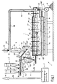
- the first illustrated embodiment of the device 1 essentially consists of the following components: an arrangement of storage containers 2, a batch mixer 3, a glass melting furnace 4, a glass processing machine 5, an exhaust gas cooler 6 and a gas cleaning device 7.
- the storage containers 2 serve to receive and store waste incineration ash 80 on the one hand and additives 81 on the other.
- the storage containers 2 each have a metering lock 20, e.g. B. a rotary valve on.
- These metering locks 20 open into a common conveyor device 21, here a screw conveyor, which opens into the upper part of the batch mixer 3.
- the batch mixer 3 has an essentially funnel-shaped housing 30 which narrows downward, and a mixer screw 31 arranged in this housing 30.
- the mixer screw 31 runs parallel to Inside of the side wall of the housing 30 and can be rotated both about its own axis and about an axis running centrally in the vertical direction through the housing 30 of the batch mixer 3.
- a solids inlet 32 is provided, which is connected to the aforementioned conveyor 21.
- a solids outlet 33 is provided which opens into a batch feed device 46.
- the batch feeder 46 already forms part of the glass melting furnace 4.
- the glass melting furnace 4 consists of a trough 41 made of refractory material, which is covered at the top by a superstructure 42, also made of refractory material.
- the tub 41 and the superstructure 42 rest on a supporting structure 40, which is formed here from steel girders.
- the superstructure 42 of the glass melting furnace 4 is surrounded by a gas-tight jacket 42 ', which consists of sheet steel and which extends to the upper edge of the tub 41 and is sealingly connected to it.
- a gas-tight jacket 42 ' which consists of sheet steel and which extends to the upper edge of the tub 41 and is sealingly connected to it.
- heating electrodes 43 gas-tight into the interior of the glass melting furnace 4.
- the interior of the glass melting furnace 4 is divided into two different areas, namely a melting part that is on the left in FIG. 1 and a heating part that is on the right in FIG. 1.
- the division of the glass melting furnace 4 into the two areas mentioned is carried out by a part of the superstructure 42, which projects downward from this, a sloping arch 44, which is in operation of the glass melting furnace 4 to just above the surface 84 'of one located in the furnace 4 Glass melt 84 is sufficient and forms a vertical partition for the gas space of the furnace 4. Furthermore, a coolant tube 45 is provided below the arc 44 and runs parallel to it through the glass melting furnace 4, which is located exactly at the surface 84 'of the glass melt 84 and serves to solidify the glass melt 84 in the vicinity of the tube 45 bring to. At the right end of the glass melting furnace 4, a glass melt outlet 48 is provided, which is followed by a glass processing machine 5, which is only shown schematically here. Finally, at the right end of the glass melting furnace 4 there is also an exhaust gas discharge opening 47 which runs upwards through the superstructure 42.
- a heat-insulated gas line 60 which leads to the gas inlet 61 of the exhaust gas cooler 6, is connected to the exhaust gas discharge opening 47 of the glass melting furnace 4.
- the exhaust gas cooler 6 has a gas outlet 62 and an outlet 63 for condensation products, the gas outlet 62 and outlet 63 being arranged at the lower end of the exhaust gas cooler 6.
- the exhaust gas cooler 6 has means 65 for guiding and for supplying and removing a coolant, e.g. B. cooling water or cooling air.
- a mechanical cleaning device 66 is indicated above the exhaust gas cooler 6, by means of which the exhaust gas-carrying parts of the exhaust gas cooler 6 can be cleaned continuously or periodically from the condensation products obtained there as a result of the exhaust gas cooling.
- the associated outlet 63 of the exhaust gas cooler 6 for the condensation products is via a further conveyor 64, here also a screw conveyor, with the feed side of the batch mixer 3, i. H. the upper part of its interior.
- the upper part of the housing 30 of the batch mixer 3 has an opening which represents an inlet 36 for the condensation products.
- a switch 69 at the upper end of the conveying device 64 the condensation products can, if necessary, be partially or completely discharged.
- a first suction fan 67 Downstream of the gas outlet 62 of the exhaust gas cooler 6 is a first suction fan 67, which is connected on the outlet side to a connecting line 68.
- This connecting line 68 leads to a gas inlet 34 of the batch mixer 3, wherein the gas inlet 34 is arranged in the lower part of the housing 30 and is designed in such a way that gas can enter the interior of the housing 30, but an escape of mixtures from the interior of the housing 30 into the line 68 is excluded .
- a gas outlet 35 is provided, which is followed by a second suction fan 70.
- the output of the first suction fan 67 and the second suction fan 70 can be regulated, for which purpose they are preferably connected to a common control device.
- a gas line 71 leads to the gas cleaning device 7, which can be constructed with components known per se and which is therefore not described in detail here.
- a chimney 79 is connected downstream of the gas cleaning device 7.
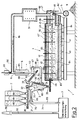
- the embodiment of the device shown in FIG. 2 corresponds in its essential parts to the embodiment previously described with reference to FIG. 1.
- the glass melting furnace 4 is designed somewhat differently.
- the arc 44 present in the glass melting furnace 4 in the exemplary embodiment described first has been eliminated in the glass melting furnace 4 according to FIG. 2, ie the superstructure 42 of the glass melting furnace 4 is designed as a continuous component with a one-piece furnace interior.
- the coolant tube 45 in the glass melting furnace according to FIG. 2 is displaced towards the outlet end of the glass melting furnace 4, ie to the right in FIG. 2.
- the batch 83 floating on the glass melt 84 in the interior of the glass melting furnace 4 can spread over almost the entire surface of the glass melt 84 in the glass melting furnace 4.
- a separate gas heater 91 is inserted into the gas line 60 downstream of the gas exhaust opening 47.
- This gas heater 91 is only indicated schematically in FIG. 2 and can be of a type known per se. In it, the incoming exhaust gas is heated to a temperature of at least 1200 ° C. for at least 1.5 s.
- the further structure of the device according to FIG. 2 corresponds to the structure of the device according to FIG. 1, the same parts of the devices being designated with the same reference numbers.
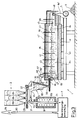
- the third exemplary embodiment of the device according to FIG. 3 is particularly characterized in that the exhaust gas cooler 6 with the associated gas line 60 is not present here.
- the glass melting furnace 4 corresponds essentially to the glass melting furnace, as shown in Figure 2, with the difference that here a gas discharge opening 47 'is provided at the end of the task, ie at the left end of the glass melting furnace 4.
- This gas discharge opening 47 ' is connected via a short gas line 60' to the suction side of the first suction fan 67. From there, the connection line 68 already described leads to the batch mixer 3.
- this batch mixer 3 is formed in its upper part without the feed opening 36 present in the devices described above.
- the last illustrated variant of the device according to FIG. 4 largely corresponds to the exemplary embodiment according to FIG. 3, the difference here being that the separate gas heater 91 for heating the exhaust gas and destroying any dioxins and / or furans present in the gas cleaning device 7 is subordinate and is installed in the gas line leading to the chimney 79.
- This design of the device offers the particular advantage that the amount of gas to be heated behind the gas cleaning device 7 is only about 50% of the original amount of gas, i. H. heating energy is saved.
- the first storage container 2 is fed from a waste incineration plant or from a landfill.
- the further storage containers 2 are filled with the necessary additives 81, in particular sand and phonolite, and possibly broken glass.
- waste incineration ash 80 and the additives 81 are removed from the storage containers 2 in predetermined proportions and conveyed into the interior of the container 30 of the batch mixer 3 by means of the conveyor device 21.
- the individual components are mixed by means of the mixer screw 31 to form a homogeneous batch 82 to be melted.
- Finished batch 82 to be melted is conveyed through the solids outlet 33 of the batch mixer 3 into the interior of the glass melting furnace 4 by means of the batch feed device 46.
- the glass melting furnace 4 is filled with glass melt 84 up to a certain height.
- the surface 84 'of the molten glass 84 lies exactly at the level of the coolant tube 45 and just below the arc 44.
- the batch supplied by the batch feeder 46 floats as a melting batch 83 on the glass melt 84 and is distributed over its surface 84 'in the melting part, i. H. in FIG. 1, left part, of the glass melting furnace 4. Since the glass melt 84 is solidified in the vicinity of the coolant tube 45 by means of the coolant flowing through, the melting mixture 83 cannot get into the part of the glass melting furnace beyond the arc 44 and the coolant tube 45.
- the thermal energy required for melting the batch 83 to be melted is generated by means of the heating electrodes 43, which project into the glass melt 84 with their lower part, as Joule energy in the glass melt 84, the glass melt 84 forming the ohmic resistance.
- This exhaust gas 85 enters the right part of the interior of the glass melting furnace 4 through the gap between the underside of the arc 44 and the coolant tube 45.
- the surface 84 'of the glass melt 84 is free of batches.
- the glass melt 84 located in this part of the glass melting furnace 4 has a temperature of approximately 1400 ° C.
- the temperature in the upper part of the glass melting furnace 4 above the melt 84 is accordingly at least about 1300-1350 ° C.
- the superstructure 42 of the glass melting furnace 4 is expediently thermally insulated.
- This hot exhaust gas 86 is drawn off through the heat-insulated line 60, the heat insulation thereof essentially serving to prevent cooling and thus condensation of the hot exhaust gas 86 within the line 60.
- the hot exhaust gas 86 passes through the gas inlet 61 into the exhaust gas cooler 6, where it is cooled to a temperature between 300 and 500 ° C. Part of the exhaust gas condenses and is deposited within the exhaust gas cooler 6.
- the resulting condensation products 88 are removed periodically or continuously by means of the cleaning device 66 and fed to the outlet 63 for the condensation product located below the exhaust gas cooler 6. From there, the condensation products 88 by means of the conveyor 64 through the inlet 36 for the Condensation products led into the interior of the batch mixer 3 and thus returned to the batch 82 to be melted. If required, the condensation products 88 can be discharged in whole or in part via the switch 69.
- the pre-cooled exhaust gas 87 emerging from the exhaust gas cooler through the gas outlet 62 reaches the first suction fan 67.
- the suction fan 67 ensures that the precooled exhaust gas 87 emerging from it receives an overpressure in relation to the ambient air pressure within the connecting line 68 to the batch mixer 3.
- This pre-cooled exhaust gas 87, which is under an overpressure, is passed through the gas inlet 34 into the batch 82 to be melted in the interior of the batch mixer 3. As the exhaust gas 87 flows through, the latter cools to a temperature of about 20-50 ° C.
- the mixer screw 31 ensures, in addition to mixing the individual components of the batch 82 to be melted, that the latter remains loose and gas-permeable. Due to the strong cooling, even low-condensing vapors, such as, for example, condense within the batch 82 to be melted. B. Heavy metal vapors.
- the cold exhaust gas 89 emerging through the gas outlet 35 of the batch mixer 3 then essentially contains only HCl and SO 2.
- the cold exhaust gas 89 essentially a concentrated gas of chlorides and SO2 and SO3, is fed via line 71 to the gas cleaning device 7 and further cleaned there.
- the remaining waste gases 90, in particular N2, CO2 and small amounts of oxygen, still emerging from the gas cleaning device are finally released through the chimney 79 into the environment. A hazard or damage to the environment due to the relatively harmless components forming the residual exhaust gas 90 is excluded.
- the device 1 in addition to the residual exhaust gas 90, the device 1 according to the exemplary embodiment shown supplies glass bodies 9 as a reusable raw material according to the described method, which are produced by the glass processing machine 5 from the escaping glass melt 84 aus in continuous production.
- These glass bodies 9 can be used, for example, as ballast or concrete aggregate.
- the size of the glass melting furnace 4 and thus the volume of the glass melt 84 located in it are expediently chosen to be so large that fluctuations occurring in the composition of the waste incineration ash cannot briefly change the chemism of the molten glass. Changes occurring in the composition of the glass melt 84 can very quickly e.g. B. on the basis of changes in the electrical resistance of the glass melt 84 between the electrodes 43. These measured values can then be used to regulate the mixture of the waste incineration ash 80 and the individual additives 81, in particular an additive with a certain alkali metal glate, e.g. B. phonolite can be used.
- Another way of correcting the composition of the molten glass 84 is to observe the crystallization phenomena in the finished glass product.
- Specific glass compositions in the border area form certain crystals, which can be easily recognized in the finished glass and which indicate whether and to which side the composition of the glass has changed. Accordingly, the amounts of waste incineration ash 80 and aggregates 81 to be mixed can be varied.
- FIG. 5 showing a wet gas cleaning device 7 and FIG. 6 a dry or semi-dry gas cleaning device 7.
- a pH in the acidic range preferably ⁇ 1
- the second scrubber stage 72 'for the SO2 separation is preferably basic with pH values of z. B. 6 - 7.5 operated.
- the discharged amounts of waste water and sludge discharged from the washing stages 72 and 72 'and the droplet separator 73 are expediently fed to a waste water purification system.
- the second exemplary embodiment of the gas cleaning device 7 according to FIG. 2b has, as the first component, a saturator 75, to which the cold exhaust gas 89 is likewise fed via the line 71. After saturation of the exhaust gas in saturator 75, it is fed to a fluidized bed or spray adsorber 76.
- the spray adsorber is preferably charged with NaOH or Ca (OH) 2 in aqueous solution.
- the escaping gas is brought to the optimum temperature for the activated carbon filter stage 78 that follows here in a gas temperature control stage 77.
- the final exhaust gas 90 finally escaping through the chimney 79 into the environment.
- the resulting wastewater and the resulting solids are also a further cleaning device, for. B. sewage treatment plant, or landfill or reuse.
- the gas cleaning devices 7 can be used to recover sodium chloride and sodium sulfate in a relatively pure form. These raw materials can in turn be used for the production e.g. B. of soda can be used.
- the exhaust gas obtained in relatively small amounts is fed to the dust separation either directly or after passing through the batch in a dust separator and then cleaned in a wet cleaning process.
- Exhaust gas is then passed through an activated carbon filter, and the resulting clean gas can then be easily discharged into the atmosphere, since it no longer contains particles or gas components that are harmful to the environment.
- the method according to the invention has several advantages. First, only two materials are removed from the process. Firstly, the material of the glass, which can be used in road construction or in similar applications, and secondly, the glass bile, which is composed of all the salts, the solubility limit of which is exceeded in the glass melt during the glass melting process and the degree of the melted glass.
- the total amount of pollutants discharged from the process is reduced by the substances in gas cleaning and the heavy metals contained therein. Since the solubility limit for the metals and, in a broader sense, for all heavy metals in the glass melt is not reached during the process, all heavy metals are incorporated in the glass in a leach-proof manner by recycling.
Description
Die Erfindung betrifft ein Verfahren zur Überführung von festen, weitgehend wasserfreien Abfallstoffen in Glasform, wobei als Abfallstoff Müllverbrennungsasche verwendet wird.The invention relates to a method for transferring solid, largely water-free waste materials in glass form, waste incineration ash being used as the waste material.
Weiterhin betrifft die Erfindung eine Vorrichtung zur Durchführung des Verfahrens.Furthermore, the invention relates to a device for performing the method.
Es ist seit längerem bekannt, toxische und radioaktive Abfälle in Form von Schlämmen und Suspensionen nach Zugabe von Zuschlagstoffen und Vermischen zu einem Gemenge durch Schmelzen in ein Glas zu überführen, in welches die zuvor frei vorhandenen Schadstoffe fest eingebaut sind. Glas hat dabei die günstige Eigenschaft, sehr schwer auslaugbar zu sein, so daß ein Freisetzen von Schwermetallen oder anderen im Glas enthaltenen Materialien nur in so geringer Form auftreten kann, daß eine Lagerung oder auch Verwendung von Körpern aus einem derartigen Glas ohne weiteres möglich ist.It has long been known to convert toxic and radioactive waste in the form of sludges and suspensions after addition of additives and mixing into a mixture by melting in a glass in which the previously freely available pollutants are permanently installed. Glass has the favorable property of being very difficult to leach out, so that a release of heavy metals or other materials contained in the glass can only occur in such a small form that storage or use of bodies made of such a glass is readily possible.
Eine Schwierigkeit beim Überführen von Müllverbrennungsasche in Glasform besteht darin, daß derartige Abfallstoffe im allgemeinen einen hohen Anteil an Chloriden und Calcium-Sulfat enthalten, welche beim Schmelzvorgang nur in geringem Maße von der Glasschmelze aufgenommen werden, auch wenn die Aufnahmefähigkeit der Glasschmelze für Chloride und Schwefel bis zur Sättigungsgrenze ausgenutzt wird, da das aufzuschmelzende Gemenge entsprechend viel davon enthält. Dies führt nachteilig dazu, daß große Abgasmengen mit aus Chloriden und Sulfaten entstammenden Gasen, insbesondere Cl, HCl, SO₂ und SO₃, anfallen. Im Gegensatz dazu werden Schwermetalle zwar in ausreichendem Umfang in das Glas aufgenommen, jedoch ist es nachteilig, daß die entstehenden Abgase dennoch Schwermetalle sowie zusätzlich Alkalianteile enthalten, die durch Verdampfung aus der Glasschmelze entweichen.A difficulty in converting waste incineration ash into glass form is that such waste materials generally contain a high proportion of chlorides and calcium sulfate, which are only absorbed to a small extent by the glass melt during the melting process, even if the glass melt's ability to absorb chlorides and sulfur is used up to the saturation limit, since the batch to be melted contains a corresponding amount. This disadvantageously leads to that large amounts of exhaust gas with gases originating from chlorides and sulfates, in particular Cl, HCl, SO₂ and SO₃, accrue. In contrast, heavy metals are absorbed into the glass to a sufficient extent, but it is disadvantageous that the resulting exhaust gases nevertheless contain heavy metals and additional alkali components which escape from the glass melt by evaporation.
Aus der DE-C-2 631 220 ist bereits ein elektrisch beheizter Glasschmelzofen für das Einschmelzen bzw. Verglasen von radioaktiven Abfällen bekannt. Nachteilig ist hier aber, daß die durch Unterdurck abgesaugten Gase in bekannter Weise gereinigt, gefiltert oder absorbiert werden sollen, wodurch wiederum radioaktiv verseuchter Abfall anfällt. Das Gemenge für das Glas und das radioaktive Abfallmaterial werden als Schlamm eingegeben, daher ist eine Vorabreinigung der entstehenden Gase nicht möglich und die Energiebilanz dieses Ofens ist für den großtechnischen Einsatz unbefriedigend.From DE-C-2 631 220, an electrically heated glass melting furnace for melting or vitrifying radioactive waste is already known. The disadvantage here, however, is that the gases sucked off under low pressure are to be cleaned, filtered or absorbed in a known manner, which in turn produces radioactive contamination. The batch for the glass and the radioactive waste material are entered as sludge, so it is not possible to pre-clean the resulting gases and the energy balance of this furnace is unsatisfactory for large-scale use.
Aus der US-A-4 666 490 ist weiterhin ein Schmelzofen für das Einschmelzen bzw. Verglasen von nicht radioaktiven, gefährlichen Stoffen bekannt, bei welchem ein flüssiges Gemenge in den Ofen eingegeben wird. Flüssigkeit aus dem nachgeschalteten Gaswäscher für das austretende Gas wird ebenfalls in den Glasschmelzofen eingeführt, eine Möglichkeit für die Behandlung und Vorerhitzung von festen Bestandteilen, wie Müllverbrennungsasche, besteht aber nicht.From US-A-4 666 490 a melting furnace for the melting or vitrification of non-radioactive, dangerous substances is also known, in which a liquid mixture is introduced into the furnace. Liquid from the downstream gas scrubber for the escaping gas is also introduced into the glass melting furnace, but there is no possibility for the treatment and preheating of solid components, such as waste incineration ash.
Aus der US-A-4 652 289 ist weiterhin ein Verfahren zur Reinigung von Gasen aus einem Schmelzofen bekannt, bei dem die Gase durch eine mit Sand gefüllte Kolonne geführt werden. Eine Durchführung durch die einzuschmelzenden Gefahrenstoffe ist nicht vorgesehen, das gleiche gilt für die Zuschlagstoffe, um ein Gemenge zum Erschmelzen von Glas zu erhalten. Wenn die Menge der zu verglasenden Gefahrstoffe und der Zuschlagstoffe erheblich sind, wird die Energiebilanz dieses Ofens ebenfalls unbefriedigend. Die mit Sand gefüllte Kolonne kann weiterhin SO₂ und einige andere Schadstoffe nicht adsorbieren.From US-A-4 652 289 a method for purifying gases from a melting furnace is also known, in which the gases are passed through a column filled with sand. It is not intended that the hazardous substances to be melted should be used; the same applies to the additives in order to obtain a mixture for melting glass. If the amount of too glazing hazardous substances and the aggregates are considerable, the energy balance of this furnace is also unsatisfactory. The column filled with sand can still not adsorb SO₂ and some other pollutants.
Es stellt sich daher die Aufgabe, ein Verfahren der eingangs genannten Art zu schaffen, das eine bessere Umweltverträglichkeit aufweist und das Schwermetalle enthaltenden Abfallstoffen ausschließt und bei welchem die beim Aufschmelzen der Verbrennungsasche entstehenden Stoffe in möglichst geringem Maße oder überhaupt nicht deponiert werden müssen. Weiterhin stellt sich die Aufgabe, eine Vorrichtung zur Durchführung des Verfahrens anzugeben.It is therefore the task of creating a process of the type mentioned at the outset which has better environmental compatibility and heavy metals excludes waste materials and in which the substances formed during the melting of the incineration ash have to be deposited as little as possible or not at all. Furthermore, there is the task of specifying a device for performing the method.
Die Lösung der Aufgabe gelingt erfindungsgemäß durch ein Verfahren gemäß Patentanspruch 1.The object is achieved according to the invention by a method according to claim 1.
Mit dem neuen Verfahren wird ein bisher als sehr problematisch geltender Abfallstoff, nämlich Müllverbrennungsasche auf umweltverträgliche Weise zu Glas umarbeitbar, obwohl derartige Aschen sehr heterogen mit hohen und schwankenden Anteilen insbesondere an Kohlenstoff, Quecksilber, Blei, Zinn, Zink, Calcium, Chloriden und Halogeniden zusammengesetzt sind. Ein großer Teil der Schadstoffe aus der Müllverbrennungsasche geht unmittelbar in die Glasschmelze über und wird somit fest eingebunden. In Gasform entweichende Schadstoffe Herden weitgehend durch die Abkühlung innerhalb des aufzuschmelzenden Gemenges kondensiert und wieder dem Schmelzzugang zugeführt. Die danach verbleibenden, nur noch in relativ geringer Menge anfallenden kalten Abgase werden in der abschließenden Gasreinigung unschädlich gemacht.With the new process, a waste material that was previously considered to be very problematic, namely waste incineration ash, can be converted into glass in an environmentally friendly manner, although such ashes are composed very heterogeneously with high and fluctuating proportions, in particular of carbon, mercury, lead, tin, zinc, calcium, chlorides and halides are. A large part of the pollutants from the incineration ash goes directly into the glass melt and is thus firmly integrated. Pollutants escaping in gaseous form are largely condensed by cooling within the batch to be melted and returned to the melt access. The remaining, only relatively small amount of cold exhaust gases are made harmless in the final gas cleaning.
Eine Weiterbildung des Verfahren sieht vor, daß das aus dem schmelzenden Gemenge austretende heiße Abgas für eine Zeit von wenigstens 1,5 s auf eine Temperatur von wenigstens 1200°C nacherhitzt wird, danach unter teilweiser Kondensation auf eine Temperatur zwischen 200 bis 300°C vorgekühlt, anschließend in das aufzuschmelzende Gemenge zurückgeführt und dort unter weiterer Kondensation auf 20 bis 50°C abgekühlt wird, und daß die bei der Vorkühlung anfallenden Kondensationsprodukte in das aufzuschmelzende Gemenge zurückgeführt und/oder abgezogen werden. Durch das Nacherhitzen des Abgases werden in diesem eventuell vorhandene Dioxine und/oder Furane sicher zerstört, wobei die Mindesttemperatur und -verweilzeit selbstverständlich so gewählt sind, daß diese sicher für die gewünschte Zerstörung ausreichen. Das danach abgezogene heiße Abgas enthält dann im wesentlichen nur noch Chloride, Sulfate, Kohlendioxid sowie Alkali-und Schwermetalldämpfe. Dieses heiße Abgas wird bei der folgenden Vorkühlung auf 200 - 300°C teilweise kondensiert und damit in seiner Menge sowie der Zahl seiner Inhaltsstoffe reduziert. Die anfallenden Kondensationsprodukte werden durch die vorgesehene Rückführung in das aufzuschmelzende Gemenge im geschlossenen Kreislauf gehalten und nach und nach in das Glas überführt, wobei nach einer Einlaufphase ein Gleichgewichtszustand erreicht wird, in welchem die Menge der Kondensationsprodukte im wesentlichen konstant bleibt. Mit der Durchleitung des vorgekühlten Abgases durch das aufzuschmelzende Gemenge wird erreicht, daß auch erst bei niedrigen Temperaturen kondensierende Dämpfe, wie Schwermetall-Dämpfe und insbesondere Quecksilberdampf, sich an den Gemengeteilchen anlagern und so wieder dem Schmelzvorgang zugeführt werden. Aufgrund der starken Abkühlung des Abgases auf seinem Weg durch das Gemenge werden hier Chloride und Sulfate praktisch vollständig auskondensiert. Falls mehr Chloride und Sulfate verdampft werden als anschließend nach der Rückführung der kondensierten Produkte in der Glasschmelze gelöst werden können, tritt eine Anreicherung dieser Stoffe im Gemenge ein. Um dies zu vermeiden, wird zweckmäßig zumindest der überschüssige Teil der bei der Vorkühlung anfallenden Kondensationsprodukte ausgeschleust. Diese Kondensationsprodukte sind im wesentlichen feste Produkte. Das hiernach verbleibende kalte Abgas enthält dann fast ausschließlich noch Chlorwasserstoff (HCl) und Schwefeldioxid (SO₂) in höherer Konzentration. Das Volumen des dann noch verbleibenden kalten Abgases ist dabei, bezogen auf den Durchsatz an Müllverbrennungsasche, relativ klein. Zudem ist die hier vorliegende relativ hohe Konzentration und einfache Zusammensetzung des kalten Abgases von Vorteil für die nachfolgende, abschließende Gasreinigung. Die Gasreinigung erfordert nur eine relativ geringe Kapazität und liefert zudem vergleichsweise reine Abscheidungsprodukte, insbesondere Natriumchlorid und Natriumsulfat, die z. B. für die Herstellung von Soda verwendet werden können. Die für das Aufschmelzen erforderliche Wärmeenergie wird dabei bevorzugt elektrisch erzeugt, da hierdurch eine die spätere Abgasbehandlung erschwerende Beimengung von Verbrennungsgasen aus mit fossilen Brennstoffen betriebenen Heizbrennern in das aus dem schmelzenden Gemenge stammende Abgas vermieden wird.A further development of the method provides that the hot exhaust gas emerging from the melting mixture is reheated for a time of at least 1.5 s to a temperature of at least 1200 ° C., then precooled to a temperature between 200 to 300 ° C. with partial condensation , then returned to the batch to be melted and cooled there to 20 to 50 ° C. with further condensation, and that the condensation products obtained during the pre-cooling are returned to the batch to be melted and / or drawn off. By the reheating of the exhaust gas is destroyed in any dioxins and / or furans that may be present, the minimum temperature and residence time of course being chosen such that they are certainly sufficient for the desired destruction. The hot exhaust gas drawn off thereafter essentially contains only chlorides, sulfates, carbon dioxide and alkali and heavy metal vapors. This hot exhaust gas is partially condensed in the following pre-cooling to 200 - 300 ° C and thus reduced in its quantity and the number of its ingredients. The condensation products obtained are kept in a closed circuit by the intended return into the batch to be melted and gradually transferred into the glass, an equilibrium state being reached after a running-in phase in which the amount of the condensation products remains essentially constant. By passing the precooled exhaust gas through the batch to be melted, vapors such as heavy metal vapors and in particular mercury vapor, which condense only at low temperatures, accumulate on the batch particles and are thus returned to the melting process. Due to the strong cooling of the exhaust gas on its way through the batch, chlorides and sulfates are practically completely condensed out. If more chlorides and sulfates are evaporated than can subsequently be dissolved in the glass melt after the condensed products have been returned, these substances accumulate in the batch. In order to avoid this, at least the excess part of the condensation products obtained during the pre-cooling is expediently removed. These condensation products are essentially solid products. The remaining cold exhaust gas then contains almost exclusively hydrogen chloride (HCl) and sulfur dioxide (SO₂) in higher concentrations. The volume of the cold exhaust gas then remaining is relatively small, based on the throughput of waste incineration ash. It's also here existing relatively high concentration and simple composition of the cold exhaust gas is advantageous for the subsequent, final gas cleaning. Gas cleaning requires only a relatively small capacity and also provides comparatively pure separation products, in particular sodium chloride and sodium sulfate, which, for. B. can be used for the production of soda. The heat energy required for the melting is preferably generated electrically, since this avoids the addition of combustion gases from heating burners operated with fossil fuels to the exhaust gas originating from the melting mixture, which complicates the subsequent exhaust gas treatment.
Das neue Verfahren ist sowohl in einem hohem Maße umweltverträglich als auch wirtschaftlich, da es zum einen den Ausstoß von Abgas weitestgehend vermindert und da es zum anderen verwertbare Rohstoffe liefert, nämlich Glaskörper, die z. B. als Baustoff oder Baustoff-Zuschlag verwendet werden können, und das erwähnte Natrium-Chlorid und -Sulfat. Ein Ausstoß von Dioxinen und/oder Furanen ist bei der Weiterbildung des neuen Verfahrens ausgeschlossen.The new process is both environmentally compatible and economical, because on the one hand it largely reduces the emission of exhaust gas and on the other hand it provides usable raw materials, namely vitreous bodies which, for. B. can be used as a building material or building material surcharge, and the sodium chloride and sulfate mentioned. An emission of dioxins and / or furans is excluded in the further development of the new process.
Eine Ausgestaltung dieser Weiterbildung sieht vor, daß die Nacherhitzung des heißen Abgases in einem separaten Nacherhitzer erfolgt. Diese Verfahrensvariante ist zwar hinsichtlich der Energiebilanz nicht so günstig, ist jedoch mit relativ geringem Aufwand hinsichtlich der Schmelzeinrichtung durchführbar und bietet darüber hinaus den Vorteil, daß das ganze Glasbad mit Gemenge abgedeckt werden kann, sodaß ein großer Teil der Alkali- und Schwermetalldämpfe bereits in der Gemengedecke im Schmelzofen kondensiert.An embodiment of this development provides that the hot exhaust gas is reheated in a separate reheater. This process variant is not so cheap in terms of energy balance, but can be carried out with relatively little effort with regard to the melting device and also offers the advantage that the entire glass bath can be covered with batches, so that a large part of the alkali and heavy metal vapors are already in the Batch blanket condensed in the melting furnace.
Eine alternative, besonders energiegünstige Ausgestaltung des Verfahrens sieht vor, daß die Glasschmelze auf einem Teil ihrer Oberfläche gemengefrei gehalten wird und daß das heiße Abgas nach dem Austreten aus dem schmelzenden Gemenge über den gemengefreien Teil der Oberfläche der Glasschmelze geleitet und durch Wärmeaufnahme aus der Glasschmelze nacherhitzt wird.An alternative, particularly energy-efficient embodiment of the method provides that the glass melt is kept free of batches on part of its surface and that the hot exhaust gas after it emerges from the melting one The batch is passed over the batch-free part of the surface of the glass melt and is reheated by absorbing heat from the glass melt.
Eine weitere Alternative des Verfahrens sieht vor, daß das aus dem aufzuschmelzenden Gemenge austretende kalte Abgas für eine Zeit von wenigstens 1,5 s auf eine Temperatur von wenigstens 1200°C nacherhitzt wird und danach dem Schadgas-Reinigungsverfahren zugeführt wird. Auch hier ist sichergestellt, daß Dioxine und/oder Furane nicht in die Umwelt gelangen können, sondern durch entsprechende Erhitzung des Abgases zerstört werden.Another alternative of the method provides that the cold exhaust gas emerging from the mixture to be melted is reheated for a time of at least 1.5 s to a temperature of at least 1200 ° C. and is then fed to the pollutant gas cleaning process. Here, too, it is ensured that dioxins and / or furans cannot get into the environment but are destroyed by appropriate heating of the exhaust gas.
Als letzte Alternative hinsichtlich der Nacherhitzung der Abgase sieht das Verfahrens schließlich noch vor, daß das aus dem Schadgas-Reinigungsverfahren austretende Abgas für eine Zeit von wenigstens 1,5 s auf eine Temperatur von wenigstens 1200°C nacherhitzt wird. Auch hierdurch wird die gewünschte Zerstörung von Dioxinen und/oder Furanen erreicht. Die Auswahl der jeweils anzuwendenden Verfahrensvariante liegt im Ermessen des Fachmannes und richtet sich nach den Erfordernissen und Gegebenheiten des Einzelfalles.Finally, as a last alternative with regard to the reheating of the exhaust gases, the method provides that the exhaust gas emerging from the pollutant gas cleaning process is reheated to a temperature of at least 1200 ° C. for at least 1.5 s. This also achieves the desired destruction of dioxins and / or furans. The choice of the method variant to be used is at the discretion of the person skilled in the art and is based on the requirements and circumstances of the individual case.
Um den Wärmeübergang aus der Glasschmelze in das aufzuschmelzende Gemenge zu verbessern, ist vorgesehen, daß auf dem mit Gemenge bedeckten Teil der Oberfläche der Glasschmelze eine flüssige Alkalisalz- oder Erdalkalisalz-Galleschicht erzeugt und durch bedarfsweisen Abzug in einem Schichtdickenbereich zwischen 2 und 5 cm gehalten wird. Neben einer Beschleunigung des Schmelzvorganges wird eine Einbindung eines Teils der aus dem schmelzenden Gemenge austretenden Schadstoffe in die Galleschicht erreicht, so daß das Abgas entsprechend weniger belastet wird. Die bedarfsweise abgezogene, mit Schadstoffen angereicherte Alkalisalz-Galle kann nach Abkühlung und Verfestigung z. B. dem Prozeß wieder zugeführt werden, wobei die Schadstoffe aus der Galleschicht nach und nach in die Glasschmelze übergehen.In order to improve the heat transfer from the glass melt into the batch to be melted, it is provided that a liquid alkali salt or alkaline earth salt bile layer is generated on the part of the surface of the glass melt covered with batch and is kept in a layer thickness range between 2 and 5 cm by means of deduction if necessary . In addition to accelerating the melting process, some of the pollutants emerging from the melting mixture are incorporated into the bile layer, so that the exhaust gas is correspondingly less polluted. The alkali salt bile, which has been stripped off and enriched with pollutants, may, after cooling and solidification, have B. be fed back to the process, wherein the pollutants from the bile layer gradually pass into the glass melt.
Bevorzugt ist dabei vorgesehen, daß als Galleschicht eine im wesentlichen aus Natriumsulfat oder -chlorid oder Kaliumsulfat oder -chlorid oder Lithiumsulfat oder -chlorid oder aus einem Gemisch von diesen bestehende Galleschicht verwendet wird und daß diese Galleschicht während des Schmelzvorganges durch Umsetzen aus Kalziumsulfat, Kalziumchlorid, Magnesiumsulfat und/oder Magnesiumchlorid erzeugt wird, welches mit der Müllverbrennungsasche und/oder als gesonderter Zuschlagstoff zum Gemenge dem Schmelzvorgang zugeführt wird. Alternativ sieht das Verfahren vor, daß bei hohen Schmelztemperaturen und/oder bei Alkalimangel eine Kalziumsulft- und/oder Magensiumsulfat-Galleschicht verwendet wird und daß diese Galleschicht unmittelbar aus mit dem Gemenge oder als gesonderter Zuschlagstoff zugegebenem Kalziumsulfat und/oder Magnesiumsulfat erzeugt wird. Die aufzuwendenden Zusatzkosten werden so sehr niedrig gehalten, so daß sie im Verhältnis zu den bei der Abgasreinigung eingesparten Kosten gering sind. Damit wird das Verfahren insgesamt kostengünstiger durchführbar.It is preferably provided that a bile layer consisting essentially of sodium sulfate or chloride or potassium sulfate or chloride or lithium sulfate or chloride or a mixture of these is used and that this bile layer during the melting process by reaction from calcium sulfate, calcium chloride, Magnesium sulfate and / or magnesium chloride is generated, which is fed to the melting process with the waste incineration ash and / or as a separate additive to the batch. Alternatively, the method provides that a calcium sulphate and / or magnesium sulfate bile layer is used at high melting temperatures and / or in the case of alkali deficiency, and that this bile layer is produced directly from calcium sulfate and / or magnesium sulfate added with the mixture or as a separate additive. The additional costs to be expended are kept very low so that they are low in relation to the costs saved in exhaust gas cleaning. This makes the process more cost-effective overall.
Hinsichtlich weiterer Zuschlagstoffe sieht das Verfahren vor, daß SiO₂-haltige Stoffe, insbesondere Sand und/oder Phonolit, eingesetzt werden. Diese Zuschlagstoffe sind einfach handhabbar und kostengünstig. Alternativ oder ergänzend können auch Glasscherben als SiO₂-haltiger Zuschlagstoff eingesetzt werden.With regard to other additives, the method provides that SiO₂-containing substances, in particular sand and / or phonolite, are used. These additives are easy to handle and inexpensive. Alternatively or additionally, broken glass can also be used as an additive containing SiO₂.
Außerdem sieht das Verfahren noch vor, daß das aus dem schmelzenden Gemenge austretende sowie das heiße Abgas unter Unterdruck abgeführt und vorgekühlt wird, daß das vorgekühlte Abgas unter Überdruck gesetzt wird und daß die Durchleitung des Abgases durch das aufzuschmelzende Gemenge im Gegenstrom zu diesem sowie derart geregelt erfolgt, daß der Druck des aus dem aufzuschmelzenden Gemenge austretenden kalten Abgases im wesentlichen gleich dem Umgebungsluftdruck ist. Hierdurch wird zum einen erreicht, daß aus dem schmelzenden Gemenge austretendes Abgas auf keinen Fall in die Umgebung gelangen kann; zum anderen wird für einen ausreichenden Durchsatz von vorgekühltem Abgas durch das aufzuschmelzende Gemenge gesorgt. Schließlich wird so noch erreicht, daß bei der Gemengeerzeugung weder in nennenswertem Maße Abgas in die Umgebung noch Falschluft in das Abgas gelangen kann.In addition, the method also provides that the hot exhaust gas emerging from the melting batch and the hot exhaust gas are removed and pre-cooled, that the pre-cooled exhaust gas is pressurized and that the passage of the exhaust gas through the batch to be melted is regulated in countercurrent to it and in such a way takes place that the pressure of the cold exhaust gas emerging from the melt to be melted is substantially equal to the ambient air pressure. This ensures, on the one hand, that exhaust gas emerging from the melting mixture can in no way get into the environment; on the other hand, a sufficient throughput of precooled exhaust gas is ensured by the batch to be melted. Finally, it is achieved in this way that, in the case of batch production, no significant amount of exhaust gas can get into the environment, nor can false air enter the exhaust gas.
Um die Menge der zu deponierenden Stoffe möglichst gering zuhalten, kann in der Gasreinigung anfallender Staub und/oder Schlamm dem Gemenge zugemischt werden.In order to keep the amount of the materials to be deposited as low as possible, dust and / or sludge accumulating in gas cleaning can be mixed into the batch.
Um absolut unschädliches Reingas zu erhalten, wird das Abgas nach der Gasreinigung vorteilhaft durch einen Aktivkohlefilter geleitet und um die Abgasbehandlung zu vereinfachen, kann vorteilhaft das Abgas vor oder nach der Gasreinigung abgekühlt werden.In order to obtain absolutely harmless clean gas, the exhaust gas after the gas cleaning is advantageously passed through an activated carbon filter and, in order to simplify the exhaust gas treatment, the exhaust gas can advantageously be cooled before or after the gas cleaning.
Die Lösung des zweiten Teils der Aufgabe gelingt erfindungsgemäß durch eine Vorrichtung gemäß dem Patentanspruch 15.According to the invention, the second part of the object is achieved by a device according to claim 15.
Diese Vorrichtung ermöglicht eine sichere, kontinuierliche und umweltverträgliche Durchführung des zuvor beschriebenen Verfahrens.This device enables a safe, continuous and environmentally compatible implementation of the method described above.
Vorteilhafte Ausgestaltungen und Weiterbildungen der Vorrichtung sind in den Unteransprüchen 16 bis 32 angegeben.Advantageous refinements and developments of the device are specified in subclaims 16 to 32.
Ausführungsbeispiele der Vorrichtung sowie ein Ablaufbeispiel des Verfahrens werden im folgenden anhand einer Zeichnung erläutert. Die Figuren der Zeichnung zeigen:
- Figure 1
- eine Vorrichtung zur Durchführung des Verfahrens gemäß Erfindung in schematischer Schnittdarstellung in einer ersten Ausführung,
- Figure 2
bis 4 - jeweils die Vorrichtung in geänderter Ausführung,
Figur 5- eine Gasreinigungseinrichtung als Teil der Vorrichtung gemäß Figuren 1
bis 4 in einer ersten Ausführung in schematischer Blockdarstellung, Figur 6- die Gasreinigungseinrichtung in einer zweiten Ausführung, ebenfalls in schematischer Blockdarstellung und
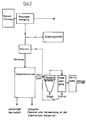
Figur 7- die Blockdarstellung der Stoffrückführung aus der Abgasreinigung.
- Figure 1
- 1 shows a device for carrying out the method according to the invention in a schematic sectional illustration in a first embodiment,
- Figure 2 to 4
- each the device in a modified version,
- Figure 5
- 1 shows a gas cleaning device as part of the device according to FIGS. 1 to 4 in a first embodiment in a schematic block diagram,
- Figure 6
- the gas cleaning device in a second embodiment, also in a schematic block diagram and
- Figure 7
- the block diagram of the material return from the exhaust gas cleaning.
Wie die Figur 1 der Zeichnung zeigt, besteht das erste dargestellte Ausführungsbeispiel der Vorrichtung 1 im wesentlichen aus den folgenden Komponenten:
einer Anordnung von Vorratsbehältern 2, einem Gemengemischer 3, einem Glasschmelzofen 4, einer Glasverarbeitungsmaschine 5, einem Abgaskühler 6 und einer Gasreinigungseinrichtung 7.As FIG. 1 of the drawing shows, the first illustrated embodiment of the device 1 essentially consists of the following components:
an arrangement of
Die Vorratsbehälter 2 dienen zur Aufnahme und Speicherung von einerseits Müllverbrennungsasche 80 und andererseits Zuschlagstoffen 81. An ihrem unteren Ende weisen die Vorratsbehälter 2 jeweils eine Dosierschleuse 20, z. B. eine Zellenradschleuse, auf. Diese Dosierschleusen 20 münden in eine gemeinsame Fördereinrichtung 21, hier ein Schnekkenförderer, der in den oberen Teil des Gemengemischers 3 mündet. Der Gemengemischer 3 besitzt ein im wesentlichen trichterförmiges, nach unten enger werdendes Gehäuse 30 sowie eine in diesem Gehäuse 30 angeordnete Mischerschnecke 31. Die Mischerschnecke 31 verläuft parallel zur Innenseite der seitlichen Wandung des Gehäuses 30 und ist sowohl um ihre eigene Achse als auch um eine zentral in vertikaler Richtung durch das Gehäuse 30 des Gemengemischers 3 verlaufende Achse drehbar. Im oberen Teil des Gehäuses 30 ist ein Feststoffeinlaß 32 vorgesehen, der mit der zuvor erwähnten Fördereinrichtung 21 verbunden ist. Am unteren Ende des Gehäuses 30 des Gemengemischers 3 ist ein Feststoffauslaß 33 vorgesehen, der in eine Gemengeaufgabevorrichtung 46 mündet. Die Gemengeaufgabevorrichtung 46 bildet bereits einen Teil des Glasschmelzofens 4. Der Glasschmelzofen 4 besteht aus einer Wanne 41 aus Feuerfestmaterial, die nach oben durch einen Oberbau 42, ebenfalls aus Feuerfestmaterial, abgedeckt ist. Die Wanne 41 und der Oberbau 42 ruhen auf einer Tragkonstruktion 40, die hier aus Stahlträgern gebildet ist. Außenseitig ist der Oberbau 42 des Glasschmelzofens 4 von einem gasdichten Mantel 42′ umgeben, der aus Stahlblech besteht und der bis zum oberen Rand der Wanne 41 reicht und dort mit dieser dichtend verbunden ist. Von oben her sind, durch den Oberbau 42 und den Mantel 42′ verlaufend, Heizelektroden 43 gasdicht in das Innere des Glasschmelzofens 4 geführt. Das Innere des Glasschmelzofens 4 ist in zwei unterschiedliche Bereiche aufgeteilt, nämlich einen Schmelzteil, der in der Figur 1 links liegt, und einen Erhitzungsteil, der in der Figur 1 rechts liegt. Die Aufteilung des Glasschmelzofens 4 in die beiden genannten Bereiche erfolgt durch einen als Teil des Oberbaus 42 ausgebildeten, von diesem nach unten vorragenden, abgehängten scheitrechten Bogen 44, der im Betrieb des Glasschmelzofens 4 bis knapp über die Oberfläche 84′ einer in dem Ofen 4 befindlichen Glasschmelze 84 reicht und eine vertikale Trennwand für den Gasraum des Ofens 4 bildet. Weiterhin ist unterhalb des Bogens 44 ein parallel zu diesem quer durch den Glasschmelzofen 4 verlaufendes Kühlmittelrohr 45 vorgesehen, welches genau in Höhe der Oberfläche 84′ der Glasschmelze 84 liegt und dazu dient, die Glasschmelze 84 in der Umgebung des Rohres 45 zum Erstarren zu bringen. Am rechten Ende des Glasschmelzofens 4 ist ein Glasschmelzeauslauf 48 vorgesehen, dem eine hier nur schematisch dargestellte Glasverarbeitungsmaschine 5 nachgeschaltet ist. Ebenfalls am rechten Ende des Glasschmelzofens 4 ist schließlich noch eine durch den Oberbau 42 nach oben verlaufende Abgas-Abzugsöffnung 47 vorhanden.The
Mit der Abgas-Abzugsöffnung 47 der Glasschmelzofens 4 ist eine wärmeisolierte Gasleitung 60 verbunden, die zum Gaseingang 61 des Abgaskühlers 6 führt. Außer dem Gaseingang 61 weist der Abgaskühler 6 einen Gasausgang 62 sowie einen Auslaß 63 für Kondensationsprodukte auf, wobei Gasausgang 62 und Auslaß 63 am unteren Ende des Abgaskühlers 6 angeordnet sind. Weiterhin weist der Abgaskühler 6 Mittel 65 zur Führung sowie zur Zuführung und Abführung eines Kühlmittels, z. B. Kühlwasser oder Kühlluft, auf. Oberhalb des Abgaskühlers 6 ist eine mechanische Reinigungsvorrichtung 66 angedeutet, mittels welcher die abgasführenden Teile des Abgaskühlers 6 kontinuierlich oder periodisch von den dort infolge der Abgas-Abkühlung anfallenden Kondensationsprodukten gereinigt werden können. Der zugehörige Auslaß 63 des Abgaskühlers 6 für die Kondensationsprodukte ist über eine weitere Fördereinrichtung 64, hier ebenfalls ein Schneckenförderer, mit der Aufgabeseite des Gemengemischers 3, d. h. dem oberen Teil von dessen Innerem, verbunden. Der obere Teil des Gehäuses 30 des Gemengemischers 3 weist hierzu eine einen Einlaß 36 für die Kondensationsprodukte darstellende Öffnung auf. Über eine Weiche 69 am oberen Ende der Fördereinrichtung 64 können bedarfsweise die Kondensationsprodukte zum Teil oder gänzlich ausgeschleust werden.A heat-insulated
Dem Gasausgang 62 des Abgaskühlers 6 ist ein erstes Sauggebläse 67 nachgeordnet, welches ausgangsseitig mit einer Verbindungsleitung 68 verbunden ist. Diese Verbindungsleitung 68 führt zu einem Gaseinlaß 34 des Gemengemischers 3, wobei der Gaseinlaß 34 im unteren Teil des Gehäuses 30 angeordnet und so ausgebildet ist, daß zwar ein Eintritt von Gas in das Innere des Gehäuses 30 möglich ist, jedoch ein Austritt von Gemenge aus dem Inneren des Gehäuses 30 in die Leitung 68 ausgeschlossen ist.Downstream of the
An dem dem Gaseinlaß 34 entgegengesetzten Ende, d. h. am oberen Ende des Gemengemischers 3, ist ein Gasauslaß 35 vorgesehen, dem ein zweites Sauggebläse 70 nachgeschaltet ist. Dabei sind das erste Sauggebläse 67 und das zweite Sauggebläse 70 in ihrer Leistung regelbar, wozu sie vorzugsweise mit einer gemeinsamen Steuereinrichtung verbunden sind.At the end opposite the
Von dem Ausgang des zweiten Sauggebläses 70 führt eine Gasleitung 71 zu der Gasreinigungseinrichtung 7, die mit an sich bekannten Komponenten ausgebildet sein kann und die deshalb hier nicht näher ausgeführt ist. Ausgangsseitig ist der Gasreinigungseinrichtung 7 schließlich ein Kamin 79 nachgeschaltet.From the outlet of the
Das in Figur 2 dargestellte Ausführungsbeispiel der Vorrichtung entspricht in seinen wesentlichen Teilen dem zuvor anhand von Figur 1 beschriebenen Ausführungsbeispiel. Im Unterschied zu der Figur 1 ist hier jedoch der Glasschmelzofen 4 etwas anders ausgeführt. Der bei dem zuerst beschriebenen Ausführungsbeispiel im Glasschmelzofen 4 vorhandene Bogen 44 ist bei dem Glasschmelzofen 4 gemäß Figur 2 entfallen, d. h. der Oberbau 42 des Glasschmelzofens 4 ist als durchgehendes Bauteil mit einem einteiligen Ofeninneren ausgebildet. Weiterhin ist das Kühlmittelrohr 45 bei dem Glasschmelzofen gemäß Figur 2 in Richtung zum Auslaufende des Glasschmelzofens 4, d. h. in der Figur 2 nach rechts verschoben. Hierdurch kann sich das auf der Glasschmelze 84 im Inneren des Glasschmelzofens 4 schwimmende Gemenge 83 über annähernd die gesamte Oberfläche der Glasschmelze 84 im Glasschmelzofen 4 ausbreiten. Hierdurch wird erreicht, daß bereits ein großer Teil der aus der Glasschmelze 84 aufsteigenden Gase und Dämpfe in der aufliegenden Gemengedecke kondensiert. Die Abgasmenge wird so vermindert. Gleichzeitig wird die Temperatur des den Glasschmelzofen 4 durch die Öffnung 47 verlassenden Gases vermindert. Sie beträgt hier etwa 300 bis 500°C.The embodiment of the device shown in FIG. 2 corresponds in its essential parts to the embodiment previously described with reference to FIG. 1. In contrast to FIG. 1, however, the
Um auch bei dieser Vorrichtung eine sichere Zerstörung von Dioxinen und/oder Furanen im austretenden Abgas zu gewährleisten, ist in die der Gasabzugsöffnung 47 nachgeschaltete Gasleitung 60 ein separater Gaserhitzer 91 eingesetzt. Dieser Gaserhitzer 91 ist in der Figur 2 lediglich schematisch angedeutet und kann von an sich bekannter Bauart sein. In ihm wird das ankommende Abgas für eine Zeit von wenigstens 1,5 s auf eine Temperatur von wenigstens 1200°C erhitzt.In order to ensure that dioxins and / or furans in the exiting exhaust gas are also reliably destroyed in this device, a
Der weitere Aufbau der Vorrichtung gemäß Figure 2 entspricht dem Aufbau der Vorrichtung gemäß Figur 1, wobei gleiche Teile der Vorrichtungen mit gleichen Bezugsziffern bezeichnet sind.The further structure of the device according to FIG. 2 corresponds to the structure of the device according to FIG. 1, the same parts of the devices being designated with the same reference numbers.
Das dritte Ausführungsbeispiel der Vorrichtung gemäß Figur 3 ist insbesondere dadurch gekennzeichnet, daß der Abgaskühler 6 mit der zugehörigen Gasleitung 60 hier nicht vorhanden ist. Der Glasschmelzofen 4 entspricht hier im wesentlichen dem Glasschmelzofen, wie er in Figur 2 dargestellt ist mit dem Unterschied, daß hier eine Gasabzugsöffnung 47′ am Aufgabeende, d. h. am linken Ende des Glasschmelzofens 4 vorgesehen ist. Diese Gasabzugsöffnung 47′ steht über eine kurze Gasleitung 60′ mit der Ansaugseite des ersten Sauggebläse 67 in Verbindung. Von dort führt die bereits beschriebene Verbindungsleitung 68 zum Gemengemischer 3.The third exemplary embodiment of the device according to FIG. 3 is particularly characterized in that the
Dieser Gemengemischer 3 ist, da keine Kondensationsprodukte aus dem Abgaskühler zugeführt werden müssen, in seinem oberen Teil ohne die bei den zuvor beschrieben Vorrichtungen vorhandene Aufgabeöffnung 36 ausgebildet.Since no condensation products have to be supplied from the exhaust gas cooler, this
Die für die sichere Zerstörung von Dioxinen und/oder Furanen erforderliche Erhitzung des Abgases erfolgt hier ebenfalls in einem separaten Gaserhitzer 91, der bei der Vorrichtung gemäß Figur 3 in die vom zweiten Sauggebläse 70 zur Gasreinigungseinrichtung 7 führende Abgasleitung 71 eingeschaltet ist.The heating of the exhaust gas required for the safe destruction of dioxins and / or furans also takes place here in a
Die letzte dargestellte Variante der Vorrichtung gemäß Figur 4 entspricht weitestgehend dem Ausführungsbeispiel gemäß Figur 3, wobei der Unterschied hier darin liegt, daß der separate Gaserhitzer 91 für die Erhitzung des Abgases und die Zerstörung von eventuell in diesem vorhandenen Dioxinen und/oder Furanen der Gasreinigungseinrichtung 7 nachgeordnet ist und in die zum Kamin 79 führende Gasleitung eingebaut ist. Diese Ausführung der Vorrichtung bietet insbesondere den Vorteil, daß die aufzuheizende Gasmenge hinter der Gasreinigungseinrichtung 7 nur noch etwa 50 % der ursprünglichen Gasmenge beträgt, d. h. es wird Heizenergie eingespart.The last illustrated variant of the device according to FIG. 4 largely corresponds to the exemplary embodiment according to FIG. 3, the difference here being that the
Im folgenden soll ein Ablaufbeispiel des mit der zuvor anhand von Figur 1 beschriebenen Vorrichtung durchführbaren Verfahrens beschrieben werden:
Aus einer Müllverbrennungsanlage oder von einer Deponie stammende Müllverbrennungsasche 80 wird dem ersten Vorratsbehälter 2 zugeführt. Die weiteren Vorratshbehälter 2 werden mit erforderlichen Zuschlagstoffen 81, insbesondere Sand und Phonolit sowie ggf. Glasscherben, befüllt. Mittels der Dosierschleusen 20 werden in vorbestimmten Mengenverhältnissen Müllverbrennungsasche 80 sowie die Zuschlagstoffe 81 aus den Vorratsbehältern 2 entnommen und mittels der Fördereinrichtung 21 in das Innere des Behälters 30 des Gemengemischers 3 gefördert. Dort werden die einzelnen Bestandteile mittels der Mischerschnecke 31 zu einem homogenen, aufzuschmelzenden Gemenge 82 gemischt. Fertiges, aufzuschmelzendes Gemenge 82 wird durch den Feststoffauslaß 33 des Gemengemischers 3 mittels der Gemengeaufgabevorrichtung 46 in das Innere des Glasschmelzofens 4 gefördert. Im laufenden Betrieb ist der Glasschmelzofen 4 bis zu einer bestimmten Höhe mit Glasschmelze 84 gefüllt. Dabei liegt die Oberfläche 84′ der Glasschmelze 84 genau in Höhe des Kühlmittelrohres 45 und knapp unterhalb des Bogens 44.A sequence example of the method which can be carried out with the device previously described with reference to FIG. 1 is to be described below:
The
Das von der Gemengeaufgabevorrichtung 46 zugeführte Gemenge schwimmt als schmelzendes Gemenge 83 auf der Glasschmelze 84 und verteilt sich auf dessen Oberfläche 84′ im Schmelzteil, d. h. in Figur 1 linken Teil, des Glasschmelzofensofens 4. Da die Glasschmelze 84 in der Umgebung des Kühlmittelrohres 45 mittels des durchströmenden Kühlmittels zum Erstarren gebracht wird, kann das schmelzende Gemenge 83 nicht in den Teil des Glasschmelzofens jenseits des Bogens 44 und des Kühlmittelrohres 45 gelangen. Die für das Aufschmelzen des aufzuschmelzenden Gemenges 83 erforderliche Wärmeenergie wird dabei mittels der Heizelektroden 43, die mit ihrem unteren Teil in die Glasschmelze 84 ragen, als Joulsche Energie in der Glasschmelze 84 erzeugt, wobei die Glasschmelze 84 den Ohmschen Widerstand bildet.The batch supplied by the
Während des Aufschmelzens des Gemenges 83 steigen Abgase 85 aus diesem auf, wobei das Abgas hier eine Temperatur zwischen etwa 100 und 1000°C aufweist und im wesentlichen SOuu2u, HCl, Chloride, Sulfate, Kohlendioxid, Alkali- und Schwermetalldämpfe sowie Dioxine und/oder Furane enthalten kann.During the melting of the
Dieses Abgas 85 tritt durch den Spalt zwischen der Unterseite des Bogens 44 und dem Kühlmittelrohr 45 in den rechten Teil des Inneren des Glasschmelzofens 4 ein. In diesem Teil des Glasschmelzofens 4 ist die Oberfläche 84′ der Glasschmelze 84 gemengefrei. Die in diesem Teil des Glasschmelzofens 4 befindliche Glasschmelze 84 hat eine Temperatur von etwa 1400°C. Die Temperatur im oberen Teil des Glasschmelzofens 4 oberhalb der Schmelze 84 beträgt hier demnach wenigstens etwa 1300 - 1350°C. Um hier eine möglichst hohe Temperatur zu erzielen, ist zweckmäßig der Oberbau 42 des Glasschmelzofens 4 stark wärmeisoliert. Das in diesen Bereich des Glasschmelzofens 4 eintretende Abgas wird nun durch Wärmeaufnahme aus der Schmelze nacherhitzt, wobei durch Einstellung der Strömungsgeschwindigkeit und durch Wahl entsprechender Dimensionen des Glasschmelzofens 4 dafür gesorgt wird, daß die Temperatur des heißen Abgases 86 zumindest für eine Zeit von 1,5 s eine Höhe von mindestens 1200°C erreicht. Hierdurch werden die eventuell in dem ankommenden Abgas 85 enthaltenen Dioxine und/oder Furane sicher zerstört, so daß das heiße Abgas 86 nur noch die Chloride, Sulfate, das Kohlendioxid sowie die Alkali- und Schwermetalldämpfe enthält.This
Dieses heiße Abgas 86 wird durch die wärmeisolierte Leitung 60 abgezogen, wobei deren Wärmeisolierung im wesentlichen dazu dient, eine Abkühlung und damit Kondensation des heißen Abgases 86 innerhalb der Leitung 60 zu verhindern. Das heiße Abgas 86 gelangt durch den Gaseingang 61 in den Abgaskühler 6, wo es auf eine Temperatur zwischen 300 und 500°C abgekühlt wird. Dabei kondensiert ein Teil des Abgases und schlägt sich innerhalb des Abgaskühlers 6 nieder. Die anfallenden Kondensationsprodukte 88 werden mittels der Reinigungsvorrichtung 66 periodisch oder kontinuierliche entfernt und dem unterhalb des Abgaskühlers 6 gelegenen Auslaß 63 für die Kondensationsprodukt zugeführt. Von dort werden die Kondensationsprodukte 88 mittels der Fördereinrichtung 64 durch den Einlaß 36 für die Kondensationsprodukte in das Innere des Gemengemischers 3 geführt und somit in das aufzuschmelzende Gemenge 82 rückgeführt. Bei Bedarf können die Kondensationsprodukte 88 über die Weiche 69 ganz oder teilweise ausgeschleust werden.This
Das durch den Gasausgang 62 aus dem Abgaskühler austretende vorgekühlte Abgas 87 gelangt zu dem ersten Sauggebläse 67. Dieses sorgt dafür, daß auf seiner Ansaugseite, d. h. innerhalb des Abgaskühlers 6, in der Leitung 60 sowie im Inneren des Glasschmelzofens 4, ein Unterdruck gegenüber dem Umgebungsluftdruck herrscht. Förderseitig sorgt das Sauggebläse 67 dafür, daß das aus diesem austretende, vorgekühlte Abgas 87 innerhalb der Verbindungsleitung 68 zum Gemengemischer 3 einen Überdruck gegenüber dem Umgebungsluftdruck erhält. Dieses unter einem Überdruck stehende vorgekühlte Abgas 87 wird durch den Gaseinlaß 34 in das aufzuschmelzende Gemenge 82 im Inneren des Gemengemischers 3 geleitet. Während des Durchströmens des Abgases 87 kühlt sich dieses unter weiterer Kondensation auf eine Temperatur von etwa 20 - 50°C ab und tritt an der Oberfläche des aufzuschmelzenden Gemenges 82 als kaltes Abgas aus. Die Mischerschnecke 31 sorgt dabei außer für eine Durchmischung der einzelnen Bestandteile des aufzuschmelzenden Gemenges 82 dafür, daß letzteres locker und gasdurchlässig bleibt. Aufgrund der starken Abkühlung kondensieren innerhalb des aufzuschmelzenden Gemenges 82 auch niedrig kondensierende Dämpfe, wie z. B. Schwermetalldämpfe. Das durch den Gasauslaß 35 des Gemengemischers 3 austretende kalte Abgas 89 enthält dann im wesentlichen nur noch HCl und SO₂.The
Das dem Gasauslaß 35 nachgeschaltete zweite Sauggebläse 70 sorgt dabei im Zusammenwirken mit einer entsprechenden Steuereinheit sowie Drucksensoren dafür, daß der Druck des kalten Abgases 89 im oberen Teil des Gemengemischers 30 im wesentlichen gleich dem Umgebungsluftdruck bleibt.The
Dies sorgt dafür, daß weder Abgase in die Umgebung noch Falschluft in das System gelangen kann.This ensures that no exhaust gases can get into the environment and no false air can enter the system.
Das kalte Abgas 89, im wesentlichen ein konzentriertes Gas aus Chloriden und SO₂ sowie SO₃, wird über die Leitung 71 der Gasreinigungseinrichtung 7 zugeführt und dort weiter gereinigt. Die aus der Gasreinigungseinrichtung noch austretenden verbleibenden Rest-Abgase 90, insbesondere N₂, CO₂ und geringe Mengen Sauerstoff werden schließlich durch den Kamin 79 in die Umgebung entlassen. Dabei ist eine Gefährdung oder Schädigung der Umwelt aufgrund der das Rest-Abgas 90 bildenden, relativ harmlosen Bestandteile ausgeschlossen.The
Außer dem Rest-Abgas 90 liefert die Vorrichtung 1 gemäß dem dargestellten Ausführungsbeispiel nach dem beschriebenen Verfahren als wiederverwendbaren Rohstoff Glaskörper 9, die mittels der Glasverarbeitungsmaschine 5 aus der auslaufenden Glasschmelze 84˝ in kontinuierlicher Fertigung hergestellt werden. Diese Glaskörper 9 können beispielsweise als Schotter oder Betonzuschlag verwendet werden.In addition to the
Die Größe des Glasschmelzofens 4 und damit das Volumen der in ihm befindlichen Glasschmelze 84 werden zweckmäßig so groß gewählt, daß auftretende Schwankungen in der Zusammensetzung der Müllverbrennungsasche das erschmolzene Glas nicht kurzfristig in seinem Chemismus vollständig verändern können. Auftretende Änderungen in der Zusammensetzung der Glasschmelze 84 können sehr schnell z. B. anhand der Änderungen des elektrischen Widerstandes der Glasschmelze 84 zwischen den Elektroden 43 erkannt werden. Diese Meßwerte können dann zur Regelung der Mischung der Müllverbrennungsasche 80 und der einzelnen Zuschlagstoffe 81, insbesondere eines Zuschlagstoffes mit einem gewissen Alkaligehlat, z. B. Phonolit, verwendet werden.The size of the
Eine weitere Möglichkeit der Korrektur der Zusammensetzung der Glasschmelze 84 besteht darin, daß die Kristallisationserscheinungen am fertigen Glasprodukt beobachtet werden. Spezifische Glaszusammensetzungen im Grenzbereich bilden bestimmte Kristalle, welche leicht im fertigen Glas erkannt werden können und die angeben, ob und nach welcher Seite sich die Zusammensetzung des Glases verändert hat. Dementsprechend können die Mengen der zu mischenden Müllverbrennungsasche 80 und Zuschlagstoffe 81 variiert werden.Another way of correcting the composition of the
Anhand der Figuren 5 und 6 sollen im folgenden zwei Ausführungsbeispiele für die Gasreinigungseinrichtung 7 erläutert werden, wobei die Figur 5 eine Naß-Gasreinigungseinrichtung 7 und die Figur 6 eine Trocken- bzw. Halbtrocken-Gasreinigungseinrichtung 7 zeigt.Two exemplary embodiments of the
Gemäß Figur 5 gelangt das kalte Abgas 89 durch die Leitung 71 zu einer ersten Wäscherstufe 72. In dieser ersten Wäscherstufe wird insbesondere HCl aus dem Abgas ausgewaschen. In einer zweiten Wäscherstufe 72′ wird nachfolgend insbesondere SO₂ ausgewaschen. In einem nachfolgenden Tropfenabscheider 73 werden mitgerissene Wassertropfen abgeschieden. In einer Gas-Aufheizstrecke 74 wird das Gas auf eine geeignete Temperatur zwischen 30 und 90°C erwärmt und anschließend einer Aktivkohle-Filterstufe 78 zugeführt. Nach deren Durchlaufen gelangt das Rest-Abgas 90, im wesentlichen zusammengesetzt aus N₂, CO₂ und geringen Mengen Sauerstoff durch den Kamin 79 in die Umgebung.According to FIG. 5, the
In der ersten Wäscherstufe 72 für die HCl-Abscheidung ist ein pH-Wert im sauren Bereich, vorzugsweise < 1 einzustellen. Die zweite Wäscherstufe 72′ für die SO₂-Abscheidung wird dagegen vorzugsweise basisch mit pH-Werten von z. B. 6 - 7,5 betrieben. Die beiden Wäscherstufen 72 und 72′ werden vorzugsweise im Gegenstrom betrieben, können aber auch im Gleichstrom betrieben werden. Eventuell noch vorhandene Quecksilbermengen im Abgas 89 werden vollständig in der Aktivkohle-Fiterstufe 78 abgeschieden. Die aus den Wäscherstufen 72 und 72′ sowie dem Tropfenabscheider 73 abgegebenen Ausstoßmengen an Abwasser und Schlamm werden zweckmäßig einer Abwasser-Reinigungsanlage zugeführt.In the
Das zweite Ausführungsbeispiel der Gasreinigungseinrichtung 7 gemäß Figur 2b besitzt als erste Komponente einen Sättiger 75, dem das kalte Abgas 89 ebenfalls über die Leitung 71 zugeführt wird. Nach Sättigung des Abgases im Sättiger 75 wird es einem Wirbelschicht- oder Sprühadsorber 76 zugeführt. Der Sprühadsorber wird vorzugsweise mit NaOH oder Ca(OH)₂ in wässriger Lösung beaufschlagt. Das austretende Gas wird in einer Gas-Temperierstufe 77 auf die für die auch hier folgende Aktivkohle-Filterstufe 78 optimale Temperatur gebracht. Das letztendlich austretende Restabgas 90 gelangt auch hier wieder durch den Kamin 79 in die Umgebung.The second exemplary embodiment of the
Das hier anfallende Abwasser sowie die hier anfallenden Feststoffe werden ebenfalls einer weiteren Reinigungseinrichtung, z. B. Abwasser-Reinigungsanlage, bzw. Deponierung oder Wiederverwendung zugeführt.The resulting wastewater and the resulting solids are also a further cleaning device, for. B. sewage treatment plant, or landfill or reuse.
Aufgrund der relativ einfachen, definierten Zusammensetzung des Abgases 89 können die Gasreinigungseinrichtungen 7 zur Rückgewinnung von Natriumchlorid und Natriumsulfat in relativ reiner Form dienen. Diese Rohstoffe wiederum können für die Herstellung z. B. von Soda verwendet werden.Due to the relatively simple, defined composition of the
Wie bereits beschrieben, wird das in relativ geringen Mengen anfallende Abgas entweder direkt oder nach dem Durchleiten durch das Gemenge der Staubabscheidung in einem Staubabscheider zugeführt und danach in einer Naßreinigung gereinigt. In einer weiteren Stufe wird das Abgas dann durch einen Aktivkohlefilter durchgeführt, wobei das daraufhin entstehende Reingas ohne weiteres in die Atmosphäre abgelassen werden kann, da es keine umweltbelastenden Partikel oder Gasanteile mehr enthält.As already described, the exhaust gas obtained in relatively small amounts is fed to the dust separation either directly or after passing through the batch in a dust separator and then cleaned in a wet cleaning process. In a further stage that will be Exhaust gas is then passed through an activated carbon filter, and the resulting clean gas can then be easily discharged into the atmosphere, since it no longer contains particles or gas components that are harmful to the environment.
Es ist für den Fachmann überraschend, daß eine wesentliche Verringerung der Umweltbelastung erfindungsgemäß dadurch erreicht werden kann, daß sowohl der abgeschiedene Staub als auch das Filtrat aus der Naßeinrichtung beziehungsweise die Schlämme aus der Gasreinigung dem Gemenge aus Zuschlagstoffen und Müllverbrennungs-Filterasche wieder zugefügt werden und nach einer Mischung mit dem Gemenge wieder in den Glasschmelzofen eingeführt werden.It is surprising to the person skilled in the art that a significant reduction in the environmental impact can be achieved according to the invention by adding both the separated dust and the filtrate from the wet device or the sludge from gas cleaning to the mixture of additives and waste incineration filter ash and after a mixture with the batch are reintroduced into the glass melting furnace.
Das erfindungsgemäße Verfahren hat mehrere Vorteile. Erstens werden nur noch zwei Materialien aus dem Prozeß ausgetragen. Einmal der Werkstoff des Glases, welcher im Wegebau oder in ähnlichen Anwendungsfällen Verwendung finden kann und zweitens die Glasgalle, die sich zusammensetzt aus all den Salzen, deren Löslichkeitsgrenze in der Glasschmelze bei dem Glasschmelzprozeß und dem Grad des jeweils eingeschmolzenen Glases überschritten wird.The method according to the invention has several advantages. First, only two materials are removed from the process. Firstly, the material of the glass, which can be used in road construction or in similar applications, and secondly, the glass bile, which is composed of all the salts, the solubility limit of which is exceeded in the glass melt during the glass melting process and the degree of the melted glass.
Die gesamte aus dem Prozeß ausgetragene Schadstoffmenge verringert sich dabei um die in der Gasreinigung anfallenden Stoffe und die darin enthaltenen Schwermetalle. Da die Löslichkeitsgrenze für die Metalle und im weiteren Sinne für alle Schwermetalle in der Glasschmelze bei dem Prozeß nicht erreicht wird, werden durch die Rückführung sämtliche Schwermetalle auslaugfest in das Glas eingebunden.The total amount of pollutants discharged from the process is reduced by the substances in gas cleaning and the heavy metals contained therein. Since the solubility limit for the metals and, in a broader sense, for all heavy metals in the glass melt is not reached during the process, all heavy metals are incorporated in the glass in a leach-proof manner by recycling.
Für den Fachmann überraschend ist weiterhin, daß der Rückstand Glasgalle relativ sauber ist, da infolge der gegenüber dem vorgeschlagenen Verfahren größeren Gallemenge eine exaktere Abscheidung möglich ist und die Galle damit einen größeren Reinheitsgrad erreicht. Es ergibt sich damit die Möglichkeit, diese Glasgalle als Rohstoff in der chemischen Industrie abzusetzen. Der Anteil der Glasgalle beträgt etwa 5 - 10 % der eingegebenen Müllverbrennungsaschenmenge.It is also surprising for the person skilled in the art that the residue of glass bile is relatively clean, since, owing to the larger amount of bile compared to the proposed method, a more precise separation is possible and the bile to achieve a greater degree of purity. This gives the opportunity to sell this glass bile as a raw material in the chemical industry. The proportion of glass bile is about 5 - 10% of the amount of waste incineration ash entered.
Claims (32)
- Process for transforming solid, substantially anhydrous waste materials into glass, wherein garbage incineration ash (80) is used as waste material, the waste materials are mixed with one or more flux powders (81) to form a glass batch (82) to be melted, the glass batch by the largest part thereof is melted into a melting (84) by heating and by a small part thereof is extracted from the smelting glass batch (83) as exhaust gas (85), solid glass bodies (9) are produced from the melting by casting and cooling, the hot exhaust gas extracted under sealed conditions against the ambiant air is recycled into the glass batch and at this location cooled to 20 to 50 °C, the condensation products produced by the cooling are smelted with the glass batch, and the cold exhaust gas (89) flowing out of the glass batch to be melted is purified in a gas cleaning process for contaminated gas as is known as such.
- Process as claimed in claim 1, characterized in that the hot exhaust gas (85) flowing out of the smelting glass batch (83) is reheated up to a temperature of at least 1200 °C for at least 1,5 s, thereafter is pre-cooled to a temperature of between 200 to 300 °C while condensating partly, subsequently is recycled into the glass batch (82) to be melted and at this location is cooled to 20 to 50 °C while condensating further, and that the condensation products produced during the pre-cooling are recycled into the glass batch to be melted and/or are exhausted.
- Process as claimed in claim 2, characterized in that the reheating of the hot exhaust gas (85) is accomplished in a separate reheater (91).
- Process as claimed in claim 2, characterized in that the melting (84) at a part of the surface (84') thereof is kept free of glass batch and that the hot exhaust gas (85) after flowing out of the smelting glass batch (83) is conducted across a surface of the melting free of glass batch and is reheated by picking up heat from the melting.
- Process as claimed in claim 1, characterized in that the cold exhaust gas (89) flowing out of the glass batch (82) to be melted is reheated up to a temperature of at least 1200 °C for a time of at least 1,5 s and thereafter is conducted to a cleaning process for contaminated gas.
- Process as claimed in claim 1, characterized in that the exhaust gas flowing out of the cleaning process for contaminated gas is reheated up to a temperature of at least 1200 °C for a time of at least 1,5 s.
- Process as claimed in the claims 1 to 6, characterized in that a liquid layer of gall of alkali salts or alkaline earth salts is produced at that part of the surface of the melting (84) covered with glass batch (83) and that the layer is maintained at a layer thickness of between 2 and 5 cm by extraction if required.
- Process as claimed in claim 7, characterized in that a layer of gall of substantially sodium sulfate or -chloride or calcium sulfate or -chloride or lithium sulfate or -chloride or a mixture thereof is used, and that this layer of gall is produced during the melting process by reaction of calcium sulfate, calcium chloride, magnesium sulfate and/or magnesium chloride added to the glass batch (82) together with the garbage incineration ash (80) and/or as a separate flux powder during the melting process.
- Process as claimed in claim 7, characterized in that a layer of gall of calcium sulfate and/or magnesium sulfate is used at high melting temperatures and/or lack of alkali, and that this layer of gall is directly produced of the calcium sulfate and/or magnesium sulfate added together with the glass batch (82) or as a separate flux powder.
- Process as claimed in claims 1 to 9, characterized in that SiO₂ containing substances, particularly sand and/or phonolite are used as flux powder.
- Process as claimed in claim 10, characterized in that the hot exhaust gas (85) and the gas flowing out of the smelting glass batch (83) are extracted under vacuum and pre-cooled, that the pre-cooled exhaust gas is put under pressure, and that the exhaust gas is conducted through the glass batch (82) to be melted in a reverse current and is controlled such, that the pressure of the cold exhaust gas (89) flowing out of the glass batch to be melted is substantially equal to the pressure of the ambiant air.
- Process as claimed in claims 1 to 11, characterized in that the dust and/or sludge produced in the gas cleaning is recycled to the glass batch (82).
- Process as claimed in claim 12, characterized in that the exhaust gas (89) is conducted through an activated carbon filter after the gas cleaning.
- Process as claimed in claim 12 or 13, characterized in that the exhaust gas (89) is cooled before or after the gas cleaning.
- Apparatus for executing the process as claimed in claim 1, comprising a closed glass batch mixer (3) with a solid particle inlet (32) for the input of garbage incineration ash (80) to be mixed and flux powder (81), a solid particle outlet (33) for the output of the prepared glass batch (82) to be melted, a gas inlet (34) and a gas outlet (35), a closed glass melting furnace (4) with a glass batch input device (46) at the one end of the furnace connected with the solid particle outlet (33) of the glass batch mixer (3), with at least one exhaust gas outlet opening (47) and a melting outlet (48) provided at the other end of the furnace, and gas purifiers (7) with the inlet thereof connected with the gas outlet (35) of the glass batch mixer (3).
- Apparatus as claimed in claim 15, characterized by an exhaust gas cooler (6) comprising a gas inlet (61) connected with the exhaust gas outlet opening (47) of the glass melting furnace (4), a gas outlet (62) connected with the gas inlet (34) of the glass batch mixer (3), and an outlet for the condensation products connected with the solid particle input side of the glass batch mixer (3).
- Apparatus as claimed in claim 15 or 16, characterized in that the glass melting furnace (4) is completely electrically heatable by means of heating electrodes and/or -rods (43) protruding from the top into the interior of the furnace.
- Apparatus as claimed in the claims 15 to 17, characterized in that the top construction (42) of the glass melting furnace (4) is lined at the outside thereof with a gas-tight case (42').
- Apparatus as claimed in the claims 15 to 18, characterized in that a cooling medium pipe (45) is conducted across the glass melting furnace (4) at the level of the surface (84') of the melting (84).
- Apparatus as claimed in the claims 15 to 19, characterized in that the interior of the top construction (42) of the glass melting furnace (4) is divided into two sections by a horizontal and straight bow (44) arranged transversely and extending close to the surface (84') of the melting (84) and forming a vertical partition wall, and that the cooling medium pipe (45) runs in parallel with the bow (44).
- Apparatus as claimed in claim 20, characterized in that the exhaust gas outlet opening (47) of the glass melting furnace (4) is positioned at the furnace end adjacent to the melting outlet (48) thereof.
- Apparatus as claimed in the claims 16 to 21, characterized in that the exhaust gas outlet opening (47) of the glass melting furnace (4) is directly connected with the gas inlet (61) of the exhaust gas cooler (6) by means of a heat-insulated gas pipe (60).
- Apparatus as claimed in the claims 16 to 21, characterized in that the exhaust gas outlet opening (47) of the glass melting furnace (4) is connected with the gas inlet (61) of the exhaust gas cooler (6) by arranging inbetween a dedicated gas heater (91).
- Apparatus as claimed in the claims 16 to 23, characterized in that the exhaust gas cooler (6) is provided with gas purifiers (66) for continuously or periodically removing the condensation products (88) produced there.
- Apparatus as claimed in the claims 16 to 24, characterized in that a conveyor means (64) is arranged between the outlet (63) for condensation products of the exhaust gas cooler (6) and the glass batch mixer (3) for continuously or periodically supplying the condensation products (88) of the exhaust gas cooler (6) to the glass batch mixer.
- Apparatus as claimed in the claims 16 to 25, characterized in that a first controllable extract fan (67) is positioned in a gas pipe (68) connecting the gas outlet (62) of the exhaust gas cooler (6) with the gas inlet (34) of the glass batch mixer (3).
- Apparatus as claimed in the claim 15 to 26, characterized in that the gas inlet (34) of the glass batch mixer (3) is positioned laterally at the glass batch mixer (3) and the gas outlet (35) of the glass batch mixer (3) is positioned at the input side thereof for solid particles.
- Apparatus as claimed in the claims 15 to 27, characterized in that in front of the solid particle inlet (32) of the glass batch mixer (3) several storage containers (2) for the garbage incineration ash (80) and the flux powder (81) are arranged with the containers each provided with dosing sluices (20) and conveyor means (21).
- Apparatus as claimed in the claims 15 to 28, characterized in that a second extract fan (70) is arranged in a gas pipe (71) connecting the gas outlet (35) of the glass batch mixer (3) with the gas purifiers (7), and that the second extract fan in connection with the first extract fan (67) by means of a common control unit in response to data of a pressure sensor in the gas outlet (35) of the glass batch mixer (3) is controllable such, that the pressure in the gas outlet (35) of the glass batch mixer (3) is substantially equal to the ambiant air pressure.
- Apparatus as claimed in the claims 15 to 29, characterized in that a glass processing machine (5) is arranged behind the melting outlet (48) of the glass melting furnace (4) with the glass processing machine continuously producing solid glass bodies (9) usable for addition to crushed stone or concrete out of the melting (84'') pouring out.
- Apparatus as claimed in the claims 15 to 30, characterized in that the gas purifiers (7) are wet gas purifiers and comprise one or more cleaning steps (72, 72'), a mist collector (73), a gas heating step (74) and an activated carbon filter step (78).
- Apparatus as claimed in the claims 15 to 30, characterized in that the gas purifiers (7) are dry gas purifiers or semi-dry gas purifiers and comprise a saturator (75), a fluid bed adsorber or spray adsorber (76), a gas temperature moderator (77) and an activated carbon filter step (78).
Priority Applications (1)
| Application Number | Priority Date | Filing Date | Title |
|---|---|---|---|
| AT89115675T ATE98204T1 (en) | 1988-09-10 | 1989-08-25 | PROCESS FOR TRANSFORMING SOLID, LARGELY WASTE FREE IN GLASS FORM AND DEVICE FOR CARRYING OUT THE PROCESS. |
Applications Claiming Priority (6)
| Application Number | Priority Date | Filing Date | Title |
|---|---|---|---|
| DE3830899 | 1988-09-10 | ||
| DE3830899 | 1988-09-10 | ||
| DE3841889A DE3841889A1 (en) | 1988-09-10 | 1988-12-13 | Process for converting solid, substantially anhydrous waste materials into the glass form (vitrification) and apparatus for carrying out the process |
| DE3841889 | 1988-12-13 | ||
| DE3904613 | 1989-02-16 | ||
| DE19893904613 DE3904613A1 (en) | 1989-02-16 | 1989-02-16 | Environmentally friendly process for converting solid waste materials into glass form (vitrification) |
Publications (3)
| Publication Number | Publication Date |
|---|---|
| EP0359003A2 EP0359003A2 (en) | 1990-03-21 |
| EP0359003A3 EP0359003A3 (en) | 1991-01-16 |
| EP0359003B1 true EP0359003B1 (en) | 1993-12-08 |
Family
ID=27198209
Family Applications (1)
| Application Number | Title | Priority Date | Filing Date |
|---|---|---|---|
| EP89115675A Expired - Lifetime EP0359003B1 (en) | 1988-09-10 | 1989-08-25 | Process for transforming solid, substantially anhydrous waste materials into glass, and apparatus therefor |
Country Status (6)
| Country | Link |
|---|---|
| EP (1) | EP0359003B1 (en) |
| JP (1) | JPH07102977B2 (en) |
| AU (1) | AU624414B2 (en) |
| DE (1) | DE58906363D1 (en) |
| DK (1) | DK169057B1 (en) |
| ES (1) | ES2047074T3 (en) |
Families Citing this family (24)
| Publication number | Priority date | Publication date | Assignee | Title |
|---|---|---|---|---|
| US4977837A (en) * | 1990-02-27 | 1990-12-18 | National Recovery Technologies, Inc. | Process and apparatus for reducing heavy metal toxicity in fly ash from solid waste incineration |
| CH680198A5 (en) * | 1990-07-06 | 1992-07-15 | Sulzer Ag | |
| DE4035777A1 (en) * | 1990-11-08 | 1992-05-14 | Noell Gmbh | METHOD FOR THE DISPOSAL OF DUST CONTAINING TOXIC HEAVY METALS, TOXIC ORGANIC MATERIALS AND SIMILAR COMPOUNDS |
| DE4111385A1 (en) * | 1991-04-09 | 1992-10-15 | Leybold Ag | Filter dust smelting with reduced electrode erosion - in which electrodes are inserted into glass from above into mixt. of dust and additives |
| DE4112162C1 (en) * | 1991-04-13 | 1992-07-30 | Beteiligungen Sorg Gmbh & Co Kg, 8770 Lohr, De | |
| WO1993001141A1 (en) * | 1991-07-11 | 1993-01-21 | Schoenhausen Horst | Process and device for the safe disposal of toxic residues |
| CZ278936B6 (en) * | 1991-09-23 | 1994-09-14 | Crystalex Sp | Vitrification process of powder waste, particularly fly ash from refuse incinerating plants |
| FR2684573B1 (en) * | 1991-12-05 | 1994-10-07 | Mediterranee Const Ind | PROCESS FOR THE TREATMENT OF SOLID RESIDUES FROM THE PURIFICATION OF FUMES FROM AN INCINERATION FURNACE TO PERFORM FOR THEM, FOR VITRIFICATION OR MELTING, AND ITS INSTALLATION. |
| DE4301353C1 (en) * | 1993-01-20 | 1994-05-26 | Sorg Gmbh & Co Kg | Method of vitrifying waste material contg. high proportion of carbon - with heat generated by burning gases used to heat up material fed to appts. |
| FR2719793A1 (en) * | 1993-07-30 | 1995-11-17 | Cnim | Vitrification of solid residues for incineration |
| FR2708490B1 (en) * | 1993-07-30 | 1995-11-10 | Cnim | Vitrification process for solid residues from the incineration of household and / or industrial waste, device for the implementation of this process and product from this process. |
| FR2711077B1 (en) * | 1993-10-11 | 1996-01-05 | Delot Int Fours | Waste vitrification process, and vitrification furnace. |
| DE4424950C2 (en) * | 1994-07-14 | 1997-02-13 | Flachglas Ag | Device for withdrawing gaseous products and for draining the glass melt and their use |
| FR2726492B1 (en) * | 1994-11-09 | 1997-01-17 | Electricite De France | ADJUVANT AND PROCESS FOR THE STABILIZATION OF WASTE CONTAINING METAL ELEMENTS |
| KR0158083B1 (en) * | 1995-06-07 | 1998-12-15 | 신재인 | Vitrification method of high radioactive waste material using flyash |
| FR2746037B1 (en) * | 1996-03-13 | 1998-05-15 | PROCESS FOR THE VITRIFICATION TREATMENT OF ASBESTOSED WASTE, PARTICULARLY FROM THE BUILDING, AND INSTALLATION FOR CARRYING OUT SAID METHOD | |
| JPH11201439A (en) * | 1998-01-12 | 1999-07-30 | Ishikawajima Harima Heavy Ind Co Ltd | Ash-melting furnace |
| EP1048899A4 (en) * | 1998-09-11 | 2004-09-22 | Jfeengineering Corp | Method and device for melt-treating incineration residue containing salts |
| FR2816529B1 (en) * | 2000-11-13 | 2003-09-05 | Rech S De Traitement Des Deche | PROCESS FOR TREATING INCINERATION RESIDUES AND INSTALLATION FOR CARRYING OUT SUCH A PROCESS |
| EP1390308B1 (en) * | 2001-05-16 | 2005-08-03 | Owens Corning | Exhaust positioned at the downstream end of a glass melting furnace |
| FR2870758B1 (en) * | 2004-05-26 | 2006-08-04 | Commissariat Energie Atomique | METHOD FOR COMBUSTION AND COMPLETE OXIDATION OF THE MINERAL FRACTION OF A TREATED WASTE IN A DIRECT COMBUSTION-VITRIFICATION APPARATUS |
| CN107089795B (en) * | 2017-03-29 | 2021-09-14 | 天津壹鸣环境科技股份有限公司 | Method for melting treatment and resource utilization of household garbage incineration fly ash electrode |
| DE102018108418A1 (en) * | 2018-04-10 | 2019-10-10 | Schott Ag | Process for the preparation of glass products and apparatus suitable for this purpose |
| CN113289441A (en) * | 2021-06-04 | 2021-08-24 | 中国矿业大学 | Device and method for purifying domestic garbage cracking gasification tail gas |
Family Cites Families (6)
| Publication number | Priority date | Publication date | Assignee | Title |
|---|---|---|---|---|
| DE2631220C2 (en) * | 1976-07-12 | 1986-03-06 | Sorg-GmbH & Co KG, 8770 Lohr | Melting furnace for melting radioactive substances in glass |
| GB8331031D0 (en) * | 1983-11-21 | 1983-12-29 | Roberts D | Vitrification of asbestos waste |
| US4652289A (en) * | 1984-11-26 | 1987-03-24 | Hydro-Quebec | Purification of effluent gases |
| US4632690A (en) * | 1985-06-04 | 1986-12-30 | Colwell Jr Robert E | Hazardous waste removal method and apparatus |
| US4666490A (en) * | 1986-02-12 | 1987-05-19 | Drake Ronald N | Aqueous waste vitrification process and apparatus |
| DE3631729A1 (en) * | 1986-09-18 | 1988-03-24 | Gea Luftkuehler Happel Gmbh | Process for the catalytic conversion of nitrogen oxides in the flue gases arising in glass manufacture |
-
1989
- 1989-08-25 ES ES89115675T patent/ES2047074T3/en not_active Expired - Lifetime
- 1989-08-25 DE DE89115675T patent/DE58906363D1/en not_active Expired - Fee Related
- 1989-08-25 EP EP89115675A patent/EP0359003B1/en not_active Expired - Lifetime
- 1989-09-04 AU AU41060/89A patent/AU624414B2/en not_active Ceased
- 1989-09-07 DK DK441489A patent/DK169057B1/en not_active IP Right Cessation
- 1989-09-11 JP JP1235478A patent/JPH07102977B2/en not_active Expired - Lifetime
Also Published As
| Publication number | Publication date |
|---|---|
| EP0359003A3 (en) | 1991-01-16 |
| JPH02175620A (en) | 1990-07-06 |
| DK169057B1 (en) | 1994-08-08 |
| ES2047074T3 (en) | 1994-02-16 |
| EP0359003A2 (en) | 1990-03-21 |
| DK441489A (en) | 1990-03-11 |
| DK441489D0 (en) | 1989-09-07 |
| DE58906363D1 (en) | 1994-01-20 |
| AU4106089A (en) | 1990-03-15 |
| AU624414B2 (en) | 1992-06-11 |
| JPH07102977B2 (en) | 1995-11-08 |
Similar Documents
| Publication | Publication Date | Title |
|---|---|---|
| EP0359003B1 (en) | Process for transforming solid, substantially anhydrous waste materials into glass, and apparatus therefor | |
| DE3841889C2 (en) | ||
| DE4112162C1 (en) | ||
| DE3101455C2 (en) | ||
| DE3724563C2 (en) | ||
| EP0373557B1 (en) | Process for operating a glass melting furnace | |
| DE2514046A1 (en) | PROCESS FOR THE ASHING OF WASTE CONTAINING ALKALICHLORIDE IN A FLUIDED BED | |
| EP0324454B1 (en) | Process and apparatus for cleaning smoke | |
| EP0340644B1 (en) | Process for the removal and recycling of waste materials | |
| EP0577677B1 (en) | Process for reducing the polluting content of the flue gas from thermal processes | |
| DD290867A5 (en) | METHOD FOR OPERATING A GLASS MELT | |
| EP0611609A1 (en) | Method for vitrifying residues and apparatus therefor | |
| EP0520533A2 (en) | Combustion method for waste | |
| DD139776A5 (en) | WASTE DISPOSAL OPERATIONS | |
| DE4109044C2 (en) | Process for the common disposal of residues from waste incineration | |
| EP0280364A1 (en) | Installation for the destruction of halogenated aromatic compounds such as chlorinated dibenzodioxine, chlorinated dibenzofurane in fly ashes from waste incineration plants | |
| EP0411412B1 (en) | Process and apparatus for regenerating active carbon loaded with heavy metals | |
| DE19651691C2 (en) | Method and device for melting glass with simultaneous exhaust gas purification | |
| DE4230062C2 (en) | Method and device for immobilizing and recovering heavy metals | |
| DE3841221A1 (en) | Process for purifying the flue gases of combustion plants | |
| DE3923795C2 (en) | Process for the treatment of fly dust and use of the product obtained | |
| DE3800881A1 (en) | Process and apparatus for purifying flue gases | |
| AT396206B (en) | REDUCTION, CONVERSION, AND / OR REMOVAL OF POLLUTANTS RESULTING FROM COMBUSTION AND / OR INDUSTRIAL AND / OR ENVIRONMENTAL RELIEF PROCESSES | |
| DE4033314C1 (en) | ||
| AT393632B (en) | Process for removing contaminants from waste gases and an apparatus for carrying out this process |
Legal Events
| Date | Code | Title | Description |
|---|---|---|---|
| PUAI | Public reference made under article 153(3) epc to a published international application that has entered the european phase |
Free format text: ORIGINAL CODE: 0009012 |
|
| AK | Designated contracting states |
Kind code of ref document: A2 Designated state(s): AT BE CH DE ES FR GB GR IT LI LU NL SE |
|
| RAP1 | Party data changed (applicant data changed or rights of an application transferred) |
Owner name: METALLGESELLSCHAFT AKTIENGESELLSCHAFT Owner name: BETEILIGUNGEN SORG GMBH & CO. KG |
|
| PUAL | Search report despatched |
Free format text: ORIGINAL CODE: 0009013 |
|
| 17P | Request for examination filed |
Effective date: 19901113 |
|
| AK | Designated contracting states |
Kind code of ref document: A3 Designated state(s): AT BE CH DE ES FR GB GR IT LI LU NL SE |
|
| 17Q | First examination report despatched |
Effective date: 19920701 |
|
| GRAA | (expected) grant |
Free format text: ORIGINAL CODE: 0009210 |
|
| AK | Designated contracting states |
Kind code of ref document: B1 Designated state(s): AT BE CH DE ES FR GB GR IT LI LU NL SE |
|
| REF | Corresponds to: |
Ref document number: 98204 Country of ref document: AT Date of ref document: 19931215 Kind code of ref document: T |
|
| GBT | Gb: translation of ep patent filed (gb section 77(6)(a)/1977) |
Effective date: 19931215 |
|
| REF | Corresponds to: |
Ref document number: 58906363 Country of ref document: DE Date of ref document: 19940120 |
|
| ITF | It: translation for a ep patent filed |
Owner name: DE DOMINICIS & MAYER S.R.L. |
|
| REG | Reference to a national code |
Ref country code: ES Ref legal event code: FG2A Ref document number: 2047074 Country of ref document: ES Kind code of ref document: T3 |
|
| ET | Fr: translation filed | ||
| REG | Reference to a national code |
Ref country code: GR Ref legal event code: FG4A Free format text: 3010991 |
|
| PLBE | No opposition filed within time limit |
Free format text: ORIGINAL CODE: 0009261 |
|
| STAA | Information on the status of an ep patent application or granted ep patent |
Free format text: STATUS: NO OPPOSITION FILED WITHIN TIME LIMIT |
|
| 26N | No opposition filed | ||
| EAL | Se: european patent in force in sweden |
Ref document number: 89115675.4 |
|
| PGFP | Annual fee paid to national office [announced via postgrant information from national office to epo] |
Ref country code: LU Payment date: 19960801 Year of fee payment: 8 |
|
| PGFP | Annual fee paid to national office [announced via postgrant information from national office to epo] |
Ref country code: SE Payment date: 19960828 Year of fee payment: 8 |
|
| PGFP | Annual fee paid to national office [announced via postgrant information from national office to epo] |
Ref country code: GR Payment date: 19960829 Year of fee payment: 8 Ref country code: ES Payment date: 19960829 Year of fee payment: 8 |
|
| PGFP | Annual fee paid to national office [announced via postgrant information from national office to epo] |
Ref country code: AT Payment date: 19960830 Year of fee payment: 8 |
|
| PGFP | Annual fee paid to national office [announced via postgrant information from national office to epo] |
Ref country code: CH Payment date: 19960904 Year of fee payment: 8 |
|
| PGFP | Annual fee paid to national office [announced via postgrant information from national office to epo] |
Ref country code: BE Payment date: 19960911 Year of fee payment: 8 |
|
| PG25 | Lapsed in a contracting state [announced via postgrant information from national office to epo] |
Ref country code: LU Free format text: LAPSE BECAUSE OF NON-PAYMENT OF DUE FEES Effective date: 19970825 Ref country code: AT Free format text: LAPSE BECAUSE OF NON-PAYMENT OF DUE FEES Effective date: 19970825 |
|
| PG25 | Lapsed in a contracting state [announced via postgrant information from national office to epo] |
Ref country code: SE Free format text: LAPSE BECAUSE OF NON-PAYMENT OF DUE FEES Effective date: 19970826 Ref country code: ES Free format text: LAPSE BECAUSE OF NON-PAYMENT OF DUE FEES Effective date: 19970826 |
|
| PG25 | Lapsed in a contracting state [announced via postgrant information from national office to epo] |
Ref country code: LI Free format text: LAPSE BECAUSE OF NON-PAYMENT OF DUE FEES Effective date: 19970831 Ref country code: GR Free format text: LAPSE BECAUSE OF NON-PAYMENT OF DUE FEES Effective date: 19970831 Ref country code: CH Free format text: LAPSE BECAUSE OF NON-PAYMENT OF DUE FEES Effective date: 19970831 Ref country code: BE Free format text: LAPSE BECAUSE OF NON-PAYMENT OF DUE FEES Effective date: 19970831 |
|
| BERE | Be: lapsed |
Owner name: METALLGESELLSCHAFT A.G. Effective date: 19970831 Owner name: BETEILIGUNGEN SORG G.M.B.H. & CO. K.G. Effective date: 19970831 |
|
| REG | Reference to a national code |
Ref country code: CH Ref legal event code: PL |
|
| EUG | Se: european patent has lapsed |
Ref document number: 89115675.4 |
|
| PGFP | Annual fee paid to national office [announced via postgrant information from national office to epo] |
Ref country code: DE Payment date: 19980708 Year of fee payment: 10 |
|
| PGFP | Annual fee paid to national office [announced via postgrant information from national office to epo] |
Ref country code: FR Payment date: 19980717 Year of fee payment: 10 |
|
| PGFP | Annual fee paid to national office [announced via postgrant information from national office to epo] |
Ref country code: GB Payment date: 19980817 Year of fee payment: 10 |
|
| PGFP | Annual fee paid to national office [announced via postgrant information from national office to epo] |
Ref country code: NL Payment date: 19980831 Year of fee payment: 10 |
|
| PG25 | Lapsed in a contracting state [announced via postgrant information from national office to epo] |
Ref country code: GB Free format text: LAPSE BECAUSE OF NON-PAYMENT OF DUE FEES Effective date: 19990825 |
|
| PG25 | Lapsed in a contracting state [announced via postgrant information from national office to epo] |
Ref country code: NL Free format text: LAPSE BECAUSE OF NON-PAYMENT OF DUE FEES Effective date: 20000301 |
|
| GBPC | Gb: european patent ceased through non-payment of renewal fee |
Effective date: 19990825 |
|
| PG25 | Lapsed in a contracting state [announced via postgrant information from national office to epo] |
Ref country code: FR Free format text: LAPSE BECAUSE OF NON-PAYMENT OF DUE FEES Effective date: 20000428 |
|
| NLV4 | Nl: lapsed or anulled due to non-payment of the annual fee |
Effective date: 20000301 |
|
| PG25 | Lapsed in a contracting state [announced via postgrant information from national office to epo] |
Ref country code: DE Free format text: LAPSE BECAUSE OF NON-PAYMENT OF DUE FEES Effective date: 20000601 |
|
| REG | Reference to a national code |
Ref country code: FR Ref legal event code: ST |
|
| REG | Reference to a national code |
Ref country code: ES Ref legal event code: FD2A Effective date: 19980910 |
|
| PG25 | Lapsed in a contracting state [announced via postgrant information from national office to epo] |
Ref country code: IT Free format text: LAPSE BECAUSE OF NON-PAYMENT OF DUE FEES;WARNING: LAPSES OF ITALIAN PATENTS WITH EFFECTIVE DATE BEFORE 2007 MAY HAVE OCCURRED AT ANY TIME BEFORE 2007. THE CORRECT EFFECTIVE DATE MAY BE DIFFERENT FROM THE ONE RECORDED. Effective date: 20050825 |