EP0358596A2 - Coin counting groove - Google Patents
Coin counting groove Download PDFInfo
- Publication number
- EP0358596A2 EP0358596A2 EP19890730162 EP89730162A EP0358596A2 EP 0358596 A2 EP0358596 A2 EP 0358596A2 EP 19890730162 EP19890730162 EP 19890730162 EP 89730162 A EP89730162 A EP 89730162A EP 0358596 A2 EP0358596 A2 EP 0358596A2
- Authority
- EP
- European Patent Office
- Prior art keywords
- coin
- trough
- cylinder
- skew
- axis
- Prior art date
- Legal status (The legal status is an assumption and is not a legal conclusion. Google has not performed a legal analysis and makes no representation as to the accuracy of the status listed.)
- Granted
Links
Images


Classifications
-
- G—PHYSICS
- G07—CHECKING-DEVICES
- G07D—HANDLING OF COINS OR VALUABLE PAPERS, e.g. TESTING, SORTING BY DENOMINATIONS, COUNTING, DISPENSING, CHANGING OR DEPOSITING
- G07D9/00—Counting coins; Handling of coins not provided for in the other groups of this subclass
- G07D9/002—Coin holding devices
Abstract
Description
Die Erfindung betrifft eine Hartgeldzählrinne nach dem Oberbegriff des Anspruchs 1.The invention relates to a hard money counting trough according to the preamble of
Eine derartige Hartgeldzählrinne ist aus der DE 34 04 486 A1 bekannt. Durch diese bekannte Hartgeldzählrinne, die sich sowohl bei Banken als auch an den Kassen des Handels durchgesetzt hat, werden Probleme gelöst, die bei der Handhabung von Hartgeld trotz zahlreicher Versuche in einem Zeitraum von etwa 50 Jahren nicht ausgeschaltet werden konnten. Die in der zitierten DE-OS 34 04 486 beschriebene Hartgeldzählrinne ermöglicht bei einfachstem Aufbau, der eine rationale und kostengünstige Fertigung gestattet, eine optimale Handhabung der Hartgeldes bei allen erdenklichen Manipulationen, wie Füllen der Hartgeldzählrinne, Zählen des Hartgeldvorrates und Entnahme des Hartgeldes und dergleichen.Such a hard cash counter is known from DE 34 04 486 A1. This well-known hard money counter, which has become established both at banks and at the cash registers of retailers, solves problems that could not be eliminated in the handling of hard money in spite of numerous attempts over a period of about 50 years. The coinage trough described in the cited DE-OS 34 04 486 enables the simplest structure, which allows rational and inexpensive production, to optimally handle the coinage in all conceivable manipulations, such as filling the coinage trough, counting the amount of cash and withdrawing the cash, and the like.
Die Entwicklung der Kassentechnik im Einzelhandel hat zu Geldladensystemen geführt, die mit derartigen Hartgeldzählrinnen ausgestattet sind. Die Geldladen werden im Betrieb automatisch mit großen Beschleunigungen aus- und eingefahren. Dabei sind im Betrieb dieser Kassen einzelne Münzfächer der Hartgeldzählrinnen nicht vollständig gefüllt. Wenn die Münzfächer weniger Münzen enthalten als ihrer Aufnahmekapazität entspricht, beispielsweise weniger als fünf Münzen und insbesondere nur eine oder zwei Münzen, werden diese durch die auftretenden negativen Beschleunigungen aus ihren Münzfächern durch Trägheitskräfte herausgeschleudert. Dies führt bei jeder Betätigung einer Kassenlade zu unerwünschten Unordnungen in den Hartgeldzählrinnen.The development of cash register technology in the retail sector has led to cash drawer systems which are equipped with such coin counters. The cash drawers are automatically extended and retracted with great acceleration during operation. In the operation of these cash registers, individual coin compartments of the hard money counters are not completely filled. If the coin compartments contain fewer coins than their holding capacity, for example fewer than five coins and in particular only one or two coins, these are thrown out of their coin compartments by inertial forces due to the negative accelerations that occur. This leads to undesirable clutter each time a cash drawer is operated in the coin counters.
Der Erfindung liegt die Aufgabe zu Grunde, eine Hartgeldzählrinne zur Verfügung zu stellen, in der eingesetzte Münzen bei einer Beschleunigung der Hartgeldzählrinne sicher gehalten werden, und die die Vorteile bei der Handhabung der bekannten Hartgeldzählrinnen aufweist, ohne daß der technische Aufwand bei der Herstellung der Hartgeldzählrinne erhöht wird.The invention is based on the object of providing a coin counter in which coins used are securely held when the coin counter is accelerated, and which has the advantages of handling the known coin counter without the technical effort involved in producing the coin counter is increased.
Erfindungsgemäß wird diese Aufgabe durch die technische Lehre des Patentanspruchs 1 gelöst.According to the invention, this object is achieved by the technical teaching of
Erfindungsgemäß wird jeweils der Abschnitt der Innenwandung aller als Schiefzylindermulden ausgebildeten Münzfächer, deren Schiefzylindermulden mit denen benachbarter Münzfächer offene Randabschnitte bilden, bei Einhaltung von Grenzwerten zweier Konfigurationsparameter der Hartgeldzählrinne in einer neuartigen Weise ausgebildet. Dieser Abschnitt der Innenwand erstreckt sich von der Münzfachbodenlinie, deren Richtung mit der Richtung der Achse des das Münzfach bildende Schiefzylinder zusammenfällt, zu dessen Rand. Dabei überquert dieser Abschnitt die von einem Ende der Hartgeldzählrinne zum anderen verlaufende Achse der Zählrinne, die die Grundkreise der die Münzfächer bildenden Schiefzylinder senkrecht schneidet. Dieser Abschnitt der Innenwand wird aus schräg gestaffelten Mantelflächenabschnitten eines Zylinders gebildet. Die schräge Staffelung der Mantelflächenabschnitte erzeugt Schultern, deren Höhe am Münzfachrand am größten ist. Die Höhe dieser Schultern nimmt zur Münzfachbodenlinie hin fortschreitend ab und wird an dieser Linie zu Null. Es werden soviel Mantelflächenabschnitte n gebildet, wie Münzen in den Münzfächern aufgenommen werden sollen. Bei der Zahl n handelt es sich um eine von vornherein fest stehende Größe. In den häufigsten Fällen ist n = 5. Bei jeder Hartgeldzählrinne ist von vornherein die Höhe h der die einzelnen Münzfächer bildenden Schiefzylinder festgelegt. Der Radius r dieser zylindrischen Mantelflächenabschnitte entspricht den Radien der Grundkreise der Schiefzylinder.According to the invention, the section of the inner wall of all coin compartments designed as skewed cylinder troughs, the skewed cylinder troughs of which form open edge sections with those of adjacent coin compartments, is designed in a novel manner while observing limit values of two configuration parameters of the hard money counter trough. This section of the inner wall extends from the coin compartment bottom line, the direction of which coincides with the direction of the axis of the oblique cylinder forming the coin compartment, to the edge thereof. This section crosses the axis of the counting channel running from one end of the hard money counter to the other, which perpendicularly intersects the base circles of the oblique cylinders forming the coin compartments. This section of the inner wall is formed from obliquely staggered lateral surface sections of a cylinder. The sloping staggering of the lateral surface sections creates shoulders whose height is greatest at the edge of the coin compartment. The height of these shoulders progressively decreases towards the coin compartment floor line and becomes zero on this line. As many lateral surface sections n are formed as there are coins to be accommodated in the coin compartments. The number n is a fixed one from the start standing size. In the most common cases, n = 5. The height h of the inclined cylinder forming the individual coin compartments is defined from the start for each hard money counter. The radius r of these cylindrical lateral surface sections corresponds to the radii of the base circles of the oblique cylinders.
Die störanfälligste Situation ist gegeben, wenn lediglich eine Münze in das Münzfach eingesetzt ist. Wenn auf diese Münze durch eine negative Beschleunigung Trägheitskräfte ausgeübt werden, wird diese Münze, die mit einem Randabschnitt an der vom entsprechenden Mantelflächenabschnitt gebildeten Schulter festgehalten wird, um diese Schulter herum verschwenkt. Durch die erfindungsgemäße Gestaltung wird diese Schwenkbewegung am Rand des nächstfolgenden Münzfaches abgestoppt, so daß diese Münze in einer Anschlagstellung nach Durchlaufen eines maximalen Schwenkbogens stehenbleibt. Dieser Schwenkbogenausschlag wird um so kleiner je mehr Münzen in dem Münzfach angeordnet sind. Eine Parameterbedingung besteht darin, daß die Versetzung der einzelnen Münzfächer gegeneinander und deren Achsrichtung, d. h. die schiefe Verschiebung der Münzfächer in sich, so gewählt sind, daß bei minimaler Besetzung des Münzfaches durch eine Münze, diese beim Verschwenken gegen den Rand des nächsten Münzfaches anschlägt.The most susceptible situation is when only one coin is inserted in the coin compartment. If inertial forces are exerted on this coin by a negative acceleration, this coin, which is held with an edge section on the shoulder formed by the corresponding lateral surface section, is pivoted about this shoulder. Due to the design according to the invention, this pivoting movement is stopped at the edge of the next coin compartment, so that this coin remains in a stop position after passing through a maximum pivoting arc. This swivel arc deflection becomes smaller the more coins are arranged in the coin compartment. A parameter condition is that the displacement of the individual coin compartments against each other and their axial direction, i. H. the inclined displacement of the coin compartments are chosen so that with a minimal occupation of the coin compartment by a coin, it strikes the edge of the next coin compartment when pivoted.
Durch die Erfindung ist es möglich, die Hartgeldzählrinne, die sich bereits hinsichtlich der Handhabung des Hartgeldes im stationären Verkehr hervorragend bewährt hat, auch dort unter Aufrechterhaltung aller Vorteile einzusetzen, wo auf diese Hartgeldzählrinne Beschleunigungskräfte einwirken, die das Herausschleudern der Münzen aus nicht vollgefüllten Münzfächern bewirken.With the invention, it is possible to use the coin counter, which has already proven itself with regard to the handling of coin in stationary traffic, while maintaining all advantages where acceleration forces act on this coin counter, which cause the coins to be thrown out of not fully filled coin compartments .
Der andere Abschnitt der Innenwand eines jeden als Schiefzylindermulde ausgebildeten Münzfaches ist, ausgehend von der Münzfachbodenlinie zu dessen Rand hin, glatt gestaltet. Falls gewünscht, kann die gesamte Innenwand eines jeden Münzfaches aus schräg gestaffelten Zylinder-Mantelflächen gebildet sein. Während normalerweise diese Zylinder-Mantelflächen sich über einen Umfangswinkel von 90° erstrecken, erstrecken sich diese Zylinder-Mantelflächen im Zuletzt genannten Fall über einen Winkelabschnitt von 180°. Die Mantelflächen kehren bei Überschreitung der Münzfachbodenlinie ihre Versetzung um.The other section of the inner wall of each as Skew cylinder recess designed coin compartment is smooth, starting from the coin compartment bottom line to its edge. If desired, the entire inner wall of each coin compartment can be formed from obliquely staggered cylinder jacket surfaces. While these cylinder jacket surfaces normally extend over a circumferential angle of 90 °, in the latter case these cylinder jacket surfaces extend over an angular section of 180 °. The lateral surfaces reverse their movement when the coin shelf line is exceeded.
Mit Vorteil kann im ersten Münzfach für den Eingriff der ersten Münze eine Rille vorgesehen sein. Diese Ausführungsform erhöht die Kippstabilität der Münzen in der Hartgeldzählrinne.A groove can advantageously be provided in the first coin compartment for the engagement of the first coin. This embodiment increases the stability of the coins in the coin counting trough.
Ein Ausführungsbeispiel der Erfindung soll in der folgenden Beschreibung unter Bezugnahme auf die Fig. der Zeichnung erläutert werden.An embodiment of the invention will be explained in the following description with reference to the figures of the drawing.
Es zeigen:
- Fig. 1 eine Draufsicht auf eine Ausführungsform einer Hartgeldzählrinne,
- Fig. 2 eine vergrößerte Darstellung eines Abschnittes der in Fig. 1 gezeigten Hartgeldzählrinne
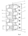
und - Fig. 3 eine perspektivische Ansicht einer geschnittenen Hartgeldzählrinne.
- 1 is a plan view of an embodiment of a hard money counter;
- Fig. 2 is an enlarged view of a portion of the coin counting trough shown in Fig. 1
and - Fig. 3 is a perspective view of a cut coin trough.
Die in Fig. 1 dargestellte Hartgeldzählrinne 1 entspricht in ihrem Grundaufbau der Hartgeldzählrinne, die in der DE-OS 34 04 486 beschrieben ist. Diese Hartgeldzählrinne 1 weist eine Achse 4 auf. Entlang dieser Achse 4 sind, gegeneinander versetzt, Münzfächer 2 angeordnet, die als offene Schiefzylindermulden ausgebildet sind. Diese Schiefzylindermulden weisen als Bestimmungsgrößen Grundkreise 3 der Schiefzylinder auf, deren Radius r bei der Herstellung der Hartgeldzählrinne 1 festliegt. Dieser Radius r entspricht dem Radius der Münze, die aufgenommen werden soll. Eine weitere feststehende Größe des als Schiefzylindermulde ausgebildeten Münzfaches 2 ist die Höhe h des Schiefzylinders. Die Verschiebung der beiden Schiefzylindergrundkreise 3 gegeneinander bestimmt die Richtung der Achse 10 der Münzfächer 2. Die Höhe h wird durch die Anzahl n der Münzen, die in jedem Münzfach 2 aufgenommen werden soll und deren Dicke bestimmt. h, n und r sind für die Fertigung der Hartgeldzählrinne festliegend.The basic structure of the
In Richtung der Achse 10 verläuft, wie die Fig. 2 zeigt, die tiefste Stelle eines jeden Münzfaches 2, die Münzfachbodenlinie 7.2, the deepest point of each
Wie Fig. 2 zeigt, erstreckt sich ein Abschnitt 6 der Innenwand 5 von der Münzfachbodenlinie 7 zum Rand 8 hin und bildet mit den benachbarten Münzfächern 2 offene Ränder 11. Dieser Abschnitt überquert die Achse 4 der Zählrinne 1. Zumindest dieser Abschnitt 6 der Innenwand 5 ist nicht glatt gestaltet sondern wird durch eine schräg gestaffelte Anordnung von Mantelflächenabschnitten 9 eines Zylinders gebildet. Durch diese gestaffelte Anordnung von Mantelflächenabschnitten 9 werden von Mantelflächenabschnitt zu Mantelflächenabschnitt Schultern 12 gebildet, die ihre maximale Höhe am Rand 8 des Münzfaches erreichen. Diese Höhe nimmt fortschreitend zur Münzfachbodenlinie 7 hin ab und erreicht dort den Wert Null.As shown in FIG. 2, a
Die Höhe eines jeden Mantelflächenabschnittes 9 wird durch die Höhe h, dividiert durch die Anzahl der Münzen n, bestimmt. Der Radius r dieser Mantelflächenabschnitte 9 entspricht dem Radius r der Grundkreise der die Münzfächer bildenden Schiefzylindermulden.The height of each
Wie die Fig. zeigen, sind die Abschnitte 6 in benachbarten Münzfächern 2 diametral gegenüberliegend angeordnet.As the figures show, the
Wenn lediglich eine einzige Münze in ein Münzfach 2 eingegeben ist, liegt deren Rand gegen die Schulter 12 dieses Münzfaches 2 an, die von der Achse 4 am weitesten entfernt ist. Diese Münze hat den Freiheitsgrad, sich beim Auftreten einer negativen Beschleunigung in einer vorbestimmten Richtung zu bewegen. Diese Bewegung ist eine Verschwenkung um die Schulter 12. Durch die Ausbildung des Abschnittes 6 der Innenwand 5 wird der Münzrand an der Schulter 12 festgehalten. Wenn der Abstand A zwischen dieser Schulter 12 und dem von der Achse 4 am weitesten entfernt liegenden Mantelflächenabschnitt 9 des in Beschleunigungsrichtung liegenden benachbarten Münzfaches 2 kleiner ist als 2r, schlägt die so bewegte Münze dort an und kann sich nicht weiter verschwenken. Die Münze kann nur eine vorbestimmte Verschwenkung durchführen, bleibt stehen und kann das Münzfach 2 nicht verlassen. Bei de geschilderten Schwenkbewegung handelt es sich um die maximal mögliche Schwenkbewegung. Je mehr Münzen im Münzfach 2 angeordnet sind, um so geringer wird die maximale Schwenkbewegung.If only a single coin is inserted into a
Claims (3)
1. je eine vorbestimmte Anzahl n gleichwertige Münzen aufnehmenden Münzfächern, die als
2. offene Schiefzylindermulden mit jeweils vorbestimmter Höhe h und vorbestimmtem Radius r des Grundkreises ausgebildet und
3. mit alternierend wechselnden Achsrichtungen
3.1 symmetrisch zur am Zählrinnenboden verlaufenden Achse der Zählrinne
3.1.1 seitlich gegeneinander versetzt, angeordnet sind,
dadurch gekennzeichnet, daß
4. zumindest der Abschnitt (6) der Innenwand (5) einer jeden Schiefzylindermulde (2),
4.1 der sich, ausgehend von der Münzfachbodenlinie (7) zum Rand (8) der Schiefzylindermulde erstreckt und
4.1.1 dabei die Achse (4) der Zählrinne (1) überquert und so mit benachbarten Schiefzylindermulden(2) die großen offenen Ränder (11) bildet,
5. aus n schräg gestaffelten Mantelflächenabschnitten (9) eines Zylinders gebildet ist, der
5.1 die Höhe h/n und den Radius r aufweist, und daß
6. die Richtung der Achse (10) der Schiefzylindermulde (2) und deren gegenseitige Versetzung so gewählt sind, daß, gemessen vom Rand (8) der Schiefzylindermulden (2) die Abstände (A) der jeweils von der Achse (4) der Zählrinne (1) am weitesten entfernt liegenden Mantelflächenabschnitte (9) aufeinanderfolgender Schiefzylindermulden (2) kleiner sind als der doppelte Radius 2r(A < 2r).1. Hartgeldzählrinne, especially for a money counting board, with
1. each a predetermined number n equivalent coins receiving coin compartments, which as
2. Open skew cylinder troughs with a predetermined height h and a predetermined radius r of the base circle are formed and
3. with alternating axial directions
3.1 symmetrical to the axis of the trough running on the bottom of the trough
3.1.1 laterally offset from one another, are arranged,
characterized in that
4. at least the section (6) of the inner wall (5) of each skew cylinder recess (2),
4.1 which, starting from the coin compartment floor line (7) to the edge (8) of the skew cylinder trough and
4.1.1 crosses the axis (4) of the counting trough (1) and thus forms the large open edges (11) with neighboring skew cylinder recesses (2),
5. from n obliquely staggered lateral surface sections (9) of a cylinder is formed
5.1 has the height h / n and the radius r, and that
6. The direction of the axis (10) of the skew cylinder trough (2) and their mutual displacement are chosen so that, measured from the edge (8) of the skew cylinder troughs (2), the distances (A) from the axis (4) of the counting trough (1) the most distant lateral surface sections (9) of successive skew cylinder recesses (2) are smaller than twice the radius 2r (A <2r).
dadurch gekennzeichnet, daß
4.2 die gesamte Innenwand (5) einer jeden Schiefzylindermulde (2) aus schräg gestaffelten Zylinder-Mantelflächenabschnitten (9) gebildet ist.2. coin counting trough according to claim 1,
characterized in that
4.2 the entire inner wall (5) of each oblique cylinder trough (2) is formed from obliquely staggered cylinder jacket surface sections (9).
dadurch gekennzeichnet, daß
7. in der ersten Schiefzylindermulde (2) für den Eingriff der ersten Münze eine Rille vorgesehen ist.3. Hartgeldzählrinne according to claim 1 or 2,
characterized in that
7. A groove is provided in the first skew cylinder recess (2) for the engagement of the first coin.
Priority Applications (1)
| Application Number | Priority Date | Filing Date | Title |
|---|---|---|---|
| AT89730162T ATE95619T1 (en) | 1988-08-29 | 1989-07-13 | CASH COUNTING CHUTTER. |
Applications Claiming Priority (2)
| Application Number | Priority Date | Filing Date | Title |
|---|---|---|---|
| DE3829597A DE3829597C1 (en) | 1988-08-29 | 1988-08-29 | |
| DE3829597 | 1988-08-29 |
Publications (3)
| Publication Number | Publication Date |
|---|---|
| EP0358596A2 true EP0358596A2 (en) | 1990-03-14 |
| EP0358596A3 EP0358596A3 (en) | 1990-05-02 |
| EP0358596B1 EP0358596B1 (en) | 1993-10-06 |
Family
ID=6362007
Family Applications (1)
| Application Number | Title | Priority Date | Filing Date |
|---|---|---|---|
| EP89730162A Expired - Lifetime EP0358596B1 (en) | 1988-08-29 | 1989-07-13 | Coin counting groove |
Country Status (9)
| Country | Link |
|---|---|
| EP (1) | EP0358596B1 (en) |
| AT (1) | ATE95619T1 (en) |
| DE (2) | DE3829597C1 (en) |
| DK (1) | DK411689A (en) |
| ES (1) | ES2045539T3 (en) |
| HU (1) | HU205215B (en) |
| PL (1) | PL161519B1 (en) |
| SU (1) | SU1766285A3 (en) |
| UA (1) | UA19852A (en) |
Cited By (2)
| Publication number | Priority date | Publication date | Assignee | Title |
|---|---|---|---|---|
| WO2004006192A2 (en) * | 2002-07-05 | 2004-01-15 | Emballage Conseil 2000 Inc. | Container for coins or tokens |
| EP1470763A1 (en) | 2003-04-23 | 2004-10-27 | Societe Novopac S.A. | Coin holder |
Families Citing this family (2)
| Publication number | Priority date | Publication date | Assignee | Title |
|---|---|---|---|---|
| FR2822031B1 (en) | 2001-05-18 | 2003-12-12 | Velfor Plast Sa | CONTAINER PACKAGE FOR COINS OR TOKENS |
| ES1238329Y (en) * | 2019-10-07 | 2020-02-26 | Munoz Juan Sanchez | COIN DRAWER |
Citations (2)
| Publication number | Priority date | Publication date | Assignee | Title |
|---|---|---|---|---|
| GB890195A (en) * | 1959-10-22 | 1962-02-28 | Margot Voss | Coin container |
| DE3404486A1 (en) * | 1984-02-06 | 1985-08-08 | Inkiess Margot Voss Gmbh, 1000 Berlin | Coin container |
Family Cites Families (1)
| Publication number | Priority date | Publication date | Assignee | Title |
|---|---|---|---|---|
| US3438479A (en) * | 1967-12-06 | 1969-04-15 | Robert A Bennett | Coin holder |
-
1988
- 1988-08-29 DE DE3829597A patent/DE3829597C1/de not_active Expired - Fee Related
-
1989
- 1989-07-13 AT AT89730162T patent/ATE95619T1/en not_active IP Right Cessation
- 1989-07-13 ES ES89730162T patent/ES2045539T3/en not_active Expired - Lifetime
- 1989-07-13 EP EP89730162A patent/EP0358596B1/en not_active Expired - Lifetime
- 1989-07-13 DE DE89730162T patent/DE58905828D1/en not_active Expired - Lifetime
- 1989-07-21 HU HU893706A patent/HU205215B/en unknown
- 1989-07-28 PL PL89280809A patent/PL161519B1/en unknown
- 1989-08-22 DK DK411689A patent/DK411689A/en not_active Application Discontinuation
- 1989-08-28 SU SU894614665A patent/SU1766285A3/en active
- 1989-08-28 UA UA4614665A patent/UA19852A/en unknown
Patent Citations (2)
| Publication number | Priority date | Publication date | Assignee | Title |
|---|---|---|---|---|
| GB890195A (en) * | 1959-10-22 | 1962-02-28 | Margot Voss | Coin container |
| DE3404486A1 (en) * | 1984-02-06 | 1985-08-08 | Inkiess Margot Voss Gmbh, 1000 Berlin | Coin container |
Cited By (3)
| Publication number | Priority date | Publication date | Assignee | Title |
|---|---|---|---|---|
| WO2004006192A2 (en) * | 2002-07-05 | 2004-01-15 | Emballage Conseil 2000 Inc. | Container for coins or tokens |
| WO2004006192A3 (en) * | 2002-07-05 | 2004-04-22 | Emballage Conseil 2000 Inc | Container for coins or tokens |
| EP1470763A1 (en) | 2003-04-23 | 2004-10-27 | Societe Novopac S.A. | Coin holder |
Also Published As
| Publication number | Publication date |
|---|---|
| PL161519B1 (en) | 1993-07-30 |
| ES2045539T3 (en) | 1994-01-16 |
| HU205215B (en) | 1992-03-30 |
| ATE95619T1 (en) | 1993-10-15 |
| EP0358596A3 (en) | 1990-05-02 |
| EP0358596B1 (en) | 1993-10-06 |
| DK411689A (en) | 1990-03-01 |
| HUT54818A (en) | 1991-03-28 |
| UA19852A (en) | 1997-12-25 |
| SU1766285A3 (en) | 1992-09-30 |
| DE3829597C1 (en) | 1990-03-08 |
| DK411689D0 (en) | 1989-08-22 |
| DE58905828D1 (en) | 1993-11-11 |
Similar Documents
| Publication | Publication Date | Title |
|---|---|---|
| EP0436496B1 (en) | Key for lock cylinder, especially of lock systems | |
| DE3913437C2 (en) | Coin sorter | |
| DE3603687C2 (en) | ||
| DE10113510B4 (en) | Roller cage, direct-acting guide device and roller screw, which uses the roller cage | |
| DE3032203C2 (en) | ||
| DE3419268C2 (en) | Coin dispenser | |
| DE3038158A1 (en) | FOLD-OUT GUIDE | |
| WO1986000541A1 (en) | Unit with assemblable game blocks | |
| DE1901305A1 (en) | Device for moving a thread to and fro in winding machines | |
| EP0377135B1 (en) | Key for a cylinder lock | |
| DE3420551A1 (en) | MATERIAL FOR STACKABLE CONTAINERS | |
| DE3314511A1 (en) | Key for lock cylinders | |
| EP0358596B1 (en) | Coin counting groove | |
| DE2854602C2 (en) | Cases for magnetic tape cassettes | |
| DE3119626A1 (en) | Flat key for cylinder locks | |
| EP1333136A1 (en) | Lock cylinder | |
| DE3836872A1 (en) | LOCKING DEVICE MADE OF FLAT KEY AND LOCKING CYLINDER | |
| DE2629634A1 (en) | DEVICE FOR SEPARATING AND ARRANGING COINS ETC. | |
| DE2361664C2 (en) | Traversing thread guide and traversing device | |
| DE1030727B (en) | Flat key for pin cylinder locks | |
| DD273139A5 (en) | HARTGELDZAEHLRINNE | |
| DE2208428C2 (en) | Rotary cam switch | |
| DE2058668C3 (en) | Fastener | |
| DE2556681A1 (en) | PERMUTATION LOCK | |
| CH355710A (en) | Flat key for pin cylinder locks |
Legal Events
| Date | Code | Title | Description |
|---|---|---|---|
| PUAI | Public reference made under article 153(3) epc to a published international application that has entered the european phase |
Free format text: ORIGINAL CODE: 0009012 |
|
| PUAL | Search report despatched |
Free format text: ORIGINAL CODE: 0009013 |
|
| AK | Designated contracting states |
Kind code of ref document: A2 Designated state(s): AT BE CH DE ES FR GB GR IT LI LU NL SE |
|
| AK | Designated contracting states |
Kind code of ref document: A3 Designated state(s): AT BE CH DE ES FR GB GR IT LI LU NL SE |
|
| 17P | Request for examination filed |
Effective date: 19900504 |
|
| RAP3 | Party data changed (applicant data changed or rights of an application transferred) |
Owner name: INKIESS MARGOT VOSS GMBH |
|
| RAP3 | Party data changed (applicant data changed or rights of an application transferred) |
Owner name: INKIESS MARGOT VOSS GMBH |
|
| 17Q | First examination report despatched |
Effective date: 19920826 |
|
| GRAA | (expected) grant |
Free format text: ORIGINAL CODE: 0009210 |
|
| AK | Designated contracting states |
Kind code of ref document: B1 Designated state(s): AT BE CH DE ES FR GB GR IT LI LU NL SE |
|
| REF | Corresponds to: |
Ref document number: 95619 Country of ref document: AT Date of ref document: 19931015 Kind code of ref document: T |
|
| REF | Corresponds to: |
Ref document number: 58905828 Country of ref document: DE Date of ref document: 19931111 |
|
| ITF | It: translation for a ep patent filed |
Owner name: BUGNION S.P.A. |
|
| GBT | Gb: translation of ep patent filed (gb section 77(6)(a)/1977) |
Effective date: 19931208 |
|
| REG | Reference to a national code |
Ref country code: ES Ref legal event code: FG2A Ref document number: 2045539 Country of ref document: ES Kind code of ref document: T3 |
|
| ET | Fr: translation filed | ||
| REG | Reference to a national code |
Ref country code: GR Ref legal event code: FG4A Free format text: 3010154 |
|
| PLBE | No opposition filed within time limit |
Free format text: ORIGINAL CODE: 0009261 |
|
| STAA | Information on the status of an ep patent application or granted ep patent |
Free format text: STATUS: NO OPPOSITION FILED WITHIN TIME LIMIT |
|
| 26N | No opposition filed | ||
| EPTA | Lu: last paid annual fee | ||
| EAL | Se: european patent in force in sweden |
Ref document number: 89730162.8 |
|
| PGFP | Annual fee paid to national office [announced via postgrant information from national office to epo] |
Ref country code: GB Payment date: 19960701 Year of fee payment: 8 Ref country code: LU Payment date: 19960701 Year of fee payment: 8 |
|
| PGFP | Annual fee paid to national office [announced via postgrant information from national office to epo] |
Ref country code: SE Payment date: 19960719 Year of fee payment: 8 |
|
| PGFP | Annual fee paid to national office [announced via postgrant information from national office to epo] |
Ref country code: BE Payment date: 19960723 Year of fee payment: 8 Ref country code: CH Payment date: 19960723 Year of fee payment: 8 |
|
| PGFP | Annual fee paid to national office [announced via postgrant information from national office to epo] |
Ref country code: GR Payment date: 19960725 Year of fee payment: 8 |
|
| PGFP | Annual fee paid to national office [announced via postgrant information from national office to epo] |
Ref country code: NL Payment date: 19960730 Year of fee payment: 8 |
|
| PG25 | Lapsed in a contracting state [announced via postgrant information from national office to epo] |
Ref country code: GB Free format text: LAPSE BECAUSE OF NON-PAYMENT OF DUE FEES Effective date: 19970713 Ref country code: LU Free format text: LAPSE BECAUSE OF NON-PAYMENT OF DUE FEES Effective date: 19970713 |
|
| PG25 | Lapsed in a contracting state [announced via postgrant information from national office to epo] |
Ref country code: SE Effective date: 19970714 |
|
| PG25 | Lapsed in a contracting state [announced via postgrant information from national office to epo] |
Ref country code: GR Free format text: LAPSE BECAUSE OF NON-PAYMENT OF DUE FEES Effective date: 19970731 Ref country code: LI Free format text: LAPSE BECAUSE OF NON-PAYMENT OF DUE FEES Effective date: 19970731 Ref country code: CH Free format text: LAPSE BECAUSE OF NON-PAYMENT OF DUE FEES Effective date: 19970731 Ref country code: BE Free format text: LAPSE BECAUSE OF NON-PAYMENT OF DUE FEES Effective date: 19970731 |
|
| BERE | Be: lapsed |
Owner name: INKIESS MARGOT VOSS G.M.B.H. Effective date: 19970731 |
|
| PG25 | Lapsed in a contracting state [announced via postgrant information from national office to epo] |
Ref country code: NL Free format text: LAPSE BECAUSE OF NON-PAYMENT OF DUE FEES Effective date: 19980201 |
|
| GBPC | Gb: european patent ceased through non-payment of renewal fee |
Effective date: 19970713 |
|
| REG | Reference to a national code |
Ref country code: CH Ref legal event code: PL |
|
| NLV4 | Nl: lapsed or anulled due to non-payment of the annual fee |
Effective date: 19980201 |
|
| EUG | Se: european patent has lapsed |
Ref document number: 89730162.8 |
|
| PG25 | Lapsed in a contracting state [announced via postgrant information from national office to epo] |
Ref country code: IT Free format text: LAPSE BECAUSE OF NON-PAYMENT OF DUE FEES;WARNING: LAPSES OF ITALIAN PATENTS WITH EFFECTIVE DATE BEFORE 2007 MAY HAVE OCCURRED AT ANY TIME BEFORE 2007. THE CORRECT EFFECTIVE DATE MAY BE DIFFERENT FROM THE ONE RECORDED. Effective date: 20050713 |
|
| PGFP | Annual fee paid to national office [announced via postgrant information from national office to epo] |
Ref country code: DE Payment date: 20080709 Year of fee payment: 20 Ref country code: ES Payment date: 20080723 Year of fee payment: 20 |
|
| PGFP | Annual fee paid to national office [announced via postgrant information from national office to epo] |
Ref country code: AT Payment date: 20080722 Year of fee payment: 20 Ref country code: FR Payment date: 20080718 Year of fee payment: 20 |
|
| PGRI | Patent reinstated in contracting state [announced from national office to epo] |
Ref country code: IT Effective date: 20090401 |
|
| PGFP | Annual fee paid to national office [announced via postgrant information from national office to epo] |
Ref country code: IT Payment date: 20080726 Year of fee payment: 20 |
|
| REG | Reference to a national code |
Ref country code: ES Ref legal event code: FD2A Effective date: 20090714 |
|
| PG25 | Lapsed in a contracting state [announced via postgrant information from national office to epo] |
Ref country code: ES Free format text: LAPSE BECAUSE OF EXPIRATION OF PROTECTION Effective date: 20090714 |