EP0358523B1 - Structures en forme de coupole et procédé pour les réaliser par moulage superplastique et soudage par diffusion - Google Patents
Structures en forme de coupole et procédé pour les réaliser par moulage superplastique et soudage par diffusion Download PDFInfo
- Publication number
- EP0358523B1 EP0358523B1 EP89309119A EP89309119A EP0358523B1 EP 0358523 B1 EP0358523 B1 EP 0358523B1 EP 89309119 A EP89309119 A EP 89309119A EP 89309119 A EP89309119 A EP 89309119A EP 0358523 B1 EP0358523 B1 EP 0358523B1
- Authority
- EP
- European Patent Office
- Prior art keywords
- sheets
- stack
- forming
- domed
- metallic bonds
- Prior art date
- Legal status (The legal status is an assumption and is not a legal conclusion. Google has not performed a legal analysis and makes no representation as to the accuracy of the status listed.)
- Expired - Lifetime
Links
Images


Classifications
-
- B—PERFORMING OPERATIONS; TRANSPORTING
- B21—MECHANICAL METAL-WORKING WITHOUT ESSENTIALLY REMOVING MATERIAL; PUNCHING METAL
- B21D—WORKING OR PROCESSING OF SHEET METAL OR METAL TUBES, RODS OR PROFILES WITHOUT ESSENTIALLY REMOVING MATERIAL; PUNCHING METAL
- B21D26/00—Shaping without cutting otherwise than using rigid devices or tools or yieldable or resilient pads, i.e. applying fluid pressure or magnetic forces
- B21D26/02—Shaping without cutting otherwise than using rigid devices or tools or yieldable or resilient pads, i.e. applying fluid pressure or magnetic forces by applying fluid pressure
- B21D26/053—Shaping without cutting otherwise than using rigid devices or tools or yieldable or resilient pads, i.e. applying fluid pressure or magnetic forces by applying fluid pressure characterised by the material of the blanks
- B21D26/055—Blanks having super-plastic properties
-
- B—PERFORMING OPERATIONS; TRANSPORTING
- B23—MACHINE TOOLS; METAL-WORKING NOT OTHERWISE PROVIDED FOR
- B23K—SOLDERING OR UNSOLDERING; WELDING; CLADDING OR PLATING BY SOLDERING OR WELDING; CUTTING BY APPLYING HEAT LOCALLY, e.g. FLAME CUTTING; WORKING BY LASER BEAM
- B23K20/00—Non-electric welding by applying impact or other pressure, with or without the application of heat, e.g. cladding or plating
-
- Y—GENERAL TAGGING OF NEW TECHNOLOGICAL DEVELOPMENTS; GENERAL TAGGING OF CROSS-SECTIONAL TECHNOLOGIES SPANNING OVER SEVERAL SECTIONS OF THE IPC; TECHNICAL SUBJECTS COVERED BY FORMER USPC CROSS-REFERENCE ART COLLECTIONS [XRACs] AND DIGESTS
- Y10—TECHNICAL SUBJECTS COVERED BY FORMER USPC
- Y10T—TECHNICAL SUBJECTS COVERED BY FORMER US CLASSIFICATION
- Y10T29/00—Metal working
- Y10T29/49—Method of mechanical manufacture
- Y10T29/49826—Assembling or joining
- Y10T29/49879—Spaced wall tube or receptacle
-
- Y—GENERAL TAGGING OF NEW TECHNOLOGICAL DEVELOPMENTS; GENERAL TAGGING OF CROSS-SECTIONAL TECHNOLOGIES SPANNING OVER SEVERAL SECTIONS OF THE IPC; TECHNICAL SUBJECTS COVERED BY FORMER USPC CROSS-REFERENCE ART COLLECTIONS [XRACs] AND DIGESTS
- Y10—TECHNICAL SUBJECTS COVERED BY FORMER USPC
- Y10T—TECHNICAL SUBJECTS COVERED BY FORMER US CLASSIFICATION
- Y10T428/00—Stock material or miscellaneous articles
- Y10T428/12—All metal or with adjacent metals
- Y10T428/1234—Honeycomb, or with grain orientation or elongated elements in defined angular relationship in respective components [e.g., parallel, inter- secting, etc.]
Definitions
- This invention relates to domed structures manufactured by a superplastic forming and diffusion bonding process. More particularly, it concerns deep domed structures of cellular construction and of regular or irregular form.
- the term 'domed structure' and like expressions means a structure having two (or more) opposed external surfaces one being generally convex, the other being generally concave.
- the domed structure will also have a peak on its convex surface, the structure sloping away from the peak in all directions, that is to say the peak is not formed as a straight ridge; likewise, the concave surface is not formed by a straight furrow.
- the domed structure can be regular in shape, e.g.
- a hemisphere or a hemi-elipsoid or it can be irregular; the peak need not be a point but rather can be a general area at the top of the dome.
- the term 'domed structure' also includes structures in which the dome forms only a part of a larger structure, the remainder having any desired shape.
- Metals having superplastic characteristics have a composition and micro-structure such that when heated to within an appropriate temperature range and when deformed at a strain rate within an appropriate range they exhibit the flow characteristics of a viscous fluid. With such metals, large deformations are possible without fracture.
- Diffusion bonding is a process by which a metallurgical bond is formed by the application of heat and pressure to metallic pieces held in close contact for a specific length of time. Bonding is thought to occur by the movement of atoms across adjacent faces of the pieces. The process allows metals to be joined without significantly changing their physical or metallurgical properties.
- the temperature ranges at which superplasticity and diffusion bonding occur may or may not be the same depending upon the material joined.
- GB-A- a method of forming a stiffened panel is taught in which an interior sheet is placed between two face sheets and the inner faces of each of the face sheets are attached directly to the respectively adjacent faces of the interior sheet by metallurgically bonded regions. At least the interior sheet is of superplastic material.
- the blank sheets are welded around their assembled peripheries to form a sealed envelope which is fed internally with a pressurised inert gas such that when the interior sheet is superplastic the outer sheets are moved apart by a predetermined amount to effect corrugation of the interior sheet thus effectively achieving a cellular structure of 'zig-zag' construction.
- twin interior sheets forming a sealed envelope and being joined to each other by metallurgically bonded regions are supplied with inert gas under pressure, thereby causing the sheets to serve away from each other within a limiting fixture, which may include face sheets, the envelope being expanded against the face sheets to form a series of cavities between the sheets, the said cavities being preferably of substantially rectangular form.
- US-A-4,526,312 teaches a method of making metallic sandwich structure by superplastic forming and diffusion bonding using a three sheet stack assembly of blanks but whereas in the previous examples of prior art the expanded assembly remains substantially flat, in this example the sandwich structure is required to achieve single curvature configuration, that is to say the structure has a straight ridge along an external face.
- the flat stack is placed in a mould and simultaneously or sequentially formed to a desired curvature; it is then trimmed and the trimmed stack is placed in a further mould defining the boundaries of the required component form and then formed into the expanded sandwich structure.
- the corrugations or 'zig-zag' stiffeners lie transversely to the radius of curvature, i.e.the stiffeners lie parallel to the ridge. Such a process cannot, however, be used for forming domed structures.
- US-A-4 304 821 describes a method of making a panel of cellular construction having two face sheets and at least one core sheet by superplastically expanding the one or more core sheets within a cavity formed by the face sheets that are held spaced apart in a fixture.
- the core sheet(s) are welded to each other or to a face sheet before superplastic forming.
- GB-A-1 495 655 describes a method of forming a planar panel of cellular construction by superplastically expanding a stack of sheets within a mould cavity; the sheets are welded together in the stack prior to superplastic forming.
- a method of manufacturing a domed cellular metallic structure comprising a convex surface having a peak and a concave surface opposed to the convex surface, which method is as defined in the accompanying claims 1-7.
- the present invention also provides a domed structure as defined in the accompanying claims 8-11.
- Figure 1 shows a four sheet lay up; two interior sheets 10 are placed between two outer (or face) sheets 11 and 12 to form a stack 19.
- the interior sheets 10 are metallurgically bonded together at 13 but are not bonded to outer sheets 11 and 12.
- the position of the bonds is shown in Figure 13 and, as can be seen, the bonds 13 are formed along lines running radially and circumferentially with respect to a point (or area) 20 which will form the peak of the desired domed structure.
- the bonds 13 need not be formed continuously all the way along the lines indicated and indeed, as indicated below, preferably they are not continuous; suitable point bonds formed along the indicated lines will be satisfactory.
- the metallurgical bonds indicated may be resistance welds, electron beam welds or diffusion bonds and may be of line or spot form in accordance with requirements.
- the four sheets 10, 11 and 12 are circular in order to make a dome of circular plan and are made of superplastic material, that is to say material that when heated to a suitable temperature exhibits superplastic properties.
- FIG 5 a three sheet arrangement is illustrated in which a superplastic interior sheet 14 is sandwiched between two superplastic face sheets 16 and 17 to form a stack 19.
- the interior sheet 14 is metallurgically bonded to the lower face sheet 17 as shown by bonds 13, the positions of which are the same as in the four sheet arrangement, i.e. as shown in Figure 13. Sheets 14 and 16 are not joined joined together.
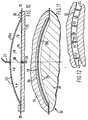
- Figures 2 to 4 Three examples of methods of producing a cellular domed structure in accordance with the invention are illustrated in connection with Figures 2 to 4 (illustrating the structure achieved with the four sheet lay up of Figure 1), Figures 6 to 8 (illustrating the structure achieved with the three sheet lay up of Figure 5) and Figures 10 to 12 (illustrating the structure achieved with the two sheet lay up of Figure 9).
- Figures 2 to 4 Three examples of methods of producing a cellular domed structure in accordance with the invention are illustrated in connection with Figures 2 to 4 (illustrating the structure achieved with the four sheet lay up of Figure 1), Figures 6 to 8 (illustrating the structure achieved with the three sheet lay up of Figure 5) and Figures 10 to 12 (illustrating the structure achieved with the two sheet lay up of Figure 9).
- the optimum cellular structure that is chosen in practice will be determined by structural requirements.
- the circular stack 19 (shown in ghost lines) composed of two, three or four sheets is placed in a sealed platen fixture 25 to which it is secured by means of a peripheral clamp 26.
- a cut out switch 27 is located above the platen coincident with the centre line 28 and at a height corresponding to the desired dome height.
- the peripheral edge 30 of the blank assembly is TIG (tungsten inert gas) welded to form a sealed envelope and further incorporated into the edge are twin gas inlet ports 21 (see Figure 13) for the supply of inert gas under pressure to the interspaces between the respective sheets that are connected by bonds 13.
- the process is free blown and the pressure will be cut off as the inflated envelope comes into contact with a cut out switch 27.
- the dome may be achieved by blowing into a female mould or template.
- gas is injected through the gas inlet ports 21 at a pressure that is just sufficient to initiate a slight expansion of the envelope (i.e. the pressure is insufficient to cause complete superplastic forming); this gas pressure maintains a small separation between the sheets during formation of the dome and so serves to deter diffusion bonding between abutting faces of the sheets.
- Diffusion bonding between sheets that are joined by bonds 13 can also be prevented by the application of a known stopping-off composition to the interface between these sheets but such a remedy is not available to prevent diffusion bonding in other interfaces in the stack 19 because such measures would also prevent diffusion bonding at a later stage of the process when it is necessary to bring about diffusion bonding at these other interfaces (see below) in order to form a stiff, unified domed structure. Deleterious diffusion bonding may be avoided in these cases by forming the dome at a temperature lower than that at which diffusion bonding will occur.
- a forming mould tool 32 (see Figures 3, 7 and 11) which comprises a lower male tool 33 and an upper female tool 34, the male tool having a convex domed surface 35 and the female tool a concave surface 36 of inverted form configured such that when they are assembled around the domed component 19a they form a parallel sided cavity having a depth corresponding to the required cellular structure.
- the domed component 19a is peripherally clamped within the mould tool assembly 32 and the whole is heated to within a temperature range at which the component sheets exhibit superplastic characteristics.
- An inert gas e.g. argon
- the bonds 13 are preferably not formed continuously all the way along the lines shown in Figure 13, but rather are interupted by unbonded gaps that allow the inert gas from inlet tubes 21 to pass through them to reach all areas of the blank 19.
- the inert gas causes the stack to be superplastically formed into the shape of the mould cavity as described below.
- the inert gas is fed into the interspace between the two sheets 22 and 23 and inflates the sheets about bonds 13 until the portions 38 of these sheets conform to the surfaces 35 and 36 of the mould.
- Such a structure will have webs 40 formed by bent-back portions 39 of the sheets 23 and 24.
- the blank 19 may be of irregular plan form and the method of forming may be adopted to produce a component having an irregular outer profile 43 and a different inner irregular profile 44 as shown in Figures 16 and 17.
- the blank may (as in the previously described embodiment) be free blown within the bounds of the clamping fixture 40 and the limiting block 41 (or cut-out switch) but the stack may simultaneously be partly expanded as shown. This partially expanded component is then clamped within a mould tool assembly 45 having appropriately shaped upper and lower mould surfaces 46 and 47 then further expanded to attain the structure of Figure 13.
- the dome may not have a precisely defined peak but rather it may have a general peak area in which case the bonds 13 (see Figure 13) will extend generally around the peak area and/or extend radially therefrom.
- the peak thus need not be a point and it could be a flat plateau at the top of the dome.
- the circumferentially extending metallic bonds need not be circular in shape but could be composed of a number of straight lines.
- attachment faces angularly disposed to the forming plane to be formed as an integral part of the domed structure and which may, for instance, in the case of an aircraft pressure bulkhead be utilised for attachment to fuselage skin panels.
- Figure 18 One example is illustrated in Figure 18 in which the domed structure is formed with an integral attachment face 48 as an extension of the peripheral clamping flange 49, the clamping flange 49 being removed along a trim line 50 on completion of production.
- the attachment face is shown at right-angles to the clamping face, it may be inclined where it has to conform to a tapering fuselage profile, for example.
Claims (11)
- Procédé de fabrication d'une structure métallique cellulaire, le procédé comprenant les étapes consistant à :(A) Fournir au moins deux tôles métalliques (10, 11, 12; 14, 16, 17; 22, 23) ayant des caractéristiques superplastiques;(B) Réunir deux desdites tôles en contact face à face par des liaisons ou des soudures métalliques (13) et former les tôles en empilage (19) de façon qu'aucune des tôles ainsi réunies ne soit en outre réunie à une autre tôle de l'empilage;(C) Rendre étanches les bords périmètriques (30) du dit empilage (19) mais comprenant un moyen (21) pour l'admission d'un gaz inerte pressurisé entre lesdites tôles, d'où la formation d'une enveloppe gonflable;(D) Ouvrir un outil de moulage (32) ayant des surfaces supérieure et inférieure opposées (35, 36) qui définissent une cavité et placer ledite empilage (19a) dans la cavité; et(E) Chauffer ledit empilage (19a) et ledit outil de moulage (32) à une température appropriée à une formation superplastique et à une liaison par diffusion, fournir du gaz inerte sous pression entre lesdites tôles, d'où l'expansion par formage superplastique des tôles les plus à l'extérieur (10, 12; 16, 17; 22, 23) du dit empilage (19a) pour épouser la forme des surfaces supérieure et inférieure (35, 36) du dit outil de moulage et en outre amener lesdites tôles à s'étendre autour desdites liaisons métalliques pour former des voiles (39) s'étendant entre les tôles les plus à l'extérieur, d'où la définition d'une structure cellulaire;
caractérisé en ce que, dans le but de fabriquer une structure métallique cellulaire en dôme comportant une surface convexe ayant une crête et une surface concave opposée à la surface convexe, le procédé comprend en outre les étapes suivantes entre les étapes (C) et (D) :(C1) Placer ledit empilage dans un montage (25) comportant un moyen (26) pour fixer de manière étanche ledit empilage (19) à l'intérieur du dit montage au droit ou autour de son périmètre et un moyen (31) pour l'admission d'une fourniture de gaz inerte pressurisé à une face externe du dit empilage (19);(C2) Chauffer ledit empilage (19) et ledit montage (25) à une température permettant le formage superplastique, appliquer le gaz pressurisé à ladite face externe du dit empilage (19) de façon que l'empilage se détente de façon superplastique pour prendre la forme en dôme pré-définie (19a); et
caractérisé en outre en ce que lesdites surfaces supérieure et inférieure du dit outil de moulage forment une cavité en dôme, d'où il résulte que dans l'étape (E) les tôles les plus à l'extérieur (10, 12; 16, 17; 22, 23) du dit empilage en dôme (19a) se détentent de manière superplastique pour épouser les surfaces supérieure et inférieure (35, 36) du dit outil de moulage afin de former lesdites surfaces convexe et concave de la structure en dôme. - Procédé selon la revendication 1, caractérisé en ce qu'on fournit deux tôles métalliques (22, 23) et en ce que les deux tôles sont réunies dans un contact face à face par lesdites liaisons métalliques.
- Procédé selon la revendication 1, caractérisé en ce qu'on fournit trois tôles métalliques (14, 16, 17) qui sont formées en un empilage (19) ayant deux tôles extérieures (16, 17) et une tôle interne (14) intercalée entre les tôles extérieures, et dans lequel la tôle interne (14) n'est réunie qu'à l'une des tôles extérieures (17) par lesdites liaisons métalliques (13).
- Procédé selon la revendication 1, caractérisé en ce qu'on fournit quatre tôles métalliques (10, 10, 11, 12) qui sont formées en un empilage (19) ayant deux tôles extérieures (11, 12) et deux tôles internes (10, 10) intercalées entre les tôles extérieures et dans lequel les tôles internes sont réunies ensemble par lesdites liaisons métalliques (13).
- Procédé selon l'une quelconques des revendications 1 à 4, caractérisé en ce que les liaisons métalliques (13) sont situées sur des lignes s'étendant radialement à partir de ladite crête (20) et/ou circonférentiellement autour de cette crête.
- Procédé selon la revendication 5, caractérisé en ce que lesdites liaisons ou soudures métalliques s'étendant circonférentiellement sont des cercles qui sont espacés concentriquement les uns des autres autour d'un point et dans lequel les liaisons ou soudures métalliques s'étendant radialement s'étendent radialement pour s'éloigner de ce point, point qui forme la crête (20) de la structure finale en dôme.
- Procédé selon l'une quelconque des revendications 1 à 6, caractérisé en ce qu'il comporte l'étape consistant à injecter du gaz inerte entre les tôles pendant ladite étape (C2) dans laquelle du gaz pressurisé est appliqué à une face externe du dit empilage.
- Structure métallique en dôme constituée de deux tôles ou plus (10, 11, 12; 14, 16, 17; 22, 23) en métal superplastique, la structure comportant :. une surface convexe ayant une crête (20),. une surface concave qui est opposée à ladite surface convexe,. des voiles (39) s'étendant entre les surfaces convexe et concave, d'où la formation d'une partie centrale cellulaire à l'intérieur de la structure en dôme, voiles qui sont constitués de portions de deux desdites tôles qui sont réunies par des liaisons métalliques (13),
caractérisé en ce que les liaisons métalliques (13) sont situées sur des lignes s'étendant radialement à partir de ladite crête (20) et/ou circonférentiellement autour de celle-ci. - Structure selon la revendication 8, caractérisée en ce qu'elle est constituée de deux tôles (22, 23), une première des tôles (22) formant la surface convexe et une partie de chacun desdits voiles (39) et la seconde desdites tôles (23) formant la surface concave et le reste desdits voiles (39), les voiles étant constitués chacun d'une portion de la première tôle qui a été repliée sur elle-même pour former une nervure et une portion de la seconde tôle qui a été également repliée sur elle-même pour former un nervure, les deux portions étant réunies le long desdites nervures par lesdites liaisons métalliques (13).
- Structure selon la revendication 8, caractérisée en ce qu'elle est constituée de trois tôles (14, 16, 17), une première des tôles (16) formant la surface convexe et une seconde des tôles (17) formant la surface concave et dans lequel lesdits voiles (39) sont chacun formés en partie par une portion de l'une desdites première et seconde tôles qui a été repliée sur elle-même pour former une nervure et en partie par une portion d'une troisième desdites tôles (14) qui a été repliée sur elle-même pour former une nervure, les deux portions étant réunies le long desdites nervures par lesdites liaisons métalliques (13).
- Structure selon la revendication 8, caractérisée en ce qu'elle est constituée de quatre tôles (10, 10, 11, 12), une première desdites tôles (11) formant la surface convexe et une seconde desdites tôles (12) formant la surface concave et dans laquelle chacun desdits voiles est formé en partie par une portion d'une troisième desdits voiles (10) qui a été repliée sur elle-même pour former une nervure et en partie par une portion d'une quatrième desdites tôles (10) qui a été repliée sur elle-même pour former une nervure, les deux portions étant réunies le long desdites nervures par lesdites liaisons métalliques (13).
Applications Claiming Priority (2)
| Application Number | Priority Date | Filing Date | Title |
|---|---|---|---|
| GB8821222 | 1988-09-09 | ||
| GB888821222A GB8821222D0 (en) | 1988-09-09 | 1988-09-09 | Double curvature structures by superplastic forming & diffusion bonding |
Publications (2)
| Publication Number | Publication Date |
|---|---|
| EP0358523A1 EP0358523A1 (fr) | 1990-03-14 |
| EP0358523B1 true EP0358523B1 (fr) | 1993-06-23 |
Family
ID=10643357
Family Applications (1)
| Application Number | Title | Priority Date | Filing Date |
|---|---|---|---|
| EP89309119A Expired - Lifetime EP0358523B1 (fr) | 1988-09-09 | 1989-09-08 | Structures en forme de coupole et procédé pour les réaliser par moulage superplastique et soudage par diffusion |
Country Status (6)
| Country | Link |
|---|---|
| US (1) | US5143276A (fr) |
| EP (1) | EP0358523B1 (fr) |
| JP (1) | JP2561348B2 (fr) |
| DE (1) | DE68907299T2 (fr) |
| ES (1) | ES2041416T3 (fr) |
| GB (1) | GB8821222D0 (fr) |
Families Citing this family (41)
| Publication number | Priority date | Publication date | Assignee | Title |
|---|---|---|---|---|
| US5385204A (en) * | 1989-08-25 | 1995-01-31 | Rolls-Royce Plc | Heat exchanger and methods of manufacture thereof |
| US5193737A (en) * | 1989-10-12 | 1993-03-16 | General Electric Company | Method and apparatus for diffusion bonding |
| US5287918A (en) * | 1990-06-06 | 1994-02-22 | Rolls-Royce Plc | Heat exchangers |
| US5505256A (en) * | 1991-02-19 | 1996-04-09 | Rolls-Royce Plc | Heat exchangers and methods of manufacture thereof |
| US5118026A (en) * | 1991-04-05 | 1992-06-02 | Rockwell International Corporation | Method for making titanium aluminide metallic sandwich structures |
| GB9121107D0 (en) * | 1991-10-04 | 1991-11-20 | British Aerospace | Improvements relating to diffusion bonded/superplastically formed cellular structures |
| US5330092A (en) * | 1991-12-17 | 1994-07-19 | The Boeing Company | Multiple density sandwich structures and method of fabrication |
| GB9425447D0 (en) * | 1994-12-16 | 1995-02-15 | British Aerospace | Superplastically formed structure |
| GB9425461D0 (en) * | 1994-12-16 | 1995-02-15 | British Aerospace | Superplastically formed panel |
| US5655702A (en) * | 1995-04-19 | 1997-08-12 | Aerojet-General Corporation | Sacrificial bonding and forming aid for platelet assemblies |
| US5651850A (en) * | 1996-01-11 | 1997-07-29 | The Boeing Company | Method of fabricating hybrid composite structures |
| US5700347A (en) * | 1996-01-11 | 1997-12-23 | The Boeing Company | Thermoplastic multi-tape application head |
| US5866272A (en) * | 1996-01-11 | 1999-02-02 | The Boeing Company | Titanium-polymer hybrid laminates |
| US6039832A (en) * | 1998-02-27 | 2000-03-21 | The Boeing Company | Thermoplastic titanium honeycomb panel |
| ES2181512B1 (es) * | 1999-06-15 | 2004-05-16 | Mecanizaciones Aeronauticas, S.A. | Procedimiento de fabricacion de elementos tridimensionales en materiales metalicos. |
| US6213426B1 (en) | 1999-07-09 | 2001-04-10 | The Boeing Company | Monolithic structure with redundant load paths |
| GB0006734D0 (en) | 2000-03-20 | 2000-05-10 | British Aerospace | Superplastic forming method |
| GB0021936D0 (en) * | 2000-09-07 | 2000-10-25 | Newby Stephen J | Metal cushions |
| US7197852B2 (en) * | 2002-09-20 | 2007-04-03 | The Boeing Company | Internally stiffened composite panels and methods for their manufacture |
| JP2004251428A (ja) * | 2003-02-21 | 2004-09-09 | Toshiba Home Technology Corp | 断熱体の製造方法 |
| US7104306B2 (en) | 2004-06-14 | 2006-09-12 | The Boeing Company | Cast unitized primary truss structure and method |
| US7431196B2 (en) * | 2005-03-21 | 2008-10-07 | The Boeing Company | Method and apparatus for forming complex contour structural assemblies |
| US7766277B2 (en) * | 2006-01-19 | 2010-08-03 | The Boeing Company | Deformable forward pressure bulkhead for an aircraft |
| GB2450934B (en) | 2007-07-13 | 2009-10-07 | Rolls Royce Plc | A Component with a damping filler |
| GB2450935B (en) * | 2007-07-13 | 2009-06-03 | Rolls Royce Plc | Component with internal damping |
| GB0808840D0 (en) | 2008-05-15 | 2008-06-18 | Rolls Royce Plc | A compound structure |
| GB2462102B (en) | 2008-07-24 | 2010-06-16 | Rolls Royce Plc | An aerofoil sub-assembly, an aerofoil and a method of making an aerofoil |
| GB0901235D0 (en) | 2009-01-27 | 2009-03-11 | Rolls Royce Plc | An article with a filler |
| GB0901318D0 (en) | 2009-01-28 | 2009-03-11 | Rolls Royce Plc | A method of joining plates of material to form a structure |
| GB201009216D0 (en) | 2010-06-02 | 2010-07-21 | Rolls Royce Plc | Rotationally balancing a rotating part |
| GB2485831B (en) | 2010-11-26 | 2012-11-21 | Rolls Royce Plc | A method of manufacturing a component |
| US8844796B1 (en) | 2013-03-05 | 2014-09-30 | The Boeing Company | Superplastically formed ultrasonically welded metallic structure |
| US10189578B2 (en) * | 2013-06-12 | 2019-01-29 | The Boeing Company | Self-balancing pressure bulkhead |
| US9446483B2 (en) * | 2015-02-11 | 2016-09-20 | The Boeing Company | Dual walled titanium tubing and methods of manufacturing the tubing |
| US10941455B2 (en) * | 2016-05-25 | 2021-03-09 | The Boeing Company | Sandwich structure and associated pressure-based forming method |
| EP3446804A1 (fr) | 2017-08-22 | 2019-02-27 | BAE SYSTEMS plc | Formage superplastique et procédé de liaison par diffusion |
| WO2019038516A1 (fr) * | 2017-08-22 | 2019-02-28 | Bae Systems Plc | Procédé de formation superplastique et de liaison par diffusion |
| EP3446805A1 (fr) | 2017-08-22 | 2019-02-27 | BAE SYSTEMS plc | Formage superplastique et procédé de liaison par diffusion |
| US10807143B2 (en) | 2018-04-02 | 2020-10-20 | Rohr, Inc | Tooling for forming nacelle components |
| CN112570538A (zh) * | 2020-10-27 | 2021-03-30 | 航天材料及工艺研究所 | 一种橡皮垫料辅助铝锂合金薄壁结构蠕变时效成形工装 |
| CN112570537B (zh) * | 2020-10-27 | 2022-11-11 | 航天材料及工艺研究所 | 一种橡皮垫料辅助铝合金薄壁构件蠕变时效精密成形方法 |
Family Cites Families (13)
| Publication number | Priority date | Publication date | Assignee | Title |
|---|---|---|---|---|
| US3024525A (en) * | 1957-08-28 | 1962-03-13 | Goodyear Aircraft Corp | Method of making multi-walled concavo-convex objects |
| FR2131863B1 (fr) * | 1971-03-31 | 1974-09-27 | France Etat | |
| GB1429054A (en) * | 1973-07-24 | 1976-03-24 | British Aircraft Corp Ltd | Forming of metal panels |
| GB1495655A (en) * | 1975-03-20 | 1977-12-21 | Rockwell International Corp | Method for making metallic structures from two or more selectively bonded sheets |
| US4045986A (en) * | 1976-04-05 | 1977-09-06 | T.I. Superform | Forming ductile materials |
| US4217397A (en) * | 1978-04-18 | 1980-08-12 | Mcdonnell Douglas Corporation | Metallic sandwich structure and method of fabrication |
| US4304821A (en) * | 1978-04-18 | 1981-12-08 | Mcdonnell Douglas Corporation | Method of fabricating metallic sandwich structure |
| GB2030480B (en) * | 1978-09-29 | 1982-08-04 | British Aerospace | Method of making a stiffened panel |
| US4526312A (en) * | 1979-12-10 | 1985-07-02 | Rockwell International Corporation | Low cost method of making superplastically formed and diffusion bonded structures |
| DE3104919A1 (de) * | 1980-02-15 | 1981-12-17 | British Aerospace Public Ltd. Co., London | Verfahren zur herstellung von metallgegenstaenden |
| US4420958A (en) * | 1980-05-12 | 1983-12-20 | Rockwell International Corporation | Method and apparatus for regulating preselected loads on forming dies |
| GB8411611D0 (en) * | 1984-05-05 | 1984-06-13 | British Aerospace | Superplastic forming of panels |
| US4833768A (en) * | 1988-04-28 | 1989-05-30 | Mcdonnell Douglas Corporation | Curved SPF/DB sandwich fabrication |
-
1988
- 1988-09-09 GB GB888821222A patent/GB8821222D0/en active Pending
-
1989
- 1989-09-08 ES ES198989309119T patent/ES2041416T3/es not_active Expired - Lifetime
- 1989-09-08 DE DE89309119T patent/DE68907299T2/de not_active Expired - Fee Related
- 1989-09-08 EP EP89309119A patent/EP0358523B1/fr not_active Expired - Lifetime
- 1989-09-08 JP JP1234522A patent/JP2561348B2/ja not_active Expired - Fee Related
-
1991
- 1991-04-19 US US07/688,100 patent/US5143276A/en not_active Expired - Lifetime
Also Published As
| Publication number | Publication date |
|---|---|
| JPH02147124A (ja) | 1990-06-06 |
| EP0358523A1 (fr) | 1990-03-14 |
| GB8821222D0 (en) | 1988-12-14 |
| DE68907299D1 (de) | 1993-07-29 |
| DE68907299T2 (de) | 1993-09-30 |
| ES2041416T3 (es) | 1993-11-16 |
| JP2561348B2 (ja) | 1996-12-04 |
| US5143276A (en) | 1992-09-01 |
Similar Documents
| Publication | Publication Date | Title |
|---|---|---|
| EP0358523B1 (fr) | Structures en forme de coupole et procédé pour les réaliser par moulage superplastique et soudage par diffusion | |
| US4351470A (en) | Method of making a stiffened panel | |
| US4304821A (en) | Method of fabricating metallic sandwich structure | |
| US4217397A (en) | Metallic sandwich structure and method of fabrication | |
| US5534354A (en) | Multiple density sandwich structures | |
| US5243758A (en) | Design and processing method for manufacturing hollow airfoils (three-piece concept) | |
| US5692881A (en) | Hollow metallic structure and method of manufacture | |
| EP0414731B1 (fr) | Structure en sandwich courbes a formage superplastique/liaison par diffusion | |
| US5723225A (en) | Superplastically formed, diffusion bonded multiple sheet panels with web doublers and method of manufacture | |
| EP0928234B1 (fr) | Liaison par diffusion de metaux | |
| US5881459A (en) | Pressure communication for superplastically formed, diffusion bonded panels and method of manufacture | |
| US5715644A (en) | Superplastically formed, diffusion bonded panels with diagonal reinforcing webs and method of manufacture | |
| EP0161892B1 (fr) | Fabrication de panneaux renforcés | |
| US4588651A (en) | Accordion expansion process | |
| US4607783A (en) | Stiffened panel with apertures | |
| US4509671A (en) | Method of producing diffusion bonded superplastically formed structures | |
| US5300367A (en) | Metallic structural panel and method of fabrication | |
| US4577798A (en) | Method of fabricating expanded sandwich panels having an enclosed core | |
| US6279812B1 (en) | Method for producing rotational-symmetrical articles of sheet metal with double curved surface and varying thickness of material | |
| US4582244A (en) | Curved core sandwich structure forming method | |
| GB2129340A (en) | Stiffened panel | |
| US5809737A (en) | Structural parts for use in aircraft | |
| US4916928A (en) | Stops for curved SPF/DB sandwich fabrication | |
| GB2273256A (en) | Superplastic formed hollow components | |
| EP1268098B1 (fr) | Procede de formage superplastique et article tridimensionel realise par deformation superplastique |
Legal Events
| Date | Code | Title | Description |
|---|---|---|---|
| PUAI | Public reference made under article 153(3) epc to a published international application that has entered the european phase |
Free format text: ORIGINAL CODE: 0009012 |
|
| AK | Designated contracting states |
Kind code of ref document: A1 Designated state(s): DE ES FR GB IT NL SE |
|
| 17P | Request for examination filed |
Effective date: 19900903 |
|
| 17Q | First examination report despatched |
Effective date: 19911118 |
|
| RAP3 | Party data changed (applicant data changed or rights of an application transferred) |
Owner name: BRITISH AEROSPACE PUBLIC LIMITED COMPANY |
|
| GRAA | (expected) grant |
Free format text: ORIGINAL CODE: 0009210 |
|
| ITF | It: translation for a ep patent filed |
Owner name: BARZANO' E ZANARDO ROMA S.P.A. |
|
| AK | Designated contracting states |
Kind code of ref document: B1 Designated state(s): DE ES FR GB IT NL SE |
|
| ET | Fr: translation filed | ||
| REF | Corresponds to: |
Ref document number: 68907299 Country of ref document: DE Date of ref document: 19930729 |
|
| REG | Reference to a national code |
Ref country code: ES Ref legal event code: FG2A Ref document number: 2041416 Country of ref document: ES Kind code of ref document: T3 |
|
| PLBE | No opposition filed within time limit |
Free format text: ORIGINAL CODE: 0009261 |
|
| STAA | Information on the status of an ep patent application or granted ep patent |
Free format text: STATUS: NO OPPOSITION FILED WITHIN TIME LIMIT |
|
| 26N | No opposition filed | ||
| EAL | Se: european patent in force in sweden |
Ref document number: 89309119.9 |
|
| NLT1 | Nl: modifications of names registered in virtue of documents presented to the patent office pursuant to art. 16 a, paragraph 1 |
Owner name: BAE SYSTEMS PLC |
|
| REG | Reference to a national code |
Ref country code: GB Ref legal event code: IF02 |
|
| PGFP | Annual fee paid to national office [announced via postgrant information from national office to epo] |
Ref country code: FR Payment date: 20050815 Year of fee payment: 17 |
|
| PGFP | Annual fee paid to national office [announced via postgrant information from national office to epo] |
Ref country code: GB Payment date: 20050817 Year of fee payment: 17 |
|
| PGFP | Annual fee paid to national office [announced via postgrant information from national office to epo] |
Ref country code: DE Payment date: 20050818 Year of fee payment: 17 Ref country code: NL Payment date: 20050818 Year of fee payment: 17 |
|
| PGFP | Annual fee paid to national office [announced via postgrant information from national office to epo] |
Ref country code: SE Payment date: 20050824 Year of fee payment: 17 |
|
| PGFP | Annual fee paid to national office [announced via postgrant information from national office to epo] |
Ref country code: ES Payment date: 20050905 Year of fee payment: 17 |
|
| PG25 | Lapsed in a contracting state [announced via postgrant information from national office to epo] |
Ref country code: SE Free format text: LAPSE BECAUSE OF NON-PAYMENT OF DUE FEES Effective date: 20060909 |
|
| PGFP | Annual fee paid to national office [announced via postgrant information from national office to epo] |
Ref country code: IT Payment date: 20060930 Year of fee payment: 18 |
|
| PG25 | Lapsed in a contracting state [announced via postgrant information from national office to epo] |
Ref country code: NL Free format text: LAPSE BECAUSE OF NON-PAYMENT OF DUE FEES Effective date: 20070401 |
|
| PG25 | Lapsed in a contracting state [announced via postgrant information from national office to epo] |
Ref country code: DE Free format text: LAPSE BECAUSE OF NON-PAYMENT OF DUE FEES Effective date: 20070403 |
|
| EUG | Se: european patent has lapsed | ||
| GBPC | Gb: european patent ceased through non-payment of renewal fee |
Effective date: 20060908 |
|
| NLV4 | Nl: lapsed or anulled due to non-payment of the annual fee |
Effective date: 20070401 |
|
| REG | Reference to a national code |
Ref country code: FR Ref legal event code: ST Effective date: 20070531 |
|
| PG25 | Lapsed in a contracting state [announced via postgrant information from national office to epo] |
Ref country code: GB Free format text: LAPSE BECAUSE OF NON-PAYMENT OF DUE FEES Effective date: 20060908 |
|
| REG | Reference to a national code |
Ref country code: ES Ref legal event code: FD2A Effective date: 20060909 |
|
| PG25 | Lapsed in a contracting state [announced via postgrant information from national office to epo] |
Ref country code: ES Free format text: LAPSE BECAUSE OF NON-PAYMENT OF DUE FEES Effective date: 20060909 |
|
| PG25 | Lapsed in a contracting state [announced via postgrant information from national office to epo] |
Ref country code: FR Free format text: LAPSE BECAUSE OF NON-PAYMENT OF DUE FEES Effective date: 20061002 |
|
| PG25 | Lapsed in a contracting state [announced via postgrant information from national office to epo] |
Ref country code: IT Free format text: LAPSE BECAUSE OF NON-PAYMENT OF DUE FEES Effective date: 20070908 |