EP0358320B1 - Drehungssensor - Google Patents
Drehungssensor Download PDFInfo
- Publication number
- EP0358320B1 EP0358320B1 EP89307604A EP89307604A EP0358320B1 EP 0358320 B1 EP0358320 B1 EP 0358320B1 EP 89307604 A EP89307604 A EP 89307604A EP 89307604 A EP89307604 A EP 89307604A EP 0358320 B1 EP0358320 B1 EP 0358320B1
- Authority
- EP
- European Patent Office
- Prior art keywords
- value
- maximum
- minimum
- differences
- values
- Prior art date
- Legal status (The legal status is an assumption and is not a legal conclusion. Google has not performed a legal analysis and makes no representation as to the accuracy of the status listed.)
- Expired - Lifetime
Links
Images
Classifications
-
- G—PHYSICS
- G01—MEASURING; TESTING
- G01P—MEASURING LINEAR OR ANGULAR SPEED, ACCELERATION, DECELERATION, OR SHOCK; INDICATING PRESENCE, ABSENCE, OR DIRECTION, OF MOVEMENT
- G01P3/00—Measuring linear or angular speed; Measuring differences of linear or angular speeds
- G01P3/42—Devices characterised by the use of electric or magnetic means
-
- G—PHYSICS
- G01—MEASURING; TESTING
- G01P—MEASURING LINEAR OR ANGULAR SPEED, ACCELERATION, DECELERATION, OR SHOCK; INDICATING PRESENCE, ABSENCE, OR DIRECTION, OF MOVEMENT
- G01P1/00—Details of instruments
- G01P1/07—Indicating devices, e.g. for remote indication
-
- G—PHYSICS
- G01—MEASURING; TESTING
- G01P—MEASURING LINEAR OR ANGULAR SPEED, ACCELERATION, DECELERATION, OR SHOCK; INDICATING PRESENCE, ABSENCE, OR DIRECTION, OF MOVEMENT
- G01P1/00—Details of instruments
- G01P1/12—Recording devices
- G01P1/122—Speed recorders
Definitions
- two independent sensors need to be fitted.
- a third sensor or set of sensors is added to the vehicle to enable the magnetic heading of the vehicle to be determined.
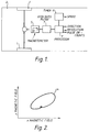
- a method of detecting direction of rotation, and the number of revolutions of a rotating part which generates a magnetic field locus as it rotates comprising the steps of:
- the present rotation sensor could be part of a navigation system.
- Sample data are shown in table 1, where column RECSUM shows a set of successive sums of the x maximum, y maximum, x minimum and y minimum values by way of an example.
- Column D1 shows the difference between adjacent values in column RECSUM
- column D2 shows the difference between alternate values in column RECSUM
- column D3 shows the difference between every third value in column RECSUM. Even in the presence of noise the value in column D2 is reliably smaller than that in columns D1 and D3, showing that one subsidiary magnetic loop is present.
- the output magnetometer data to be used should therefore be selected as alternate values of, for instance, x maximum and its corresponding y value.
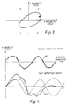
- noise immunity can be gained by using an output point which is not actually on the magnetic locus, but which is reliably related to it.
- An example of such a point is the point x maximum, y maximum, other such points being x maximum, y minimum; x minimum, y maximum and x minimum, y minimum.
- accuracy and sensitivity of the present rotation sensor may under some conditions be improved by combining magnetic field values detected in different orthogonal axes i.e. x+y, x-y etc.
- the processor 9 may be set up to select the most useful combinations of x-y magnetic field values for improved sensor accuracy during calibration of the sensor or an associated magnetic compass.
- a speed or rotation sensor for one or two rotating wheels has been made in a non-contacting sensor which can be fitted at a distance from the rotating part in question.
- the sensor used is a standard magnetometer having one, two or three sensing axes.
- the sensor can be used at the same time to determine vehicle heading if required, and one or two rotation rates. For dead reckoning vehicle location or navigation systems this simplifies the system configuration enormous, since the magnetometers are required in any case for heading sensing.
- An additional feature is that a measure of rejection of unwanted rotation signals can be achieved. This is particularly useful, for instance, in sensing the rotation rates of the two rear wheels of a car. Suitable positioning will allow the sensors to reject the unwanted rotations of the propellor shaft and differential, and measure the rotation of the two rear road wheels.
Landscapes
- Physics & Mathematics (AREA)
- General Physics & Mathematics (AREA)
- Transmission And Conversion Of Sensor Element Output (AREA)
- Rotational Drive Of Disk (AREA)
- Navigation (AREA)
- Supercharger (AREA)
- Measuring Magnetic Variables (AREA)
- Ultra Sonic Daignosis Equipment (AREA)
Claims (3)
- Verfahren zur Erfassung der Drehrichtung und der Anzahl Umdrehungen eines Rotationsteiles (1), weiches während seiner Umdrehung ein zentriertes Magnetfeld erzeugt, gekennzeichnet durch folgende Schritte:(i) Einrichten eines Sensors zur Erfassung des Magnetfeldes in zwei zum Rotationsteil benachbarten orthogonalen Achsen (X,Y),(ii) Umwandlung eines das Magnetfeld anzeigenden Ausgangssignales, welches von jeder Achse erzeugt worden ist, in ein digitales Signal, und Zuführen des digitalen Signales in einen Prozessor,(iii) Betreiben des Prozessors derart, dass das Maximum und Minimum der X- und Y- Magnetfeldwerte in Echtzeit abgefragt werden und eine Sequenz von vier Maximal- und Minimalwerten aufgenommen werden,(iv) Ermittlung, welche der beiden Sequenzen X-Maximum, Y-Maximum, X-Minimum, Y-Minimum oder X-Maximum, Y-Minimum, X-Minimum, Y-Maximum stattfindet,(v) Erzeugung eines Einzelwertes, welcher einen Maximal- oder Minimalwert oder eine kombinierte Summe der Maximal- und Minimalwerte jeder aufgenommenen Sequenz darstellt,(vi) Berechnung für jeden Einzelwert der Aenderung zwischen dem jetzigen Wert und dem letzten Wert, dem jetzigen Wert und dem vorletzten Wert, dem jetzigen Wert und dem drittletzten Wert und Speicherung der Ergebnisse als drei erste Differenzsätze (D1,D2,D3),(ii) Berechnung für jeden Wert in den ersten Differenzsätzen der Differenz zwischen sich und dem vorgehenden Wert des selben Satzes und Speicherung der Resultate als drei zweite Differenzsätze (DD1, DD2, DD3),(viii) Berechnung für jeden Wert des zweiten Differenzsatzes der Differenz zwischen sich und dem vorhergehenden Wert des selben Satzes und Speicherung der Resultate als drei dritte Differenzsätze (DDD1, DDD2, DDD3),(ix) Bestimmung, welcher der vorgängig erwähnten dritten Differenzsätze Werte aufweist, welche im Vergleich näher bei Null liegen, dadurch die Anzahl der subsidiaren Magnetfelder am Ort bestimmend und Ezeugung eines Ausgangssignals, welches jedesmal, wenn eine Anzahl von Sequenzen von Maximal- und Minimalwerten, bestimmt durch die Anzahl von subsidiaren Feldern, erkannt worden sind, eine vollständig abgeschlossene Umdrehung anzeigt.
- Verfahren nach Anspruch 1, dadurch gekennzeichnet, dass nachfolgend an Schritt (viii) höhere Differenzsätze bestimmt werden.
- Verfahren nach Anspruch 1 oder 2, bei welchem in Schritt (iii) für jeden X-Maximal- und X-Minimalwert der zugehörige Y-Wert aufgenommen wird und für jeden Y-Maximal- und Y-Minimalwert der zugehörige X-Wert aufgenommen wird und in Schritt (v) die zugehörigen Y- und X-Werte ebenfalls zur Erzeugung des Einzelwertes verwendet werden können.
Priority Applications (1)
| Application Number | Priority Date | Filing Date | Title |
|---|---|---|---|
| AT89307604T ATE100211T1 (de) | 1988-07-29 | 1989-07-25 | Drehungssensor. |
Applications Claiming Priority (2)
| Application Number | Priority Date | Filing Date | Title |
|---|---|---|---|
| GB888818136A GB8818136D0 (en) | 1988-07-29 | 1988-07-29 | Rotation sensor |
| GB8818136 | 1988-07-29 |
Publications (3)
| Publication Number | Publication Date |
|---|---|
| EP0358320A2 EP0358320A2 (de) | 1990-03-14 |
| EP0358320A3 EP0358320A3 (de) | 1991-04-03 |
| EP0358320B1 true EP0358320B1 (de) | 1994-01-12 |
Family
ID=10641345
Family Applications (1)
| Application Number | Title | Priority Date | Filing Date |
|---|---|---|---|
| EP89307604A Expired - Lifetime EP0358320B1 (de) | 1988-07-29 | 1989-07-25 | Drehungssensor |
Country Status (5)
| Country | Link |
|---|---|
| EP (1) | EP0358320B1 (de) |
| AT (1) | ATE100211T1 (de) |
| DE (1) | DE68912245T2 (de) |
| ES (1) | ES2047676T3 (de) |
| GB (2) | GB8818136D0 (de) |
Cited By (1)
| Publication number | Priority date | Publication date | Assignee | Title |
|---|---|---|---|---|
| US20120310442A1 (en) * | 2009-12-02 | 2012-12-06 | Doutaz Jerome | System and method for assisting the driver of a biomechanically driven vehicle including at least one wheel |
Families Citing this family (3)
| Publication number | Priority date | Publication date | Assignee | Title |
|---|---|---|---|---|
| DE4111171C1 (de) * | 1991-04-06 | 1992-05-27 | Mannesmann Kienzle Gmbh, 7730 Villingen-Schwenningen, De | |
| JP3643463B2 (ja) | 1997-04-30 | 2005-04-27 | パイオニア株式会社 | 車輪の回転数検出装置及び走行距離検出装置 |
| IT1293905B1 (it) | 1997-05-28 | 1999-03-11 | Sgs Thomson Microelectronics | Sensore di posizione bidimensionale di tipo magnetico, in particolare per applicazioni automobilistiche. |
Family Cites Families (5)
| Publication number | Priority date | Publication date | Assignee | Title |
|---|---|---|---|---|
| US3824455A (en) * | 1971-12-06 | 1974-07-16 | Raytheon Co | Apparatus for generating mutually orthogonal sinusoidal signals utilizing orthogonal hall plates which are relatively adjustable |
| JPS54148578A (en) * | 1978-04-18 | 1979-11-20 | Nec Corp | Rotating direction detector |
| US4262427A (en) * | 1979-08-10 | 1981-04-21 | Sperry Corporation | Flux valve compass system |
| FI77932C (fi) * | 1984-12-19 | 1989-05-10 | Hannu Purhonen | Fjaerrkompass. |
| DE3639208A1 (de) * | 1986-11-15 | 1988-05-19 | Bosch Gmbh Robert | Magnetoresistiver sensor zur abgabe von elektrischen signalen |
-
1988
- 1988-07-29 GB GB888818136A patent/GB8818136D0/en active Pending
- 1988-11-07 GB GB8826003A patent/GB2221307B/en not_active Expired - Lifetime
-
1989
- 1989-07-25 ES ES89307604T patent/ES2047676T3/es not_active Expired - Lifetime
- 1989-07-25 DE DE89307604T patent/DE68912245T2/de not_active Expired - Fee Related
- 1989-07-25 AT AT89307604T patent/ATE100211T1/de not_active IP Right Cessation
- 1989-07-25 EP EP89307604A patent/EP0358320B1/de not_active Expired - Lifetime
Cited By (2)
| Publication number | Priority date | Publication date | Assignee | Title |
|---|---|---|---|---|
| US20120310442A1 (en) * | 2009-12-02 | 2012-12-06 | Doutaz Jerome | System and method for assisting the driver of a biomechanically driven vehicle including at least one wheel |
| US9267800B2 (en) * | 2009-12-02 | 2016-02-23 | Movea | System and method for assisting the driver of a biomechanically driven vehicle including at least one wheel |
Also Published As
| Publication number | Publication date |
|---|---|
| EP0358320A3 (de) | 1991-04-03 |
| GB8826003D0 (en) | 1988-12-14 |
| ATE100211T1 (de) | 1994-01-15 |
| GB2221307A (en) | 1990-01-31 |
| GB8818136D0 (en) | 1988-09-01 |
| GB2221307B (en) | 1992-04-08 |
| EP0358320A2 (de) | 1990-03-14 |
| ES2047676T3 (es) | 1994-03-01 |
| DE68912245D1 (de) | 1994-02-24 |
| DE68912245T2 (de) | 1994-05-05 |
Similar Documents
| Publication | Publication Date | Title |
|---|---|---|
| US4732494A (en) | Bearing or roller bearing with data sensor | |
| US9080896B2 (en) | Method for analyzing signals from an angle sensor | |
| US6498474B1 (en) | Rotational velocity and direction sensing system | |
| CN108072318B (zh) | 测量绝对角位置 | |
| US8664943B2 (en) | Position detecting apparatus | |
| EP2999943B1 (de) | System und verfahren zur bereitstellung einer für einen signaturbereich in einem ziel und eine drehrichtung repräsentativen signalcodierung | |
| US6762897B1 (en) | Magnetic encoder apparatus | |
| US6229299B1 (en) | System and method for computing the angular velocity and direction of a rotational body | |
| EP2965093B1 (de) | Geschwindigkeitssensor | |
| US11215681B2 (en) | Magnetic field sensor with stray field immunity and large air gap performance | |
| EP3469314B1 (de) | Magnetfeldsensor zur erfassung einer nähe und/oder eines standorts eines objekts | |
| US20150091554A1 (en) | Magnetic encoder for producing an index signal | |
| US6515471B1 (en) | Absolute position hall string sensor | |
| EP0358320B1 (de) | Drehungssensor | |
| EP1371937A1 (de) | Drehwinkeldetektor und einrichtung mit dem detektor | |
| CN1040153C (zh) | 变速器输出轴转速传感器 | |
| CN101876559B (zh) | 位置检测装置及其信号处理装置和方法 | |
| US11512980B2 (en) | Absolute position detection device and detection method of rotating body | |
| US20170276695A1 (en) | Sensor-bearing unit, mechanical system comprising such unit and method for manufacturing such unit | |
| EP3255391A1 (de) | Aufzeichnungsgerät für magnetischen automatisierungsdurchfluss | |
| US7973528B2 (en) | Sensor device | |
| US20250341435A1 (en) | Magnetic-based torque sensor | |
| CN224083375U (zh) | 一种基于霍尔传感器的电机角度检测装置 | |
| US20220018685A1 (en) | Absolute position detection device and detection method of rotating body using magnetic material | |
| CN219608061U (zh) | 一种感应式磁编码器 |
Legal Events
| Date | Code | Title | Description |
|---|---|---|---|
| PUAI | Public reference made under article 153(3) epc to a published international application that has entered the european phase |
Free format text: ORIGINAL CODE: 0009012 |
|
| AK | Designated contracting states |
Kind code of ref document: A2 Designated state(s): AT BE CH DE ES FR GR IT LI LU NL SE |
|
| PUAL | Search report despatched |
Free format text: ORIGINAL CODE: 0009013 |
|
| RAP1 | Party data changed (applicant data changed or rights of an application transferred) |
Owner name: ROKE MANOR RESEARCH LIMITED |
|
| AK | Designated contracting states |
Kind code of ref document: A3 Designated state(s): AT BE CH DE ES FR GR IT LI LU NL SE |
|
| 17P | Request for examination filed |
Effective date: 19910424 |
|
| 17Q | First examination report despatched |
Effective date: 19920305 |
|
| GRAA | (expected) grant |
Free format text: ORIGINAL CODE: 0009210 |
|
| AK | Designated contracting states |
Kind code of ref document: B1 Designated state(s): AT BE CH DE ES FR GR IT LI LU NL SE |
|
| REF | Corresponds to: |
Ref document number: 100211 Country of ref document: AT Date of ref document: 19940115 Kind code of ref document: T |
|
| ET | Fr: translation filed | ||
| REF | Corresponds to: |
Ref document number: 68912245 Country of ref document: DE Date of ref document: 19940224 |
|
| REG | Reference to a national code |
Ref country code: ES Ref legal event code: FG2A Ref document number: 2047676 Country of ref document: ES Kind code of ref document: T3 |
|
| ITF | It: translation for a ep patent filed | ||
| REG | Reference to a national code |
Ref country code: GR Ref legal event code: FG4A Free format text: 3011239 |
|
| PLBE | No opposition filed within time limit |
Free format text: ORIGINAL CODE: 0009261 |
|
| STAA | Information on the status of an ep patent application or granted ep patent |
Free format text: STATUS: NO OPPOSITION FILED WITHIN TIME LIMIT |
|
| 26N | No opposition filed | ||
| EAL | Se: european patent in force in sweden |
Ref document number: 89307604.2 |
|
| PGFP | Annual fee paid to national office [announced via postgrant information from national office to epo] |
Ref country code: LU Payment date: 19960701 Year of fee payment: 8 |
|
| PGFP | Annual fee paid to national office [announced via postgrant information from national office to epo] |
Ref country code: FR Payment date: 19960709 Year of fee payment: 8 |
|
| PGFP | Annual fee paid to national office [announced via postgrant information from national office to epo] |
Ref country code: AT Payment date: 19960711 Year of fee payment: 8 |
|
| PGFP | Annual fee paid to national office [announced via postgrant information from national office to epo] |
Ref country code: SE Payment date: 19960717 Year of fee payment: 8 |
|
| PGFP | Annual fee paid to national office [announced via postgrant information from national office to epo] |
Ref country code: NL Payment date: 19960729 Year of fee payment: 8 Ref country code: ES Payment date: 19960729 Year of fee payment: 8 |
|
| PGFP | Annual fee paid to national office [announced via postgrant information from national office to epo] |
Ref country code: GR Payment date: 19960731 Year of fee payment: 8 |
|
| PGFP | Annual fee paid to national office [announced via postgrant information from national office to epo] |
Ref country code: DE Payment date: 19960802 Year of fee payment: 8 |
|
| PGFP | Annual fee paid to national office [announced via postgrant information from national office to epo] |
Ref country code: CH Payment date: 19960805 Year of fee payment: 8 |
|
| PGFP | Annual fee paid to national office [announced via postgrant information from national office to epo] |
Ref country code: BE Payment date: 19960911 Year of fee payment: 8 |
|
| PG25 | Lapsed in a contracting state [announced via postgrant information from national office to epo] |
Ref country code: LU Free format text: LAPSE BECAUSE OF NON-PAYMENT OF DUE FEES Effective date: 19970725 Ref country code: AT Free format text: LAPSE BECAUSE OF NON-PAYMENT OF DUE FEES Effective date: 19970725 |
|
| PG25 | Lapsed in a contracting state [announced via postgrant information from national office to epo] |
Ref country code: SE Effective date: 19970726 Ref country code: ES Free format text: LAPSE BECAUSE OF THE APPLICANT RENOUNCES Effective date: 19970726 |
|
| PG25 | Lapsed in a contracting state [announced via postgrant information from national office to epo] |
Ref country code: LI Free format text: LAPSE BECAUSE OF NON-PAYMENT OF DUE FEES Effective date: 19970731 Ref country code: GR Free format text: LAPSE BECAUSE OF NON-PAYMENT OF DUE FEES Effective date: 19970731 Ref country code: CH Free format text: LAPSE BECAUSE OF NON-PAYMENT OF DUE FEES Effective date: 19970731 Ref country code: BE Free format text: LAPSE BECAUSE OF NON-PAYMENT OF DUE FEES Effective date: 19970731 |
|
| BERE | Be: lapsed |
Owner name: ROKE MANOR RESEARCH LTD Effective date: 19970731 |
|
| PG25 | Lapsed in a contracting state [announced via postgrant information from national office to epo] |
Ref country code: NL Free format text: LAPSE BECAUSE OF NON-PAYMENT OF DUE FEES Effective date: 19980201 |
|
| REG | Reference to a national code |
Ref country code: CH Ref legal event code: PL |
|
| PG25 | Lapsed in a contracting state [announced via postgrant information from national office to epo] |
Ref country code: FR Free format text: LAPSE BECAUSE OF NON-PAYMENT OF DUE FEES Effective date: 19980331 |
|
| NLV4 | Nl: lapsed or anulled due to non-payment of the annual fee |
Effective date: 19980201 |
|
| PG25 | Lapsed in a contracting state [announced via postgrant information from national office to epo] |
Ref country code: DE Free format text: LAPSE BECAUSE OF NON-PAYMENT OF DUE FEES Effective date: 19980401 |
|
| EUG | Se: european patent has lapsed |
Ref document number: 89307604.2 |
|
| REG | Reference to a national code |
Ref country code: FR Ref legal event code: ST |
|
| REG | Reference to a national code |
Ref country code: ES Ref legal event code: FD2A Effective date: 20001009 |
|
| PG25 | Lapsed in a contracting state [announced via postgrant information from national office to epo] |
Ref country code: IT Free format text: LAPSE BECAUSE OF NON-PAYMENT OF DUE FEES;WARNING: LAPSES OF ITALIAN PATENTS WITH EFFECTIVE DATE BEFORE 2007 MAY HAVE OCCURRED AT ANY TIME BEFORE 2007. THE CORRECT EFFECTIVE DATE MAY BE DIFFERENT FROM THE ONE RECORDED. Effective date: 20050725 |