EP0357930A1 - Cold-rolled girder - Google Patents
Cold-rolled girder Download PDFInfo
- Publication number
- EP0357930A1 EP0357930A1 EP89113747A EP89113747A EP0357930A1 EP 0357930 A1 EP0357930 A1 EP 0357930A1 EP 89113747 A EP89113747 A EP 89113747A EP 89113747 A EP89113747 A EP 89113747A EP 0357930 A1 EP0357930 A1 EP 0357930A1
- Authority
- EP
- European Patent Office
- Prior art keywords
- web
- flange
- cold
- lip
- chord
- Prior art date
- Legal status (The legal status is an assumption and is not a legal conclusion. Google has not performed a legal analysis and makes no representation as to the accuracy of the status listed.)
- Granted
Links
Images


Classifications
-
- E—FIXED CONSTRUCTIONS
- E04—BUILDING
- E04C—STRUCTURAL ELEMENTS; BUILDING MATERIALS
- E04C3/00—Structural elongated elements designed for load-supporting
- E04C3/02—Joists; Girders, trusses, or trusslike structures, e.g. prefabricated; Lintels; Transoms; Braces
- E04C3/04—Joists; Girders, trusses, or trusslike structures, e.g. prefabricated; Lintels; Transoms; Braces of metal
- E04C3/06—Joists; Girders, trusses, or trusslike structures, e.g. prefabricated; Lintels; Transoms; Braces of metal with substantially solid, i.e. unapertured, web
- E04C3/07—Joists; Girders, trusses, or trusslike structures, e.g. prefabricated; Lintels; Transoms; Braces of metal with substantially solid, i.e. unapertured, web at least partly of bent or otherwise deformed strip- or sheet-like material
-
- B—PERFORMING OPERATIONS; TRANSPORTING
- B65—CONVEYING; PACKING; STORING; HANDLING THIN OR FILAMENTARY MATERIAL
- B65G—TRANSPORT OR STORAGE DEVICES, e.g. CONVEYORS FOR LOADING OR TIPPING, SHOP CONVEYOR SYSTEMS OR PNEUMATIC TUBE CONVEYORS
- B65G1/00—Storing articles, individually or in orderly arrangement, in warehouses or magazines
- B65G1/02—Storage devices
- B65G1/04—Storage devices mechanical
- B65G1/06—Storage devices mechanical with means for presenting articles for removal at predetermined position or level
- B65G1/065—Storage devices mechanical with means for presenting articles for removal at predetermined position or level with self propelled cars
-
- E—FIXED CONSTRUCTIONS
- E04—BUILDING
- E04C—STRUCTURAL ELEMENTS; BUILDING MATERIALS
- E04C3/00—Structural elongated elements designed for load-supporting
- E04C3/02—Joists; Girders, trusses, or trusslike structures, e.g. prefabricated; Lintels; Transoms; Braces
- E04C3/04—Joists; Girders, trusses, or trusslike structures, e.g. prefabricated; Lintels; Transoms; Braces of metal
- E04C2003/0404—Joists; Girders, trusses, or trusslike structures, e.g. prefabricated; Lintels; Transoms; Braces of metal beams, girders, or joists characterised by cross-sectional aspects
- E04C2003/0408—Joists; Girders, trusses, or trusslike structures, e.g. prefabricated; Lintels; Transoms; Braces of metal beams, girders, or joists characterised by cross-sectional aspects characterised by assembly or the cross-section
- E04C2003/0421—Joists; Girders, trusses, or trusslike structures, e.g. prefabricated; Lintels; Transoms; Braces of metal beams, girders, or joists characterised by cross-sectional aspects characterised by assembly or the cross-section comprising one single unitary part
-
- E—FIXED CONSTRUCTIONS
- E04—BUILDING
- E04C—STRUCTURAL ELEMENTS; BUILDING MATERIALS
- E04C3/00—Structural elongated elements designed for load-supporting
- E04C3/02—Joists; Girders, trusses, or trusslike structures, e.g. prefabricated; Lintels; Transoms; Braces
- E04C3/04—Joists; Girders, trusses, or trusslike structures, e.g. prefabricated; Lintels; Transoms; Braces of metal
- E04C2003/0404—Joists; Girders, trusses, or trusslike structures, e.g. prefabricated; Lintels; Transoms; Braces of metal beams, girders, or joists characterised by cross-sectional aspects
- E04C2003/0426—Joists; Girders, trusses, or trusslike structures, e.g. prefabricated; Lintels; Transoms; Braces of metal beams, girders, or joists characterised by cross-sectional aspects characterised by material distribution in cross section
- E04C2003/0434—Joists; Girders, trusses, or trusslike structures, e.g. prefabricated; Lintels; Transoms; Braces of metal beams, girders, or joists characterised by cross-sectional aspects characterised by material distribution in cross section the open cross-section free of enclosed cavities
Definitions
- the invention relates to a cold profile carrier with a lower flange pointing to one side, an upper flange pointing to the other side and an obtuse-angled web connecting with a lower flange and upper flange as well as with a lip on the upper flange and with a lip on the lower flange.
- Such cold profile girders are known in various embodiments, among other things as purlins for an inclined roof skin from DE-OS 33 15 694.
- the lower flange and the upper flange lie in mutually parallel planes and are bent over an oblique one in the region of the belts Bridge connected to each other and each have a lip on the free edge.
- the well-known purlin is designed as a Z-profile.
- the object of the invention is to provide a cold section beam, the profile of which - viewed in cross section - is particularly suitable for accommodating a load that deviates from the vertical under favorable tension conditions in the cold section beam and to design it in such a way that it can accommodate both smaller and larger bearing loads with economical material expenditure can
- Another object of the invention is to provide the cold profile carrier for an advantageous use.
- the web is bent in its central region towards the side on which the lower chord lies, and in this kink of the web the vertical lower part of the web adjacent to the lower chord with the largely straight upper part of the web blunts Forms an angle, that the adjoining the upper part of the web is obliquely rising with respect to a horizontal plane and in its connection area to the upper part of the web to this horizontal plane is at an acute angle of 5 ° to 50 °, that the upper band is wider than the lower flange and that the upper flange is at least returned to this vertical reference plane with respect to a vertical reference plane determined by the vertical lower part of the web.
- the chosen marking of the invention is recognizable for the person skilled in the art from the regular installation state of the cold profile girder according to the invention, in which the lower part of the web adjoining the lower flange is perpendicular to the horizontal, the lower flange itself not running completely horizontally in special cases, but according to claim 2 the lower flange can form an angle ⁇ between 80 ° and 100 °.
- the profile design according to claim 3 is preferred, in which the lower part of the web and the lower flange form a right angle.
- the cold-profile support with the lower flange as a foot can stand on a flat surface.
- the lower lip can be a side stop for a cold-profile beam seated on a longitudinal beam with the lower flange.
- the profile design is expedient, which provides that the upper lip of the upper flange and the lower lip of the lower flange point in the same direction and are parallel to the vertical lower part of the web.
- a preferred embodiment of the invention provides that the upper chord is slightly curved. It not only has a special buckling stiffness, but also does justice to the extreme load alternatives of a smaller load in the area of the connection to the upper part of the web as well as a larger load that attacks more on the free end of the upper flange.
- the lower chord lies within a projection of the upper chord parallel to the vertical lower part of the web in the horizontal plane passing through the shoulder of the lower chord, which is determined by the lower chord itself in the case of a lower chord set at right angles .
- the cold profile beam with a lip on the top flange can be easily reinforced and make a closed profile carrier by connecting the lower part of the web and the upper lip to one another via a laterally attached, flat connecting element.
- an inventive use of the cold profile beam is proposed, namely the use of a cold profile beam with the features according to one of claims 1 to 9 as a support element for cylindrical bodies, it being provided that two cold profile beams are arranged in mirror image, spaced apart and parallel to each other and the one another away rising top chords are supports for the cylindrical body.
- the two cold profile girders are supported on fixed abutments at least in the area of their girder ends.
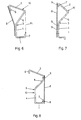
- the basic shape of the profile shown in Fig. 1 shows a cold profile beam with a straight lower flange 1, a straight upper flange 2 and a lower flange 1 and upper flange 2 connecting bent web 3, in which the straight vertical lower part 4 of the web 3 at a right angle ⁇ adjoins the lower flange 1 and in the central region towards the side on which the lower flange 1 is bent and forms an obtuse angle ⁇ with the straight upper part 5 of the web 3.
- the angle ⁇ will usually be 110 ° to 150 °.
- the upper chord 2 adjoining the upper part 5 of the web 3 is directed in the opposite direction to the lower chord 1 and is designed to rise obliquely.
- An upper lip 6 is provided on the upper chord 2 and a lower lip 7 on the lower chord 1, which points in the same direction, here downward.
- the lower flange 1 which is attached to the lower part 4 of the web 3 at a right angle ⁇ , determines a plane E1 which is regularly horizontal in the installed state of the cold profile girder, parallel to which an imaginary horizontal plane E2 which is caused by the transition between the upper part 5 of the web 3 and top flange 2 goes, is shown. Furthermore, a vertical reference plane E3 is drawn through the transition from the lower flange 1 to the lower part 4 of the web 3. The vertical lower part 4 of the web 3 lies in this vertical reference plane E3.
- the upper chord 2 forms in its connection area and, since the upper chord 2 is flat, an overall acute angle ⁇ , which should be between 5 ° and 50 °, is approximately 30 ° here.
- Fig. 1 also shows that the upper flange 2 is returned from its connection to the upper part 5 of the web 3 beyond the vertical reference plane E3.
- An arrow A is intended to indicate a direction of a load that deviates from the vertical.
- Fig. 2 the top chord 2 is slightly curved, the beginning and end of the curvature should be expressed by the tangent t and the tangent t1.
- the tangents t and t1 are an expression of the slope of the upper chord and form the angle ⁇ assigned to the connection area of the upper chord 2 and a smaller angle ⁇ 1 with the horizontal plane E2.
- the two angles mentioned here are approximately 35 ° and 15 °.
- Fig. 3 shows a cold profile beam, in which the upper lip 6 and the vertical lower part 4 of the web 3 are in the vertical reference plane E3.
- the short transition piece 4 has a short transition piece parallel to the lower part 4 of the web 3 as part of the upper part 5 of the web 3.
- the short transition piece merely dissolves the transition between the upper part 5 of the web 3 and the upper flange 2 in two transitions that are easier to manufacture in the case of thick sheets, without leaving the relatively simple basic shape of the cold profile girder in principle.
- the upper lip 6 of the upper flange 2 points slightly outwards and the lower lip 7 of the lower flange 1 is directed upwards.
- Each of the profile shapes of the cold profile support shown is accessible for production by folding a sheet metal strip of appropriate length, or by continuous roll forming of a sheet metal strip.
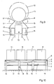
- a flat connecting element 8 is attached here in the form of a plastic plate, which is connected to the upper lip 6 and the lower part 4 of the web 3 is glued.
- the attached flat connecting element 8 is a steel plate which is connected to the cold-profile support 10 by spot welds 9.
- FIG. 8 shows the formation of a closed profile carrier, in that the steel plate is welded onto the cold profile carrier 10 according to FIG. 4 on the upper part 4 of the web and on the lower lip 6.
- two cold profile beams 10 can be seen in a schematic representation, which are arranged in mirror image, at a distance and parallel to each other.
- the upper chords 2 rising away from each other are support for a cylindrical body 11.
- a further cylindrical body 12 is drawn in by a dash-dotted line in order to illustrate that an example is given here that the smaller load resulting from the cylindrical body 11 closer to the transition between the upper part 5 of the web 3 and the upper flange 2 can attack while the resulting load from the larger cylindrical body 12 will attack further away.
- FIG. 9 additionally shows a transport carriage 13, the wheels 14 of which find their lane on the lower flange 1 and which is equipped with a lifting device 15.
- a cylindrical body 11 for example a paper bale
- the cold-profile girders 10 perform two functions in the arrangement according to FIG. 9, namely the absorption of a stationary load via the upper straps 2 and the absorption of a transport load via the lower straps 1.
- Fig. 10 shows the side view of a section from a shelf warehouse, possibly a high-bay warehouse, in which fixed abutments 16 are now shown in addition to the basic elements shown in Fig. 9, which end below the upper lip 6 of the cold profile beam in this embodiment.
- the cylindrical body 11 is resiliently received, so that hard impact loads are avoided when the body 11 is placed on.
- such measures prove to be advantageous because they also do not allow vibrations from the travel movements of the vehicles 13 to penetrate the paper bales.
- an elastic abutment 18 In addition to the fixed abutments 16, which rest on a support 17, an elastic abutment 18, a frame connecting the two cold-profile supports, is provided, which can be supported on a bearing block 19 in a horizontally sliding manner.
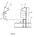
- FIG. 11 shows a view from below of a support structure in a high-bay warehouse with U-profile elements 20, on which the lower flange 1 of the profile carrier 10 rests and to which the lower lip 7 is fastened.
- the lower part 4 of the web and the upper lip 6 are screwed onto the support element 16. 3 has proven particularly useful for this.
- the cold profile girder 10 is used to transfer loads, which are designated R, P1 and P2.
- the cold profile girders 10 provided for the transfer of the loads, shown here to scale, are arranged at a distance a from one another.
- the load R results from a transport carriage 13 which moves in the longitudinal direction on the lower chords 1 of the two cold-profile girders 10.
- the loads P1 and P2 result from storage material (for example paper bales) which are transported on the transport carriage 13 with the lifting device 15 and act on the upper chord 2 of the cold profile carrier 10 in the lowered state.
- storage material for example paper bales
- the cold profile support 10 can transmit the load R as well as the loads P1 and P2 without any noteworthy twisting of the cross section.
- the center of thrust M is such that there are small lever arms d.
- the direction of rotation of the resulting torsional moments is also directed so that jamming of the load between the two cold profile beams is prevented.
- the line of action of the loads also advantageously shifts such that the lever arm d is reduced.
- Another advantage of the special shape of the cold-profile girder 10 can be seen in the position of the shear center M relative to the center of gravity S. Both points are close to one another. As a result of this and due to the position of the main stress levels of the profile shape, there are overall balanced stress relationships in all points of the cross section.
- the scale representations of the cold profile beam 10 in FIG. 10 show that with this optimized shape the width b1 of the lower flange 1 corresponds to the dimension b2 of the projection of the upper flange 2 (see also FIG. 1) and is approximately in a ratio of 1: 1.75 and that the cross-sectional lengths from the upper part 5 to the lower part 4 of the web 3 behave approximately as 1: 1.25.
- the obtuse angle ⁇ between the lower part 1 and the upper part 2 of the web 3 is 115 °; the angles and 1 at the approach and end of the top chord 2 to the horizontal are 30 ° and 20 °.
- a common construction type according to FIG. 3 of a cold-profile girder made of 4.5 mm thick steel sheet, including a 50 mm long lower lip, has a construction height of approx. 520 mm and a construction width of approx. 180 mm.
- the bending radius in the transitions between the lower lip 6 and the lower flange 1 and between the lower flange 1 and the vertical lower part 4 of the web 3 is relatively small at around 1.6 to 1.8 times the sheet thickness, and the bending radius in the bend between the lower part 4 and the upper part 5 of the web 3 and between the upper part 4 of the web 3 and the upper flange corresponds approximately to 2 to 3 times the sheet thickness and the upper lip 6 is set with a bending radius of 2.5 to 4 times the sheet thickness.
- the upper part 5 of the web 3 is approximately 1: 1.2 in length to the lower part 4
- the upper part 5 of the web 3 and the upper flange 1 are approximately of the same length.
Abstract
Description
Die Erfindung betrifft einen Kaltprofilträger mit einem zu einer Seite weisenden Untergurt, einem zur anderen Seite weisenden Obergurt und mit einem Untergurt und Obergurt miteinander verbindenden stumpfwinklig geknickten Steg sowie mit einer Lippe am Ober- und mit einer Lippe am Untergurt. Derartige Kaltprofilträger sind in verschiedenen Ausführungsformen bekannt, unter anderem als Pfette für eine geneigt verlaufende Dachhaut aus der DE-OS 33 15 694. Bei diesem bekannten Pfettenprofil liegen Untergurt und Obergurt in zueinander parallelen Ebenen, sind über einen schrägen, im Bereich der Gurte jeweils geknickten Steg miteinander verbunden und haben jeweils eine Lippe an der freien Kante. Die bekannte Pfette ist als Z-Profil gestaltet.The invention relates to a cold profile carrier with a lower flange pointing to one side, an upper flange pointing to the other side and an obtuse-angled web connecting with a lower flange and upper flange as well as with a lip on the upper flange and with a lip on the lower flange. Such cold profile girders are known in various embodiments, among other things as purlins for an inclined roof skin from DE-OS 33 15 694. In this known purlin profile, the lower flange and the upper flange lie in mutually parallel planes and are bent over an oblique one in the region of the belts Bridge connected to each other and each have a lip on the free edge. The well-known purlin is designed as a Z-profile.
Aufgabe der Erfindung ist es, einen Kaltprofilträger zu schaffen, dessen Profil - im Querschnitt betrachtet - besonders geeignet ist, eine von der Senkrechten abweichenden Auflast bei günstigen Spannungsverhältnissen im Kaltprofilträger aufzunehmen und so auszugestalten, daß es mit wirtschaftlichem Materialaufwand sowohl kleinere wie auch größere Auflagelasten aufzunehmen vermag. Eine weitere Aufgabe der Erfindung ist es, den Kaltprofilträger einem vorteilhaften Verwendungszweck zuzuführen.The object of the invention is to provide a cold section beam, the profile of which - viewed in cross section - is particularly suitable for accommodating a load that deviates from the vertical under favorable tension conditions in the cold section beam and to design it in such a way that it can accommodate both smaller and larger bearing loads with economical material expenditure can Another object of the invention is to provide the cold profile carrier for an advantageous use.
Erfindungsgemäß wird daher vorgeschlagen, daß der Steg in seinem Mittelbereich zu der Seite hin, auf der der Untergurt liegt, geknickt ist und in diesem Knick des Steges der dem Untergurt benachbarte gerade vertikale untere Teil des Steges mit dem weitgehend geraden oberen Teil des Steges den stumpfen Winkel bildet, daß der an den oberen Teil des Steges anschließende Obergurt gegenüber einer horizontalen Ebene schräg ansteigend ausgebildet ist und in seinem Anschlußbereich an den oberen Teil des Steges zu dieser horizontalen Ebene in einem spitzen Winkel von 5° bis 50° steht, daß der Obergurt breiter ist als der Untergurt und daß der Obergurt in Bezug auf einedurch den vertikalen unteren Teil des Steges bestimmte vertikale Bezugsebene mindestens bis zu dieser vertikalen Bezugsebene zurückgeführt ist.According to the invention it is therefore proposed that the web is bent in its central region towards the side on which the lower chord lies, and in this kink of the web the vertical lower part of the web adjacent to the lower chord with the largely straight upper part of the web blunts Forms an angle, that the adjoining the upper part of the web is obliquely rising with respect to a horizontal plane and in its connection area to the upper part of the web to this horizontal plane is at an acute angle of 5 ° to 50 °, that the upper band is wider than the lower flange and that the upper flange is at least returned to this vertical reference plane with respect to a vertical reference plane determined by the vertical lower part of the web.
Die gewählte Kennzeichnung der Erfindung geht für den Fachmann erkennbar vom regelmäßigen Einbauzustand des erfindungsgemäßen Kaltprofilträgers aus, bei dem der an den Untergurt anschließende untere Teil des Steges senkrecht zur Horizontalen steht, wobei der Untergurt selbst in Sonderfällen nicht ganz horizontal verläuft, sondern gemäß Anspruch 2 mit dem Untergurt einen Winkel α zwischen 80° und 100° bilden kann.
Bevorzugt wird jedoch die Profilgestaltung nach Anspruch 3, bei der der untere Teil des Steges und der Untergurt einen rechten Winkel bilden. Ist bei dieser Ausführungsform die untere Lippe am Untergurt nach oben gerichtet, so kann der Kaltprofilträger mit dem Untergurt als Fuß auf einer ebenen Unterlage stehen. Ist die untere Lippe nach unten gerichtet, so kann sie seitlicher Anschlag für einen auf einem Längsträger mit dem Untergurt aufsitzenden Kaltprofilträger sein.
Zweckmäßig ist für viele Anwendungsfälle die Profilgestaltung nach Anspruch 4, die vorsieht, daß die obere Lippe des Obergurtes und die untere Lippe des Untergurtes in die gleiche Richtung zeigen und parallel zum vertikalen unteren Teil des Steges stehen.The chosen marking of the invention is recognizable for the person skilled in the art from the regular installation state of the cold profile girder according to the invention, in which the lower part of the web adjoining the lower flange is perpendicular to the horizontal, the lower flange itself not running completely horizontally in special cases, but according to claim 2 the lower flange can form an angle α between 80 ° and 100 °.
However, the profile design according to
For many applications, the profile design is expedient, which provides that the upper lip of the upper flange and the lower lip of the lower flange point in the same direction and are parallel to the vertical lower part of the web.
Die Ausführungsform nach Patentanspruch 5, bei der der untere Teil des Steges und die obere Lippe in der durch den unteren Teil des Steges bestimmten senkrechten Bezugsebene liegen, ist insofern montagefreundlich, als sowohl der untere Teil des Steges wie auch die Lippe mit einer senkrechten Fläche eines seitlichen Widerlagers verbunden oder an dieser abgestützt werden können.The embodiment according to
Eine bevorzugte Ausführungsform der Erfindung sieht vor, daß der Obergurt leicht gekrümmt ist. Er weist damit nicht nur eine besondere Beulsteifigkeit auf, sondern wird auch den extremen Belastungsalternativen einer kleineren Auflast im Bereich des Anschlusses zum Oberteil des Steges wie auch einer größeren, mehr zum freien Ende des Obergurtes angreifenden Auflast gerecht.A preferred embodiment of the invention provides that the upper chord is slightly curved. It not only has a special buckling stiffness, but also does justice to the extreme load alternatives of a smaller load in the area of the connection to the upper part of the web as well as a larger load that attacks more on the free end of the upper flange.
In Patentanspruch 7 sind vorteilhafte Dimensionierungen eines Kaltprofilträgers mit gekrümmtem Obergurt niedergelegt. Dabei ist vorgesehen, daß die im Anschlußereich des Obergurtes durch den Winkel γ bestimmte Steigung des Obergurtes im Bereich seiner freien Seite bzw. im Bereich des Überganges zur oberen Lippe einen Winkel γ1 von 5° bis 30° mit einer dem Untergurt parallelen Ebene bildet.In
Zur weiteren Optimierung der Profilgestaltung ist gemäß Anspruch 8 vorgesehen, daß der Untergurt innerhalb einer zum vertikalen unteren Teil des Steges parallelen Projektion des Obergurtes in die durch den Ansatz des Untergurtes gehende horizontale Ebene liegt, die bei einem rechtwinklig angesetzten Untergurt durch den Untergurt selbst bestimmt wird.To further optimize the profile design, it is provided according to
Der Kaltprofilträger mit einer Lippe am Obergurt läßt sich auf einfache Weise verstärken und zu einem geschlossenen Profilträ ger machen, indem gemäß Patentanspruch 9 der untere Teil des Steges und die obere Lippe über ein seitlich angesetztes, flächiges Verbindungselement miteinander verbunden werden.The cold profile beam with a lip on the top flange can be easily reinforced and make a closed profile carrier by connecting the lower part of the web and the upper lip to one another via a laterally attached, flat connecting element.
Nach Patentanspruch 10 wird eine erfindungsgemäße Verwendung des Kaltprofilträgers vorgeschlagen, nämlich die Verwendung eines Kaltprofilträgers mit den Merkmalen nach einem der Ansprüche 1 bis 9 als Stützelement für zylindrische Körper, wobei vorgesehen ist, daß zwei Kaltprofilträger spiegelbildlich, mit Abstand und parallel zueinander angeordnet und die voneinander weg ansteigenden Obergurte Auflagen für die zylindrischen Körper sind. Dabei werden die beiden Kaltprofilträger mindestens im Bereich ihrer Trägerenden auf festen Widerlagern gelagert.According to
Im nachfolgenden wird die Erfindung anhand von Ausführungsbeispielen beschrieben:
Es zeigt, im wesentlichen jeweils als Stirnansicht des Profilträgers
- Fig. 1 die Grundform des Kaltprofilträgers
- Fig. 2 einen Kaltprofilträger mit gewölbtem Obergurt
- Fig. 3 eine bevorzugte Profilform
- Fig. 4 eine weitere Profilform
- Fig. 5 einen Kaltprofilträger, bei dem die untere Lippe nach oben zeigt
- Fig. 6 einen Kaltprofilträger mit einer seitlich befestigten geknickten Kunststoffplatte
- Fig. 7 einen Kaltprofilträger mit einer seitlich befestigten Stahlplatte
- Fig. 8 einen weiteren Kaltprofilträger mit seitlich befestigter Stahlplatte
- Fig. 9 Kaltprofilträger als Stützelement in einem Regallager für Papierrollen
- Fig. 10 eine Seitenansicht einer Sektion eines Papierrollenlagers
- Fig. 11 eine perspektivische Darstellung einer Stützkonstruktion mit der bevorzugten Profilform gemäß Fig. 3
- Fig. 12 eine ausschnittweise Stirnansicht zu Fig. 11
It shows, essentially as a front view of the profile beam
- Fig. 1 shows the basic shape of the cold profile beam
- Fig. 2 shows a cold profile beam with a curved top chord
- Fig. 3 shows a preferred profile shape
- Fig. 4 shows another profile shape
- Fig. 5 shows a cold profile beam, in which the lower lip points upwards
- Fig. 6 shows a cold profile beam with a laterally attached kinked plastic plate
- Fig. 7 shows a cold profile beam with a laterally attached steel plate
- Fig. 8 shows another cold profile beam with a laterally attached steel plate
- Fig. 9 cold profile support as a support element in a shelf warehouse for paper rolls
- Fig. 10 is a side view of a section of a paper roll store
- 11 is a perspective view of a support structure with the preferred profile shape according to FIG. 3
- 12 is a partial front view of FIG. 11
Die in Fig. 1 dargestellte Grundform des Profils zeigt einen Kaltprofilträger mit einem geraden Untergurt 1, einem geraden Obergurt 2 und einem Untergurt 1 und Obergurt 2 verbindenden geknickten Steg 3, bei dem der gerade vertikale untere Teil 4 des Steges 3 unter einem rechten Winkel α an den Untergurt 1 anschließt und im Mittelbereich zu der Seite hin, auf der der Untergurt 1 liegt abgeknickt ist und im Knick mit dem geraden oberen Teil 5 des Steges 3 einen stumpfen Winkel β bildet. Der Winkel β wird in der Regel 110° bis 150° sein. Der an den oberen Teil 5 des Steges 3 anschließende Obergurt 2 ist dem Untergurt 1 entgegengesetzt gerichtet und schräg ansteigend ausgebildet. Am Obergurt 2 ist eine obere Lippe 6, am Untergurt 1 eine untere Lippe 7 vorgesehen, die in dieselbe Richtung, hier nach unten, zeigen.The basic shape of the profile shown in Fig. 1 shows a cold profile beam with a straight
Es sind weiterhin strichpunktierte Projektionslinien P und P1 eingezeichnet, die die senkrechte Projektion des Obergurtes in die Ebene E1 des Untergurtes und veranschaulichen und zeigen, daß der Untergurt 1 innerhalb dieser Projektion liegt.There are also dash-dotted projection lines P and P1 which illustrate the vertical projection of the upper chord into the plane E1 of the lower chord and show that the
Durch den mit einem rechten Winkel α an den unteren Teil 4 des Steges 3 angesetzten Untergurt 1 wird eine im Einbauzustand des Kaltprofilträgers regelmäßig waagerechte Ebene E1 bestimmt, zu der parallel eine gedachte horizontale Ebene E2, die durch den Übergang zwischen oberen Teil 5 des Steges 3 und Obergurt 2 geht, eingezeichnet ist.
Weiterhin ist eine durch den Übergang vom Untergurt 1 zum unteren Teil 4 des Steges 3 gehende senkrechte Bezugsebene E3 eingezeichnet. In dieser senkrechten Bezugsebene E3 liegt der vertikale untere Teil 4 des Steges 3.The
Furthermore, a vertical reference plane E3 is drawn through the transition from the
Mit der horizontalen Ebene E2 bildet der Obergurt 2 in seinem Anschlußbereich und, da der Obergurt 2 eben ist, insgesamt einen spitzen Winkel γ, der zwischen 5° und 50° sein soll, hier bei etwa 30° liegt.With the horizontal plane E2, the
Fig. 1 weist weiterhin aus, daß der Obergurt 2 von seinem Anschluß an den oberen Teil 5 des Steges 3 über die senkrechte Bezugsebene E3 hinaus zurückgeführt ist.Fig. 1 also shows that the
Ein Pfeil A soll eine von der Senkrechten abweichende Richtung einer Last andeuten.An arrow A is intended to indicate a direction of a load that deviates from the vertical.
In Fig. 2 ist der Obergurt 2 leicht gekrümmt, wobei Anfang und Ende der Krümmung durch die Tangente t und die Tangente t1 ausgedrückt sein sollen. Die Tangenten t und t1 sind Ausdruck der Steigung des Obergurtes und bilden einmal den dem Anschlußbereich des Obergurtes 2 zugeordneten Winkel γ , zum anderen einen kleineren Winkel γ 1 Jeweils mit der horizontalen Ebene E2. Die beiden genannten Winkel sind hier etwa 35° und 15°.In Fig. 2 the
Fig. 3 zeigt einen Kaltprofilträger, bei dem die obere Lippe 6 und der vertikale untere Teil 4 des Steges 3 in der senkrechten Bezugsebene E3 liegen.Fig. 3 shows a cold profile beam, in which the
Der in Fig. 4 dargestellte Kaltprofilträger hat als Teil des oberen Teiles 5 des Steges 3 ein dem unteren Teil 4 des Steges 3 paralleles kurzes Übergangsstück.
Das kurze Übergangsstück löst lediglich den Übergang zwischen dem oberen Teil 5 des Steges 3 und dem Obergurt 2 in zwei, bei dicken Blechen fertigungstechnisch einfacher herzustellende Übergänge auf, ohne damit die relativ einfache Grundform des Kaltprofilträgers prinzipiell zu verlassen.4 has a short transition piece parallel to the
The short transition piece merely dissolves the transition between the
Beim Kaltprofilträger nach Fig. 5 zeigt die obere Lippe 6 des Obergurtes 2 leicht nach außen und die untere Lippe 7 des Untergurtes 1 ist nach oben gerichtet.5, the
Jede der gezeigten Profilformen des Kaltprofilträgers ist einer Fertigung durch Abkanten eines Blechstreifens entsprechender Länge, oder durch kontinuierliches Rollformen eines Blechbandes zugänglich.Each of the profile shapes of the cold profile support shown is accessible for production by folding a sheet metal strip of appropriate length, or by continuous roll forming of a sheet metal strip.
Bei dem in Fig. 6 dargestellten Kaltprofilträger 10 mit einer auf den Übergang zwischen den unteren Teil 4 und den oberen Teil 5 des Steges 3 weisenden oberen Lippe 6 ist ein flächiges Verbindungselement 8 hier in Form einer Kunststoffplatte angesetzt, das mit der oberen Lippe 6 und dem unteren Teil 4 des Steges 3 verklebt ist.In the
In Fig. 7 ist das aufgesetzte flachige Verbindungselement 8 eine Stahlplatte, die durch Punktschweißungen 9 mit dem Kaltprofilträger 10 verbunden ist. Fig. 8 zeigt die Bildung eines geschlossenen Profilträgers, indem hier auf den Kaltprofilträger 10 nach Fig. 4 die Stahlplatte am oberen Teil 4 des Steges und an der unteren Lippe 6 angeschweißt ist.In Fig. 7, the attached flat connecting
In Fig. 9 sind in schematischer Darstellung zwei Kaltprofilträger 10 zu sehen, die spiegelbildlich, mit Abstand und parallel zueinander angeordnet sind. Die voneinander weg ansteigenden Obergurte 2 sind Auflage für einen zylindrischen Körper 11. Es ist ein weiterer zylindrischer Körper 12 durch eine strichpunktierte Linie eingezeichnet um so zu verdeutlichen, daß hier ein Beispiel dafür gegeben ist, daß einmal die aus dem zylindrischen Körper 11 resultierende kleinere Auflast näher am Übergang zwischen oberen Teil 5 des Steges 3 und Obergurt 2 entfernt angreifen kann während die resultierende Auflast aus dem größeren zylindrischen Körper 12 davon weiter entfernt angreifen wird.In Fig. 9, two cold profile beams 10 can be seen in a schematic representation, which are arranged in mirror image, at a distance and parallel to each other. The
An dieser Stelle kann auch auf einen besonderen Vorteil der Erfindung hingewiesen werden, die darin besteht, daß eine klemmende Tendenz zwischen zylindrischem Körper 11 und den Obergurten 2 gänzlich vermieden wird.At this point it can also be pointed out a particular advantage of the invention, which consists in that a jamming tendency between the
Fig. 9 zeigt zusätzlich ein Transportwagen 13, dessen Räder 14 auf dem Untergurt 1 ihre Fahrbahn finden und der mit einer Hubvorrichtung 15 ausgerüstet ist. Durch Ausfahren der Hubvorrichtung 15 kann ein zylindrischer Körper 11, beispielsweise ein Papierballen, aufgenommen und abtransportiert werden.FIG. 9 additionally shows a
So wird erkennbar, daß die Kaltprofilträger 10 in der Anordnung nach Fig. 9 zwei Funktionen erfüllen, nämlich die Aufnahme einer ruhenden Last über die Obergurte 2 wie auch die Aufnahme einer Transportlast über die Untergurte 1.It can thus be seen that the cold-
Fig. 10 zeigt die Seitenansicht einer Sektion aus einem Regallager, gegebenenfalls einem Hochregallager, bei der nun zusätzlich zu den in Fig. 9 dargestellten Grundelementen feste Widerlager 16 eingezeichnet sind, die bei dieser Ausführung unterhalb der oberen Lippe 6 des Kaltprofilträgers enden.Fig. 10 shows the side view of a section from a shelf warehouse, possibly a high-bay warehouse, in which
Bei dieser Gestaltung werden die zylinderischen Körper 11 nachgiebig federnd aufgenommen, sodaß beim Aufsetzen der Körper 11 harte Stoßbeanspruchungen vermieden werden. Bei der Lagerung nach dem Umschlagen von empfindlichen Papierballen in einem Hochregallager erweisen sich derartige Maßnahmen als vorteilhaft, weil sie auch Erschütterungen aus den Fahrbewegungen der Fahrzeuge 13 zu den Papierballen nicht durchschlagen lassen.In this design, the
Neben den festen Widerlagern 16, die auf einem Träger 17 ruhen, ist ein elastisches Widerlager 18, ein die beiden Kaltprofilträger verbindender Rahmen, vorgesehen, das auf einem Lagerbock 19 horizontal gleitend gestützt sein kann.In addition to the fixed
Fig. 11 zeigt einen Blick von unten auf eine Stützkonstruktion in einem Hochregallager mit U-Profilelementen 20, auf denen der Untergurt 1 des Profilträgers 10 aufliegt und an denen die untere Lippe 7 befestigt ist. Der untere Teil 4 des Steges und die obere Lippe 6 sind an dem Stützelement 16 angeschraubt. Die Profilform gemäß Fig. 3 hat sich hierfür besonders bewährt.11 shows a view from below of a support structure in a high-bay warehouse with
In der auf die Ausführungen nach Fig. 9 bezogenen Darstellung wird das System anhand von Fig. 12 weiter erläutert. Der Kaltprofilträger 10 dient zur Abtragung von Lasten, die mit R, P1 und P2 bezeichnet sind. Die zur Abtragung der Lasten vorgesehenen Kaltprofilträger 10, hier maßstäblich gezeichnet, sind im Abstand a zueinander angeordnet.9, the system is further explained with reference to FIG. The
Die Last R resultiert aus einem Transportwagen 13, der sich in Längsrichtung auf den Untergurten 1 der beiden Kaltprofilträgern 10 bewegt.The load R results from a
Die Lasten P1 und P2 resultieren aus Lagerstofen (z.B. Papierballen) die auf dem Transportwagen 13 mit der Hubvorrichtung 15 transportiert werden und im abgesetzten Zustand auf den Obergurt 2 des Kaltprofilträgers 10 einwirken.The loads P1 and P2 result from storage material (for example paper bales) which are transported on the
Da die Papierballen überlicherweise unterschiedliche Abmessungen besitzen, ergeben sich unterschiedliche Lastangriffspunkte für die Lasten P 1 und P2.Since the paper bales usually have different dimensions, there are different load application points for the
Durch die besondere Formgebung kann der Kaltprofilträger 10 so wohl die Last R als auch die Lasten P1 und P2 ohne nennenswerte Verdrillung des Querschnittes übertragen.Due to the special shape, the
Dies ist eine Folge aus der besonderen erfindungsgemäßen Formgebung. Maßgebend für die Größe der Verdrillung eines Querschnittes sind die durch die äußeren Lasten bewirkten Torsionskräfte. Diese ergeben sich aus dem Drehmoment der äußeren Kräfte und dem senkrechten Abstand der Wirkungslinie dieser Kräfte zum Schubmittelpunkt M.This is a consequence of the special shape according to the invention. The torsional forces caused by the external loads are decisive for the size of the twisting of a cross section. These result from the torque of the external forces and the vertical distance of the line of action of these forces from the center of thrust M.
Bedingt durch die Form der Kaltprofilträger, liegt der Schubmittelpunkt M so, daß sich geringe Hebelarme d ergeben. Der Drehsinn der entstehenden Torsionsmomente ist außerdem so gerichtet, daß ein Festklemmen der Last zwischen den beiden Kaltprofilträger verhindert wird.Due to the shape of the cold profile girders, the center of thrust M is such that there are small lever arms d. The direction of rotation of the resulting torsional moments is also directed so that jamming of the load between the two cold profile beams is prevented.
Bei unvermeidbaren elastischen Verformungen des Obergurtes unter den Lasten verschiebt sich außerdem noch die Wirkungslinie der Lasten vorteilhafterweise so, daß der Hebelarm d verkleinert wird.In the event of unavoidable elastic deformations of the upper chord under the loads, the line of action of the loads also advantageously shifts such that the lever arm d is reduced.
Infolge der Last R entstehen nur vernachlässigbar kleine Torsionsmomente, da der Schubmittelpunkt M auf der Wirkungslinie der Last R liegt.As a result of the load R, there are only negligibly small torsional moments, since the thrust center M lies on the line of action of the load R.
Ein weiterer Vorteil der besonderen Formgebung des Kaltprofilträgers 10 zeigt sich in der Lage des Schubmittelpunktes M zum Schwerpunkt S. Beide Punkte liegen nahe beieinander. Dadurch und durch die Lage der Hauptbeanspruchungsebenen der Profilform ergeben sich insgesamt ausgewogene Spannungsverhältnisse in allen Punkten des Querschnittes.Another advantage of the special shape of the cold-
Schließlich lassen die maßstäblichen Darstellungen des Kaltprofilträgers 10 in Fig. 10 erkennen, daß bei dieser optimierten Form die Breite b1 des Untergurtes 1 zum Maß b2 der Projektion des Obergurtes 2 (siehe auch Fig. 1) etwa im Verhältnis 1 : 1,75 steht und daß sich die Querschnittslängen vom oberen Teil 5 zum unteren Teil 4 des Steges 3 etwa wie 1 : 1,25 verhalten. Der stumpfe Winkel ß zwischen unteren Teil 1 und oberen Teil 2 des Steges 3 liegt bei 115°; die Winkel und 1 an Ansatz und Ende des Obergurtes 2 zur Horizontalen betragen 30° und 20°.Finally, the scale representations of the
Ein gängiger Bautyp nach Fig. 3 eines aus 4,5 mm dickem Stahlblech hergestellten Kaltprofilträgers hat einschließlich einer 50 mm langen unteren Lippe eine Bauhöhe von ca. 520 mm und eine Baubreite von ca. 180 mm. Der Biegeradius in den Übergängen zwischen unterer Lippe 6 und Untergurt 1 sowie zwischen Untergurt 1 und vertikalen unteren Teil 4 des Steges 3 ist dabei mit etwa den 1,6 bis 1,8 fachen der Blechdicke relativ klein, der Biegeradius im Knick zwischen unteren Teil 4 und oberen Teil 5 des Steges 3 sowie zwischen dem oberen Teil 4 des Steges 3 und den Obergurt entspricht etwa der 2 bis 3 fachen Blechdicke und die obere Lippe 6 ist mit einem Biegeradius von 2,5 bis 4 fachen der Blechdicke angesetzt. Der obere Teil 5 des Steges 3 steht zum unteren Teil 4 etwa in einem Längenverhältnis von 1 zu 1,2. Der obere Teil 5 des Steges 3 und der Obergurt 1 sind etwa gleichlang.A common construction type according to FIG. 3 of a cold-profile girder made of 4.5 mm thick steel sheet, including a 50 mm long lower lip, has a construction height of approx. 520 mm and a construction width of approx. 180 mm. The bending radius in the transitions between the
Claims (10)
dadurch gekennzeichnet,
daß der Steg (3) in seinen Mittelbereich zu der Seite hin, auf der der Untergurt (1) liegt, geknickt ist und in diesem Knick des Steges (3) der dem Untergurt (1) benachbarte gerade vertikale untere Teil (4) des Steges (3) mit den weitgehend geraden oberen Teil (5) des Steges (3) den stumpfen Winkel (ß) bildet, daß der an den oberen Teil (4) des Steges (3) anschließende Obergurt (2) gegenüber einer horizontalen Ebene (E2) schräg ansteigend ausgebildet ist und in seinen Anschlußbereich an den oberen Teil (5) des Steges (3) zu dieser horizontalen Ebene (E2) in einem spitzen Winkel (γ) von 5° bis 50° steht, daß der Obergurt (2) breiter ist als der Untergurt (1) und daß der Obergurt (2) in Bezug auf eine durch den vertikalen unteren Teil (4) des Steges (3) bestimmte vertikale Bezugsebene (E3) mindestens bis zu dieser vertikalen Bezugsebene (E3) zurückgeführt ist.1. Cold profile girder with a lower chord pointing to one side, an upper chord pointing to the other side and an obtuse-angled web connecting with a lower chord and upper chord, as well as with a lip on the upper chord and with a lip on the lower chord
characterized,
that the web (3) is bent in its central region towards the side on which the lower flange (1) is located and in this kink of the web (3) the straight vertical lower part (4) of the web adjacent to the lower flange (1) (3) with the largely straight upper part (5) of the web (3) forms the obtuse angle (β) that the upper flange (2) adjoining the upper part (4) of the web (3) is opposite a horizontal plane (E2 ) is formed at an incline and in its connection area to the upper part (5) of the web (3) to this horizontal plane (E2) at an acute angle (γ) of 5 ° to 50 ° that the upper flange (2) is wider is as the lower flange (1) and that the upper flange (2) with respect to a vertical reference plane (E3) determined by the vertical lower part (4) of the web (3) is led back at least to this vertical reference plane (E3).
dadurch gekennzeichnet,
daß der Untergurt (1) mit den vertikalen unteren Teil (4) des Steges (3) einen Winkel (α) bildet, der zwischen 80° und 100° liegt.2. Cold profile beam according to claim 1,
characterized,
that the lower flange (1) with the vertical lower part (4) of the web (3) forms an angle (α) which is between 80 ° and 100 °.
dadurch gekennzeichnet,
daß der Winkel (α) ein rechter Winkel ist.3. Cold profile support according to claim 2,
characterized,
that the angle (α) is a right angle.
dadurch gekennzeichnet,
daß die obere Lippe (6) des Obergurtes (2) und die untere Lippe (7) des Untergurtes (1) in die gleiche Richtung zeigen und parallel zum vertikalen unteren Teil (4) des Steges (3) stehen.4. Cold profile support according to one of claims 1 to 3,
characterized,
that the upper lip (6) of the upper flange (2) and the lower lip (7) of the lower flange (1) point in the same direction and are parallel to the vertical lower part (4) of the web (3).
dadurch gekennzeichnet,
daß der untere Teil (4) des Steges (3) und die obere Lippe (6) in der senkrechten Bezugsebene (E3) liegen.5. Cold profile beam according to one of claims 1 to 4,
characterized,
that the lower part (4) of the web (3) and the upper lip (6) lie in the vertical reference plane (E3).
dadurch gekennzeichnet,
daß der Obergurt (2) leicht gekrümmt ist.6. Cold profile support according to one of claims 1 to 5,
characterized,
that the top chord (2) is slightly curved.
dadurch gekennzeichnet,
daß die im Anschlußbereich des Obergurtes (2) durch den Winkel (γ) bestimmte Steigung des Obergurtes (2) im Bereich seiner freien Seite bzw. im Bereich des Überganges zur oberen Lippe (6) einen Winkel (γ1) von 5° bis 30° mit der horizontalen Ebene (E2) bildet.7. cold profile support according to claim 6,
characterized,
that the slope of the upper flange (2) determined in the connection region of the upper flange (2) by the angle (γ) in the region of its free side or in the region of the transition to the upper lip (6) has an angle (γ1) of 5 ° to 30 ° forms with the horizontal plane (E2).
dadurch gekennzeichnet,
daß der Untergurt (1) innerhalb einer zum vertikalen unteren Teil (4) des Steges (3) parallelen Projektion des Obergurtes (2) in die durch den Ansatz des Untergurtes (1) gehende horizontale Ebene (E1) liegt.8. cold profile support according to one of claims 1 to 7,
characterized,
that the lower flange (1) lies within a projection of the upper flange (2) parallel to the vertical lower part (4) of the web (3) into the horizontal plane (E1) going through the extension of the lower flange (1).
daß der untere Teil (4) des Steges (3) und die obere Lippe (6) über ein seitlich angesetztes, flächiges Verbindungselement (8) miteinander verbunden sind.9. Cold profile support according to one of claims 1 to 8, characterized in
that the lower part (4) of the web (3) and the upper lip (6) are connected to one another via a laterally attached, flat connecting element (8).
daß zwei Kaltprofilträger (10) spiegelbildlich, mit Abstand und parallel zueinander angeordnet und die voneinander weg ansteigenden Obergurte (2) Auflagen für die zylindrischen Körper (11,12) sind.10. Use of a cold profile support according to one of claims 1 to 9 as a support element for cylindrical bodies (11, 12) with the proviso that
that two cold profile beams (10) are arranged in mirror image, spaced apart and parallel to each other and the upper chords (2) rising away from each other are supports for the cylindrical bodies (11, 12).
Priority Applications (1)
| Application Number | Priority Date | Filing Date | Title |
|---|---|---|---|
| AT89113747T ATE83461T1 (en) | 1988-09-01 | 1989-07-26 | COLD PROFILE CARRIER. |
Applications Claiming Priority (2)
| Application Number | Priority Date | Filing Date | Title |
|---|---|---|---|
| DE3829719A DE3829719A1 (en) | 1988-09-01 | 1988-09-01 | COLD PROFILE CARRIERS |
| DE3829719 | 1988-09-01 |
Publications (2)
| Publication Number | Publication Date |
|---|---|
| EP0357930A1 true EP0357930A1 (en) | 1990-03-14 |
| EP0357930B1 EP0357930B1 (en) | 1992-12-16 |
Family
ID=6362086
Family Applications (1)
| Application Number | Title | Priority Date | Filing Date |
|---|---|---|---|
| EP89113747A Expired - Lifetime EP0357930B1 (en) | 1988-09-01 | 1989-07-26 | Cold-rolled girder |
Country Status (4)
| Country | Link |
|---|---|
| EP (1) | EP0357930B1 (en) |
| AT (1) | ATE83461T1 (en) |
| DE (2) | DE3829719A1 (en) |
| FI (1) | FI90456C (en) |
Cited By (4)
| Publication number | Priority date | Publication date | Assignee | Title |
|---|---|---|---|---|
| DE4301475A1 (en) * | 1992-02-12 | 1993-08-19 | Krupp Stahl Kaltform | Building structure separating rooms one above the other - has cold-rolled profiled girders forming auxiliary ceiling of heat-section open towards main ceiling with flanges converging and then at right angles to it |
| WO1998049409A1 (en) * | 1997-04-30 | 1998-11-05 | Weeks Peacock Quality Homes Pty. Ltd. | A structural member |
| AU785340B2 (en) * | 2001-08-07 | 2007-01-25 | Stramit Corporation Pty Limited | Improved metal section |
| EP3862296A1 (en) * | 2020-02-04 | 2021-08-11 | Vollert Anlagenbau GmbH | High-bay warehouse and shelf for same |
Citations (5)
| Publication number | Priority date | Publication date | Assignee | Title |
|---|---|---|---|---|
| FR1534871A (en) * | 1967-06-21 | 1968-08-02 | Profil Sa Ind Financ Le | Cold-formed sheet metal profile for carpentry |
| CH511992A (en) * | 1971-01-20 | 1971-08-31 | Blaser Maschinenfabrik M | Bending and torsionally stiff lightweight girders, process for their production and use of the lightweight girders |
| EP0110373A1 (en) * | 1982-12-03 | 1984-06-13 | Ward Building Systems Limited | Roof, wall or floor structure |
| EP0132894A1 (en) * | 1983-07-22 | 1985-02-13 | Thomas Regout N.V. | Cold-rolled girder section |
| DE8813290U1 (en) * | 1988-10-22 | 1988-12-08 | Copla Foerder- Und Lagertechnik Gesellschaft Fuer Anlagenbau Mbh, 1000 Berlin, De |
Family Cites Families (3)
| Publication number | Priority date | Publication date | Assignee | Title |
|---|---|---|---|---|
| FR648599A (en) * | 1927-10-21 | 1928-12-11 | Head plate or angle applicable to steel constructions | |
| DE580943C (en) * | 1930-11-01 | 1933-07-19 | Fritz Merkel | Electrically welded sheet metal support |
| DE3315694A1 (en) * | 1983-04-29 | 1984-11-08 | Theodor Wuppermann Gmbh, 5090 Leverkusen | Grease for a sloping roof skin |
-
1988
- 1988-09-01 DE DE3829719A patent/DE3829719A1/en active Granted
-
1989
- 1989-07-26 EP EP89113747A patent/EP0357930B1/en not_active Expired - Lifetime
- 1989-07-26 AT AT89113747T patent/ATE83461T1/en not_active IP Right Cessation
- 1989-07-26 DE DE8989113747T patent/DE58903017D1/en not_active Expired - Fee Related
- 1989-08-09 FI FI893759A patent/FI90456C/en not_active IP Right Cessation
Patent Citations (5)
| Publication number | Priority date | Publication date | Assignee | Title |
|---|---|---|---|---|
| FR1534871A (en) * | 1967-06-21 | 1968-08-02 | Profil Sa Ind Financ Le | Cold-formed sheet metal profile for carpentry |
| CH511992A (en) * | 1971-01-20 | 1971-08-31 | Blaser Maschinenfabrik M | Bending and torsionally stiff lightweight girders, process for their production and use of the lightweight girders |
| EP0110373A1 (en) * | 1982-12-03 | 1984-06-13 | Ward Building Systems Limited | Roof, wall or floor structure |
| EP0132894A1 (en) * | 1983-07-22 | 1985-02-13 | Thomas Regout N.V. | Cold-rolled girder section |
| DE8813290U1 (en) * | 1988-10-22 | 1988-12-08 | Copla Foerder- Und Lagertechnik Gesellschaft Fuer Anlagenbau Mbh, 1000 Berlin, De |
Cited By (5)
| Publication number | Priority date | Publication date | Assignee | Title |
|---|---|---|---|---|
| DE4301475A1 (en) * | 1992-02-12 | 1993-08-19 | Krupp Stahl Kaltform | Building structure separating rooms one above the other - has cold-rolled profiled girders forming auxiliary ceiling of heat-section open towards main ceiling with flanges converging and then at right angles to it |
| WO1998049409A1 (en) * | 1997-04-30 | 1998-11-05 | Weeks Peacock Quality Homes Pty. Ltd. | A structural member |
| US6282862B1 (en) | 1997-04-30 | 2001-09-04 | Weeks Peacock Quality Homes Pty, Ltd. | Structural member |
| AU785340B2 (en) * | 2001-08-07 | 2007-01-25 | Stramit Corporation Pty Limited | Improved metal section |
| EP3862296A1 (en) * | 2020-02-04 | 2021-08-11 | Vollert Anlagenbau GmbH | High-bay warehouse and shelf for same |
Also Published As
| Publication number | Publication date |
|---|---|
| FI90456B (en) | 1993-10-29 |
| DE3829719C2 (en) | 1991-11-14 |
| DE58903017D1 (en) | 1993-01-28 |
| ATE83461T1 (en) | 1993-01-15 |
| FI90456C (en) | 1994-02-10 |
| EP0357930B1 (en) | 1992-12-16 |
| DE3829719A1 (en) | 1990-03-15 |
| FI893759A0 (en) | 1989-08-09 |
| FI893759A (en) | 1990-03-02 |
Similar Documents
| Publication | Publication Date | Title |
|---|---|---|
| DE602005004514T2 (en) | BUMPER ROD FOR ONE VEHICLE | |
| DE2148108A1 (en) | STRUCTURE FOR BODIES OR BODIES OF VEHICLES, IN PARTICULAR PERSONAL VEHICLES | |
| DE3146414T1 (en) | ROOFING SHEET AND FOOF CONSTRUCTION COMPRISING OF SUCH SHEETS | |
| EP0839690A2 (en) | Bumper and underride protection for a motor vehicle, in particular for a utility motor vehicle. | |
| DE2417516B2 (en) | DEVICE FOR A CHAIN WITH HOLDER ARRANGEMENTS FOR CARRYING AND GUIDING ONE OR MORE BENDABLE ENERGY-TRANSMITTING CABLES | |
| DE10046947A1 (en) | carrier | |
| EP0357930B1 (en) | Cold-rolled girder | |
| DE2642802C3 (en) | Device for moving a sliding roof field | |
| DE2910210C2 (en) | Jack | |
| DE1010390B (en) | Sheet metal component, especially for load-bearing vehicles | |
| EP0596207A1 (en) | Sheet metal, preferably cold rolled section for the construction of supporting frameworks, platforms or the like | |
| DE202008011670U1 (en) | Carrier devices for devices for using solar energy | |
| CH619017A5 (en) | Roof purlin | |
| DE10108320A1 (en) | Device for sealing the annular gap between a container inner wall of a vertical round container intended for a liquid and a floating cover | |
| DE2146286C2 (en) | Weather and privacy shield | |
| DE8016271U1 (en) | DEVICE FOR TRANSPORTING CONSTRUCTION MATERIAL IN ROOF WORK | |
| EP0141318A2 (en) | Sheet metal structural girder with a vaulted, transversely profiled upper flange | |
| DE3713152C1 (en) | Box-type telescoping crane jib | |
| DE19547856C2 (en) | Support frame for a roll-off or settling container | |
| DE3203245C2 (en) | Truss | |
| DE2150643A1 (en) | I-profile support, consisting of several interconnected rolled profiles | |
| CH651256A5 (en) | SKIP LOADER BODY FOR TRUCKS. | |
| DE2727711B2 (en) | Steel girders for heavy loads | |
| DE2132625B2 (en) | Upper station for roller or trough-forming belt conveyors | |
| DE3203244C2 (en) | Truss |
Legal Events
| Date | Code | Title | Description |
|---|---|---|---|
| PUAI | Public reference made under article 153(3) epc to a published international application that has entered the european phase |
Free format text: ORIGINAL CODE: 0009012 |
|
| AK | Designated contracting states |
Kind code of ref document: A1 Designated state(s): AT BE CH DE ES FR GB GR IT LI LU NL SE |
|
| 17P | Request for examination filed |
Effective date: 19900821 |
|
| 17Q | First examination report despatched |
Effective date: 19911029 |
|
| GRAA | (expected) grant |
Free format text: ORIGINAL CODE: 0009210 |
|
| AK | Designated contracting states |
Kind code of ref document: B1 Designated state(s): AT BE CH DE ES FR GB GR IT LI LU NL SE |
|
| PG25 | Lapsed in a contracting state [announced via postgrant information from national office to epo] |
Ref country code: IT Free format text: LAPSE BECAUSE OF FAILURE TO SUBMIT A TRANSLATION OF THE DESCRIPTION OR TO PAY THE FEE WITHIN THE PRE;WARNING: LAPSES OF ITALIAN PATENTS WITH EFFECTIVE DATE BEFORE 2007 MAY HAVE OCCURRED AT ANY TIME BEFORE 2007. THE CORRECT EFFECTIVE DATE MAY BE DIFFERENT FROM THE ONE RECORDED.SCRIBED TIME-LIMIT Effective date: 19921216 Ref country code: GR Free format text: LAPSE BECAUSE OF FAILURE TO SUBMIT A TRANSLATION OF THE DESCRIPTION OR TO PAY THE FEE WITHIN THE PRESCRIBED TIME-LIMIT Effective date: 19921216 Ref country code: GB Effective date: 19921216 Ref country code: ES Free format text: THE PATENT HAS BEEN ANNULLED BY A DECISION OF A NATIONAL AUTHORITY Effective date: 19921216 |
|
| REF | Corresponds to: |
Ref document number: 83461 Country of ref document: AT Date of ref document: 19930115 Kind code of ref document: T |
|
| ET | Fr: translation filed | ||
| ET1 | Fr: translation filed ** revision of the translation of the patent or the claims | ||
| REF | Corresponds to: |
Ref document number: 58903017 Country of ref document: DE Date of ref document: 19930128 |
|
| GBV | Gb: ep patent (uk) treated as always having been void in accordance with gb section 77(7)/1977 [no translation filed] |
Effective date: 19921216 |
|
| PG25 | Lapsed in a contracting state [announced via postgrant information from national office to epo] |
Ref country code: LU Free format text: LAPSE BECAUSE OF NON-PAYMENT OF DUE FEES Effective date: 19930731 |
|
| PLBE | No opposition filed within time limit |
Free format text: ORIGINAL CODE: 0009261 |
|
| STAA | Information on the status of an ep patent application or granted ep patent |
Free format text: STATUS: NO OPPOSITION FILED WITHIN TIME LIMIT |
|
| 26N | No opposition filed | ||
| PGFP | Annual fee paid to national office [announced via postgrant information from national office to epo] |
Ref country code: NL Payment date: 19940731 Year of fee payment: 6 |
|
| PGFP | Annual fee paid to national office [announced via postgrant information from national office to epo] |
Ref country code: FR Payment date: 19940802 Year of fee payment: 6 |
|
| PGFP | Annual fee paid to national office [announced via postgrant information from national office to epo] |
Ref country code: CH Payment date: 19940804 Year of fee payment: 6 |
|
| PGFP | Annual fee paid to national office [announced via postgrant information from national office to epo] |
Ref country code: AT Payment date: 19940809 Year of fee payment: 6 Ref country code: SE Payment date: 19940809 Year of fee payment: 6 |
|
| PGFP | Annual fee paid to national office [announced via postgrant information from national office to epo] |
Ref country code: DE Payment date: 19940817 Year of fee payment: 6 |
|
| PGFP | Annual fee paid to national office [announced via postgrant information from national office to epo] |
Ref country code: BE Payment date: 19940824 Year of fee payment: 6 |
|
| EAL | Se: european patent in force in sweden |
Ref document number: 89113747.3 |
|
| PG25 | Lapsed in a contracting state [announced via postgrant information from national office to epo] |
Ref country code: AT Effective date: 19950726 |
|
| PG25 | Lapsed in a contracting state [announced via postgrant information from national office to epo] |
Ref country code: SE Effective date: 19950727 |
|
| PG25 | Lapsed in a contracting state [announced via postgrant information from national office to epo] |
Ref country code: BE Effective date: 19950731 Ref country code: LI Effective date: 19950731 Ref country code: CH Effective date: 19950731 |
|
| BERE | Be: lapsed |
Owner name: KRUPP STAHL KALTFORM G.M.B.H. Effective date: 19950731 |
|
| PG25 | Lapsed in a contracting state [announced via postgrant information from national office to epo] |
Ref country code: NL Effective date: 19960201 |
|
| REG | Reference to a national code |
Ref country code: CH Ref legal event code: PL |
|
| NLV4 | Nl: lapsed or anulled due to non-payment of the annual fee |
Effective date: 19960201 |
|
| EUG | Se: european patent has lapsed |
Ref document number: 89113747.3 |
|
| PG25 | Lapsed in a contracting state [announced via postgrant information from national office to epo] |
Ref country code: FR Effective date: 19960430 |
|
| REG | Reference to a national code |
Ref country code: FR Ref legal event code: ST |
|
| REG | Reference to a national code |
Ref country code: FR Ref legal event code: ST |
|
| PG25 | Lapsed in a contracting state [announced via postgrant information from national office to epo] |
Ref country code: DE Effective date: 19960601 |
|
| REG | Reference to a national code |
Ref country code: FR Ref legal event code: ST |