EP0357004B1 - Verfahren und Vorrichtung zur Bearbeitung von potentiell explosiven und empfindlichen Materialien zum Formen von länglichen perforierten extrudierten Strängen - Google Patents
Verfahren und Vorrichtung zur Bearbeitung von potentiell explosiven und empfindlichen Materialien zum Formen von länglichen perforierten extrudierten Strängen Download PDFInfo
- Publication number
- EP0357004B1 EP0357004B1 EP89115944A EP89115944A EP0357004B1 EP 0357004 B1 EP0357004 B1 EP 0357004B1 EP 89115944 A EP89115944 A EP 89115944A EP 89115944 A EP89115944 A EP 89115944A EP 0357004 B1 EP0357004 B1 EP 0357004B1
- Authority
- EP
- European Patent Office
- Prior art keywords
- passages
- die
- axially
- passage
- channel
- Prior art date
- Legal status (The legal status is an assumption and is not a legal conclusion. Google has not performed a legal analysis and makes no representation as to the accuracy of the status listed.)
- Expired - Lifetime
Links
- 239000000463 material Substances 0.000 title claims description 27
- 239000002360 explosive Substances 0.000 title description 7
- 238000000034 method Methods 0.000 title description 3
- 230000013011 mating Effects 0.000 claims description 8
- 210000003739 neck Anatomy 0.000 claims description 8
- 238000011144 upstream manufacturing Methods 0.000 claims description 6
- 230000000149 penetrating effect Effects 0.000 claims description 3
- 230000015572 biosynthetic process Effects 0.000 claims description 2
- 238000007599 discharging Methods 0.000 claims description 2
- 239000011521 glass Substances 0.000 claims description 2
- 239000012530 fluid Substances 0.000 description 9
- 238000001125 extrusion Methods 0.000 description 5
- 239000003380 propellant Substances 0.000 description 4
- 230000003134 recirculating effect Effects 0.000 description 4
- 239000007787 solid Substances 0.000 description 4
- 230000007704 transition Effects 0.000 description 4
- 239000000020 Nitrocellulose Substances 0.000 description 3
- FJWGYAHXMCUOOM-QHOUIDNNSA-N [(2s,3r,4s,5r,6r)-2-[(2r,3r,4s,5r,6s)-4,5-dinitrooxy-2-(nitrooxymethyl)-6-[(2r,3r,4s,5r,6s)-4,5,6-trinitrooxy-2-(nitrooxymethyl)oxan-3-yl]oxyoxan-3-yl]oxy-3,5-dinitrooxy-6-(nitrooxymethyl)oxan-4-yl] nitrate Chemical compound O([C@@H]1O[C@@H]([C@H]([C@H](O[N+]([O-])=O)[C@H]1O[N+]([O-])=O)O[C@H]1[C@@H]([C@@H](O[N+]([O-])=O)[C@H](O[N+]([O-])=O)[C@@H](CO[N+]([O-])=O)O1)O[N+]([O-])=O)CO[N+](=O)[O-])[C@@H]1[C@@H](CO[N+]([O-])=O)O[C@@H](O[N+]([O-])=O)[C@H](O[N+]([O-])=O)[C@H]1O[N+]([O-])=O FJWGYAHXMCUOOM-QHOUIDNNSA-N 0.000 description 3
- 229920001220 nitrocellulos Polymers 0.000 description 3
- 229940079938 nitrocellulose Drugs 0.000 description 3
- SNIOPGDIGTZGOP-UHFFFAOYSA-N Nitroglycerin Chemical compound [O-][N+](=O)OCC(O[N+]([O-])=O)CO[N+]([O-])=O SNIOPGDIGTZGOP-UHFFFAOYSA-N 0.000 description 2
- 239000000006 Nitroglycerin Substances 0.000 description 2
- 239000011230 binding agent Substances 0.000 description 2
- 230000015556 catabolic process Effects 0.000 description 2
- 238000006731 degradation reaction Methods 0.000 description 2
- 238000010586 diagram Methods 0.000 description 2
- 238000009826 distribution Methods 0.000 description 2
- 229960003711 glyceryl trinitrate Drugs 0.000 description 2
- 239000013529 heat transfer fluid Substances 0.000 description 2
- 238000004519 manufacturing process Methods 0.000 description 2
- 239000002904 solvent Substances 0.000 description 2
- IDCPFAYURAQKDZ-UHFFFAOYSA-N 1-nitroguanidine Chemical compound NC(=N)N[N+]([O-])=O IDCPFAYURAQKDZ-UHFFFAOYSA-N 0.000 description 1
- QTBSBXVTEAMEQO-UHFFFAOYSA-M Acetate Chemical compound CC([O-])=O QTBSBXVTEAMEQO-UHFFFAOYSA-M 0.000 description 1
- 241000239290 Araneae Species 0.000 description 1
- FERIUCNNQQJTOY-UHFFFAOYSA-M Butyrate Chemical compound CCCC([O-])=O FERIUCNNQQJTOY-UHFFFAOYSA-M 0.000 description 1
- FERIUCNNQQJTOY-UHFFFAOYSA-N Butyric acid Natural products CCCC(O)=O FERIUCNNQQJTOY-UHFFFAOYSA-N 0.000 description 1
- 238000010923 batch production Methods 0.000 description 1
- 230000008033 biological extinction Effects 0.000 description 1
- 229920002678 cellulose Polymers 0.000 description 1
- 239000001913 cellulose Substances 0.000 description 1
- 239000002131 composite material Substances 0.000 description 1
- 239000011346 highly viscous material Substances 0.000 description 1
- 239000007788 liquid Substances 0.000 description 1
- 239000002245 particle Substances 0.000 description 1
- 239000008188 pellet Substances 0.000 description 1
- 230000000750 progressive effect Effects 0.000 description 1
- 238000005476 soldering Methods 0.000 description 1
- 238000009834 vaporization Methods 0.000 description 1
- 230000008016 vaporization Effects 0.000 description 1
Images



Classifications
-
- C—CHEMISTRY; METALLURGY
- C06—EXPLOSIVES; MATCHES
- C06B—EXPLOSIVES OR THERMIC COMPOSITIONS; MANUFACTURE THEREOF; USE OF SINGLE SUBSTANCES AS EXPLOSIVES
- C06B21/00—Apparatus or methods for working-up explosives, e.g. forming, cutting, drying
- C06B21/0033—Shaping the mixture
- C06B21/0075—Shaping the mixture by extrusion
-
- B—PERFORMING OPERATIONS; TRANSPORTING
- B29—WORKING OF PLASTICS; WORKING OF SUBSTANCES IN A PLASTIC STATE IN GENERAL
- B29C—SHAPING OR JOINING OF PLASTICS; SHAPING OF MATERIAL IN A PLASTIC STATE, NOT OTHERWISE PROVIDED FOR; AFTER-TREATMENT OF THE SHAPED PRODUCTS, e.g. REPAIRING
- B29C48/00—Extrusion moulding, i.e. expressing the moulding material through a die or nozzle which imparts the desired form; Apparatus therefor
- B29C48/03—Extrusion moulding, i.e. expressing the moulding material through a die or nozzle which imparts the desired form; Apparatus therefor characterised by the shape of the extruded material at extrusion
- B29C48/05—Filamentary, e.g. strands
-
- B—PERFORMING OPERATIONS; TRANSPORTING
- B29—WORKING OF PLASTICS; WORKING OF SUBSTANCES IN A PLASTIC STATE IN GENERAL
- B29C—SHAPING OR JOINING OF PLASTICS; SHAPING OF MATERIAL IN A PLASTIC STATE, NOT OTHERWISE PROVIDED FOR; AFTER-TREATMENT OF THE SHAPED PRODUCTS, e.g. REPAIRING
- B29C48/00—Extrusion moulding, i.e. expressing the moulding material through a die or nozzle which imparts the desired form; Apparatus therefor
- B29C48/03—Extrusion moulding, i.e. expressing the moulding material through a die or nozzle which imparts the desired form; Apparatus therefor characterised by the shape of the extruded material at extrusion
- B29C48/09—Articles with cross-sections having partially or fully enclosed cavities, e.g. pipes or channels
-
- B—PERFORMING OPERATIONS; TRANSPORTING
- B29—WORKING OF PLASTICS; WORKING OF SUBSTANCES IN A PLASTIC STATE IN GENERAL
- B29C—SHAPING OR JOINING OF PLASTICS; SHAPING OF MATERIAL IN A PLASTIC STATE, NOT OTHERWISE PROVIDED FOR; AFTER-TREATMENT OF THE SHAPED PRODUCTS, e.g. REPAIRING
- B29C48/00—Extrusion moulding, i.e. expressing the moulding material through a die or nozzle which imparts the desired form; Apparatus therefor
- B29C48/03—Extrusion moulding, i.e. expressing the moulding material through a die or nozzle which imparts the desired form; Apparatus therefor characterised by the shape of the extruded material at extrusion
- B29C48/09—Articles with cross-sections having partially or fully enclosed cavities, e.g. pipes or channels
- B29C48/11—Articles with cross-sections having partially or fully enclosed cavities, e.g. pipes or channels comprising two or more partially or fully enclosed cavities, e.g. honeycomb-shaped
-
- B—PERFORMING OPERATIONS; TRANSPORTING
- B29—WORKING OF PLASTICS; WORKING OF SUBSTANCES IN A PLASTIC STATE IN GENERAL
- B29C—SHAPING OR JOINING OF PLASTICS; SHAPING OF MATERIAL IN A PLASTIC STATE, NOT OTHERWISE PROVIDED FOR; AFTER-TREATMENT OF THE SHAPED PRODUCTS, e.g. REPAIRING
- B29C48/00—Extrusion moulding, i.e. expressing the moulding material through a die or nozzle which imparts the desired form; Apparatus therefor
- B29C48/25—Component parts, details or accessories; Auxiliary operations
- B29C48/30—Extrusion nozzles or dies
- B29C48/32—Extrusion nozzles or dies with annular openings, e.g. for forming tubular articles
-
- B—PERFORMING OPERATIONS; TRANSPORTING
- B29—WORKING OF PLASTICS; WORKING OF SUBSTANCES IN A PLASTIC STATE IN GENERAL
- B29C—SHAPING OR JOINING OF PLASTICS; SHAPING OF MATERIAL IN A PLASTIC STATE, NOT OTHERWISE PROVIDED FOR; AFTER-TREATMENT OF THE SHAPED PRODUCTS, e.g. REPAIRING
- B29C48/00—Extrusion moulding, i.e. expressing the moulding material through a die or nozzle which imparts the desired form; Apparatus therefor
- B29C48/25—Component parts, details or accessories; Auxiliary operations
- B29C48/30—Extrusion nozzles or dies
- B29C48/32—Extrusion nozzles or dies with annular openings, e.g. for forming tubular articles
- B29C48/335—Multiple annular extrusion nozzles in coaxial arrangement, e.g. for making multi-layered tubular articles
-
- B—PERFORMING OPERATIONS; TRANSPORTING
- B29—WORKING OF PLASTICS; WORKING OF SUBSTANCES IN A PLASTIC STATE IN GENERAL
- B29C—SHAPING OR JOINING OF PLASTICS; SHAPING OF MATERIAL IN A PLASTIC STATE, NOT OTHERWISE PROVIDED FOR; AFTER-TREATMENT OF THE SHAPED PRODUCTS, e.g. REPAIRING
- B29C48/00—Extrusion moulding, i.e. expressing the moulding material through a die or nozzle which imparts the desired form; Apparatus therefor
- B29C48/25—Component parts, details or accessories; Auxiliary operations
- B29C48/30—Extrusion nozzles or dies
- B29C48/345—Extrusion nozzles comprising two or more adjacently arranged ports, for simultaneously extruding multiple strands, e.g. for pelletising
-
- B—PERFORMING OPERATIONS; TRANSPORTING
- B29—WORKING OF PLASTICS; WORKING OF SUBSTANCES IN A PLASTIC STATE IN GENERAL
- B29C—SHAPING OR JOINING OF PLASTICS; SHAPING OF MATERIAL IN A PLASTIC STATE, NOT OTHERWISE PROVIDED FOR; AFTER-TREATMENT OF THE SHAPED PRODUCTS, e.g. REPAIRING
- B29C48/00—Extrusion moulding, i.e. expressing the moulding material through a die or nozzle which imparts the desired form; Apparatus therefor
- B29C48/25—Component parts, details or accessories; Auxiliary operations
- B29C48/36—Means for plasticising or homogenising the moulding material or forcing it through the nozzle or die
- B29C48/50—Details of extruders
- B29C48/695—Flow dividers, e.g. breaker plates
-
- B—PERFORMING OPERATIONS; TRANSPORTING
- B29—WORKING OF PLASTICS; WORKING OF SUBSTANCES IN A PLASTIC STATE IN GENERAL
- B29C—SHAPING OR JOINING OF PLASTICS; SHAPING OF MATERIAL IN A PLASTIC STATE, NOT OTHERWISE PROVIDED FOR; AFTER-TREATMENT OF THE SHAPED PRODUCTS, e.g. REPAIRING
- B29C48/00—Extrusion moulding, i.e. expressing the moulding material through a die or nozzle which imparts the desired form; Apparatus therefor
- B29C48/03—Extrusion moulding, i.e. expressing the moulding material through a die or nozzle which imparts the desired form; Apparatus therefor characterised by the shape of the extruded material at extrusion
- B29C48/04—Particle-shaped
-
- B—PERFORMING OPERATIONS; TRANSPORTING
- B29—WORKING OF PLASTICS; WORKING OF SUBSTANCES IN A PLASTIC STATE IN GENERAL
- B29C—SHAPING OR JOINING OF PLASTICS; SHAPING OF MATERIAL IN A PLASTIC STATE, NOT OTHERWISE PROVIDED FOR; AFTER-TREATMENT OF THE SHAPED PRODUCTS, e.g. REPAIRING
- B29C48/00—Extrusion moulding, i.e. expressing the moulding material through a die or nozzle which imparts the desired form; Apparatus therefor
- B29C48/03—Extrusion moulding, i.e. expressing the moulding material through a die or nozzle which imparts the desired form; Apparatus therefor characterised by the shape of the extruded material at extrusion
- B29C48/06—Rod-shaped
-
- B—PERFORMING OPERATIONS; TRANSPORTING
- B29—WORKING OF PLASTICS; WORKING OF SUBSTANCES IN A PLASTIC STATE IN GENERAL
- B29L—INDEXING SCHEME ASSOCIATED WITH SUBCLASS B29C, RELATING TO PARTICULAR ARTICLES
- B29L2031/00—Other particular articles
- B29L2031/60—Multitubular or multicompartmented articles, e.g. honeycomb
-
- Y—GENERAL TAGGING OF NEW TECHNOLOGICAL DEVELOPMENTS; GENERAL TAGGING OF CROSS-SECTIONAL TECHNOLOGIES SPANNING OVER SEVERAL SECTIONS OF THE IPC; TECHNICAL SUBJECTS COVERED BY FORMER USPC CROSS-REFERENCE ART COLLECTIONS [XRACs] AND DIGESTS
- Y10—TECHNICAL SUBJECTS COVERED BY FORMER USPC
- Y10S—TECHNICAL SUBJECTS COVERED BY FORMER USPC CROSS-REFERENCE ART COLLECTIONS [XRACs] AND DIGESTS
- Y10S425/00—Plastic article or earthenware shaping or treating: apparatus
- Y10S425/015—Explosive
-
- Y—GENERAL TAGGING OF NEW TECHNOLOGICAL DEVELOPMENTS; GENERAL TAGGING OF CROSS-SECTIONAL TECHNOLOGIES SPANNING OVER SEVERAL SECTIONS OF THE IPC; TECHNICAL SUBJECTS COVERED BY FORMER USPC CROSS-REFERENCE ART COLLECTIONS [XRACs] AND DIGESTS
- Y10—TECHNICAL SUBJECTS COVERED BY FORMER USPC
- Y10S—TECHNICAL SUBJECTS COVERED BY FORMER USPC CROSS-REFERENCE ART COLLECTIONS [XRACs] AND DIGESTS
- Y10S425/00—Plastic article or earthenware shaping or treating: apparatus
- Y10S425/243—Extrusion or injection molding
-
- Y—GENERAL TAGGING OF NEW TECHNOLOGICAL DEVELOPMENTS; GENERAL TAGGING OF CROSS-SECTIONAL TECHNOLOGIES SPANNING OVER SEVERAL SECTIONS OF THE IPC; TECHNICAL SUBJECTS COVERED BY FORMER USPC CROSS-REFERENCE ART COLLECTIONS [XRACs] AND DIGESTS
- Y10—TECHNICAL SUBJECTS COVERED BY FORMER USPC
- Y10S—TECHNICAL SUBJECTS COVERED BY FORMER USPC CROSS-REFERENCE ART COLLECTIONS [XRACs] AND DIGESTS
- Y10S425/00—Plastic article or earthenware shaping or treating: apparatus
- Y10S425/244—Die and matrix
Definitions
- the invention relates to a multiple pin die component for receiving extrudate from a mixer or other source of flow under pressure and discharging the material in a cylindrical configuration having a plurality of axially extending perforations, comprising:
- the invention further relates to a die assembly comprising a plurality of multiple pin die components of the above defined structure.
- Multiple pin dies of this kind mainly are used for the extrusion of materials which are sensitive to dehomogenization and degradation, and more specifically explosive materials that are extruded in the form of longitudinally perforated strands which are cut into pellet-size lengths.
- Typical materials encountered in the art with which this invention is concerned comprise highly viscous substances with entrained particulate solids.
- the material is discharged from either a continuous or batch mixer as a highly viscous fluid with entrained particulate solids of explosive materials, such as nitramines, encased in a synthetic plastic binder.
- a typical binding plastic is cellulose acetat buty-rate with a solvent, which solidifes with solvent vaporization on being extruded from the multiple pin dies which are employed.
- Continuous mixer-extruders of the type disclosed in US-A-4,744,669 can be utilized to mix and extrude such energetic material.
- the machine disclosed in that prior publication is a twin screw, co-rotating, self-wiping, fully intermeshing, continuous mixer with in-line extrusion capability.
- Typical energetic materials may be identified as single-base propellants (nitro-cellulose), double-base propellants (nitro-cellulose plus nitroglycerin or other liquid explosive), and triple-base propellants (nitro-cellulose plus nitro-glycerin plus nitro-guanidine).
- An alternate method of producing gun propellants is the batch processing system wherein the product of sigma blade mixing is fed to a ram extruder which supplies the mixed material directly to the dies.
- Prior art extruding systems have not provided the homogeniety desired and have been characterized by a considerable pressure drop in the dies which facilitated the formation of secondary flow currents and dead spots.
- a multiple pin die component of the above defined kind (according to the preamble of claim 1) is known from US-A-3,447,203. It comprises a convergent die bush, having a pin carrier positioned at the entry end of the die, and on which is mounted an array of long flexible pins each anchored in the pin carrier and able, during an extrusion, to follow the plastic flow pattern in the extrusion.
- the invention therefore, provides a system which more safely processes the material and reduces the pressure drops through the dies by as much as 50%, while producing an improved quality extrudate.
- the invention provides a system which can be more readily manufactured and temperature controlled and which facilitates interchanging of the die parts without the necessity of replacing the entire die.
- the perforation pin geometry of the dies can be varied without interchanging the entire dies.
- FIG. 1 is a schematic view of a typical ram extruder which is employed to receive mixed material from a conventional sigma mixer and supply it to several such dies. It incorporates a cylinder 10, fixedly supported by a frame, generally designated 11, which also fixedly mounts a hydraulic cylinder 12 directly above, and in axial alignment with, the cylinder 10. Oil inlet and outlet openings 13 and 14 are provided in the cylinder 12 which mounts the usual displaceable ram piston 15, piston 15 extending through a sealed opening 16 in the lower end of closed cylinder 12 down into the open sealed upper end of cylinder 10.
- a counterbored openings 17 which receive the dies, generally designated D, which are disclosed more particularly in Figures 1 and 2.
- the prior art dies units are shown as each made up of an upper, mass-receiving spider ring, generally designated 18, and a lower discharge member 19.
- Ring 18 includes an outer wall 18a connected to an inner cylindrical core 18b by integral ribs 18c which are circumferentially spaced apart to define inlet openings generally designated 20 between them.
- Discharge member 19 is shouldered as at 19a to fit one of the counterbored openings 17, and has a shallowly convergent, frusto-conical transition inlet 21 leading to a cylindrical discharge passage 22.
- a series of openings 23 within which elongate pins 24 are fixed, the pins 24 extending downwardly toward the exit orifice 25 in discharge member 19.
- the rate of change of the velocity in the y direction is defined as the shear rate, which varies between a maximum at the passage wall to zero at the center of flow, and an excessive shear rate for the viscosity involved creates undue shear stresses. It has been noted that solid explosive particles mixed with a viscous binder fluid tend to migrate toward the lower shear stress zones, if certain shear differentials are exceeded. This phenomenon is also affected by the temperature of the fluid, which affects viscosity as well as the shear rate.
- Figure 3 indicates what happens when abrupt changes are made in the cross-section of a flow channel.
- the continuity of flow in the direction a is disrupted by recirculating secondary flows b .
- Sharp discontinuities in shear rate take place and the probability of dehomogenization is very high.
- a similar condition occurs when there is an abrupt change in the direction of flow as indicated in Figure 4A where, again, the direction of flow is indicated at a and the secondary flows are indicated at b .
- This is what occurs when the mass is forced against the upper surfaces of the ring 18 in Figure 1 and is forced to turn 90°.
- the product slowly recirculating under pressure, becomes unmixed in the sense that fluid is gradually expelled from the mass, which turns into a semi-solid and stagnates.
- inlet 21 in Figure 1 also creates an abrupt flow direction change which creates a greater shear stress at this location as well as contributing significantly to pressure drop in the material proceeding through the die.
- the die assembly identified generally at M, includes identical mating halves 26, each of which is provided with an entrance channel 27 of semi-circular cross-section which gradually merges into, a semi-figure eight shaped in cross-section passage 28.
- the two overlapped, semi-circular openings 28a and 28b provided in each manifold half 26 define a passage of figure eight configuration with saddles 28c which, from about the Figure 12 level, gradually neck into extinction at the location 29a ( Figure 13) where a pair of passages 30 of elliptical cross-section (see Figure 13) formed as adjacent bores of semi-elliptical section in each half 26, curve away at an angle c approximating 15° (see Figure 6). From the Figure 12 level to the Figure 13 level the passage 28 gradually changes or merges to the Figure 13 configuration as demonstrated in Figure 11.
- each passage 30, which, as Figure 14 indicates, is circular in section at right angles to its axis, recurves at substantially the same angle c about a radius r taken from a point 31 on a diametral line 32 at a location where the circular passages 30 are vertical again and begin to merge to passages 30b of diverging figure-eight cross-section (Figure 16) to provide a diverging transition to further branching.
- Radius r is maintained at a value greater than 8 times the radius r ' of annular passages 30 ( Figure 15).
- each passage 30 begins to diverge and gradually change its configuration to the figure-eight cross-section disclosed in Figure 16.
- This cross-sectional area is at a maximum immediately upstream of the line 34 where the cross-sectional configuration is as demonstrated in Figure 17 and the material flow diverges to passages 35 of circular cross-section at right angles to their axes of extent.
- Each passage 35 is comprised of semi-circular recesses in the halves 26 of the same size as the recesses forming passages 30.
- the transition from each annular passage 30 to the pairs of passages 35 is accomplished in the same manner as the initial transition to passages 30, via mergent surfaces 30c leading to saddles 35c at the same angle x .
- the saddles 35c gradually neck in, as previously, as the passage of figure-eight section grows in width in Figure 6, while remaining unchanged in depth (Figure 5), and then merges to passages 35 in the same manner.
- passages 30b branch at the same angle c of approximately 15° to form the passages 35 which then recurve at their lower ends as at 35d to join to diverging die entrance channels 36 of gradually increasing circular cross-section.
- the channels 36 communicate with the die accommodating bores 37 of circular cross-section provided in the lower end of the manifold formed by manifold halves 26.
- the passages 35 and the channels 36 are similarly formed by semi-circular section recesses 35a and 36a provided in each manifold half 26 and the bores 37 are formed by semi-circular section recesses 37a provided in each mating manifold half 26. No change of direction greater than 15 degrees occurs in the flow passages provided by the mating halves 26.
- the manifold halves 26 are provided with mating heat transfer passages 26a which provide a network of distributed channels for a recirculating heat transfer fluid. Plugs 26b may be appropriately provided in various locations.
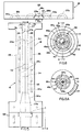
- each die mounting plate 38 which receives the die components generally designated C which comprise an integral part of the present invention. While the system described accommodates four sets of such die components C, which are more particularly illustrated in Figures 8-10, a fewer or greater number of die components C may be involved. Figures 8-10 particularly illustrate how each of the die components C is fabricated in a manner to facilitate its ready disassembly .
- each die component C includes an upper receiving member, generally designated 39, having a lower flange 40 ( Figure 9) received in a recessed opening 41 provided in a lower discharge member, generally designated 42, having a shouldered flange 43.
- the counterbores 44 ( Figure 6), provided in plate 38 receive the members 42 in the manner indicated, with each member 39 received in the bore 37 provided for it, as illustrated.
- Each of the members 39 comprises an outer ring, generally designated 39a, separated from a core, generally designated 39b, by radial ribs, generally designated 39c, which define a plurality of spaced apart elongate, segmental passages 45 surrounding core 39b.
- the configuration of passages 45, through which the mass is passed to a divergent frusto-conical passage 42a in the member 42, which communicates with the cylindrical discharge channel 42b in the lower end of member 42, will be presently described.
- Each core 39b is centrally bored as at 46 to receive a pin 47, the reduced threaded upper end 47a of which receives a flow dividing member, generally designated 48, having a threaded bore 48b.
- Each member 48 is formed with a conical portion 48a extending up into the die entrance channel 36 and terminating in a cylindrical portion 48c. Tapered portion 48a extends at an angle e from the axis of core 39b and the direction of flow z .
- pin 47 is threaded as at 47b to receive an internally threaded sleeve member 49 which extends into the divergent passage 42a and includes a cylindrical portion 49a and a conical portion 49b.
- a series of bored openings 50 provided in the portion 49b fixedly mount the elongate pins P, which extend from the passage 42a to the exit end of the discharge channel 42b and form the longitudinal perforations in the product expressed as a cylinder from the discharge channel 42b.
- each of the marginal walls of passages 45 is made up of radial and circumferential, downwardly and inwardly sloped surfaces 45a and 45b respectively, sloping at the same angle in a downward direction.
- the adjacent radial surfaces 45a of each rib 39c slope from a radial ridge-line 45c to the ends of adjacent reduced metering necks 45d in the passages 45 intermediate the ends of flow passages 45.
- Convergent downwardly and inwardly sloped surfaces 45b slope to form the opposite sides of each neck 45d, which, in plan, is generally oblong in configuration.
- passages 45 are similarly configured in an axial direction, except vertically reversed. They are formed by diverging radial and circumferential walls 54 and 54a, respectively, and circumferentially inner and outer vertical walls 55. Passages 45 are thus generally hour-glass shaped in vertical cross-section as shown in Figure 9.
- each of the angles e , f , g , h , i , j , k , and l are 15° or less so that no abrupt turns or corners are presented within which secondary flows can occur, and in which dead spots of material can accumulate.
- the passages 45 between ribs 39c are of the configuration disclosed and converge in this configuration down to each neck 45d. They then diverge outwardly in the same configuration to empty into convergent passage 42a.
- the ribs 39c are shown in cross-section in Figure 10 and, as shown have convergent upper, lower, and side surfaces.
- There is a pressure drop in the discharge channel 42b of each of the die components C which is far greater than the pressure drop anywhere else in the system.
- the pressure drop in discharge channel 42b is the only pressure drop which is significant in the present design wherein the pressure drop is less than in the prior art devices by about 50%.
- the manufacture of the manifold assembly M flow passages is greatly facilitated.
- the network of mating heat transfer passages can also readily be provided in the separate halves 26 to accommodate a recirculating heat transfer fluid which cools the unit and prevents heat buildup therein.
- the potentially explosive viscous mass which is continuously delivered to the inlet opening 70 feeds smoothly through the passages in the manifold without any abrupt changes in direction greater than 15°.
Landscapes
- Engineering & Computer Science (AREA)
- Mechanical Engineering (AREA)
- Manufacturing & Machinery (AREA)
- Chemical & Material Sciences (AREA)
- Organic Chemistry (AREA)
- Extrusion Moulding Of Plastics Or The Like (AREA)
- Processing And Handling Of Plastics And Other Materials For Molding In General (AREA)
- Manufacture, Treatment Of Glass Fibers (AREA)
- Glanulating (AREA)
Claims (12)
- Ein mit einer Mehrzahl von Stiften versehenes Gesenkbauteil (C) zur Aufnahme unter Druck stehenden extrudierten Materials aus einem Mischer oder einer anderen Strömungsquelle und zur Abgabe des Materials in zylindrischer Gestalt mit einer Mehrzahl von sich in axialer Richtung erstreckenden Perforationen, enthaltend:a) ein Gehäuse (Elemente 39, 42), mit einem Eingangskanal (36) und einem Ausgangskanal (42b),b) und eine Mehrzahl von länglichen Stiften (P), die sich in axialer Richtung in den Ausgangskanal (42b) erstrecken, um so bei der Abgabe des Materials die Perforationen auszubilden,dadurch gekennzeichnet, daßc) das Gehäuse einen Axialkern (39b) enthält, der mit dem Gehäuse über radial ausgerichtete Rippen (39c) verbunden ist, die strömungsoberseitig konvergierende Oberflächen (45a) aufweisen, wobei die Rippen eine Mehrzahl von sich in axialer Richtung erstreckenden, in Umfangsrichtung zwischen den Rippen angeordneten Durchgängen (45) bilden, durch die Werkstoffströme vom Eingangskanal (36) zum Ausgangskanal (42b) transportiert werden; undd) der Kern (39b) ein konisch vorstehendes Element (48) an seinem axial strömungsoberseitigen Ende aufweist, der in den fließenden Werkstoffstrom eindringt und diesen gleichmäßig auf die Durchgänge (45) verteilt.
- Gesenkbauteil nach Anspruch 1, dessen Eingangs- und Ausgangskanäle (36, 42b) sowie die sich in axialer Richtung erstreckenden Durchgänge (45) in einem Winkel in der Größenordnung von maximal etwa 15° von der Achse abweichen.
- Gesenkbauteil nach Anspruch 1, in dem der Kern (39b) einen im wesentlichen konischen vorspringenden Bereich (49b) an seinem axial strömungsabseitigen Ende aufweist und in dem sich eine Mehrzahl von sich in axialer Richtung erstreckenden länglichen Stiften (P) vom strömungsabseitigem, im wesentlichen konischen Bereich (49b) in den Abgabekanal (42b) erstreckt.
- Gesenkbauteil nach Anspruch 1, wobei die Durchgänge (45) in axialer Richtung im wesentlichen stundenglasförmig ausgebildet sind.
- Gesenkbauteil nach Anspruch 1, in dem die Durchgänge (45) axial konvergierende innere und äußere Umfangsflächen (45b) aufweisen, die mit axial konvergierenden inneren und äußeren Radialrippenflächen (45a) zur Bildung von segmentförmigen Öffnungen (Rücken 45d) zusammengefügt sind.
- Gesenkvorrichtung (M) enthaltend eine Mehrzahl von Gesenkbauteilen (C) entsprechend Anspruch 1 und weiterhin enthaltend ein Gesenkkanalblockelement (Verteilerhälften 26) mit einem Eingangskanal (27) kreisförmigen Querschnitts, der in einen Durchgang (28) mündet, der im Querschnitt die Form der Ziffer 8 aufweist (Fig. 13) und sich in ein Paar von getrennten, sich voneinander weghiegenden Zweigdurchgängen (30) aufteilt, die rechtwinklig zu ihrer Erstreckungsachse im Querschnitt kreisförmig sind (Fig. 14), wobei die Gesenkhauteile (C) strömungsabseitig gegenüber den Zweigdurchgängen (30) angeordnet sind und mit diesen in Verbindung stehen.
- Gesenkvorrichtung nach Anspruch 6, wobei der Kern (39b) eines jeden Gesenkbauteils (C) einen konisch vorspringenden Abschnitt (48a) an seinem axial strömungsoberseitigen Ende aufweist, der in den fließenden Werkstoffstrom eindringt und ihn gleichmäßig auf die Durchgänge 45 verteilt, während gleichzeitig die Bildung von sogenannten Totpunkten sowie die Entmischung vermieden werden, wobei die Zweigdurchgänge (30), der konisch vorspringende Abschnitt (48a), der Eingangs- und der Ausgangskanal (36, 42b) und axial sich erstreckende Durchgänge (45) in einem Winkel in der Größenordnung von höchstens etwa 15° von der Achse abweichen.
- Gesenkvorrichtung nach Anspruch 6, wobei der Durchgang (28), der in Form der Ziffer 8 gestaltet ist, durch einander gegenüberliegende Erhöhungen (28c) gebildet wird, die sich schrittweise einander annähern, um so den Durchgang (28), der in Form der Ziffer 8 gestaltet ist, in die Zweigdurchgänge (30) einmünden zu lassen.
- Gesenkvorrichtung nach Anspruch 6, wobei die Zweigdurchgänge (30) sich jeweils um einen bestimmten Radius biegen, während sie sich voneinander entfernen, um sich dann wieder zurückzubiegen, und zwar um den Radius (r), der mindestens das Achtfache des Radius' (r') der Zweigdurchgänge (30) beträgt.
- Gesenkvorrichtung nach Anspruch 9, wobei die Zweigdurchgänge (30) nach dem Zurückbiegen in Durchgänge (30b) einmünden, die wiederum im Querschnitt entsprechend der Ziffer 8 gestaltet sind (Fig. 16), und die sich in Durchgänge kreisförmigen Querschnitts (Fig. 18) aufteilen.
- Gesenkvorrichtung nach Anspruch 8, wobei das Gesenkkanalblockelement aus zwei sich ergänzenden Verteilerhälften (26) besteht, wobei der Eingangskanal (27), die Durchgänge (28) und die Zweigdurchgänge (30) jeweils zur Hälfte in jeder dieser Hälften ausgebildet sind, und wobei die Rücken in jeder dieser Hälften angeordnet sind.
- Gesenkvorrichtung nach Anspruch 6, wobei der Kern (39b) einen konisch vorspringenden Abschnitt (49b) an seinem strömungsabseitigen Ende aufweist und wobei die umgebende Hülle ein Element (42) mit einem konvergierenden Durchgang (42a) der gleichen Neigung wie der konisch vorspringende Abschnitt (49b) enthält, wobei der Abschnitt (49b) in den Durchgang (42a) hineinragt und die Stifte (P) so befestigt sind, daß sie vom genannten strömungsabseitigen konischen Abschnitt (49b) in Achsrichtung parallel zueinander vorstehen.
Applications Claiming Priority (2)
| Application Number | Priority Date | Filing Date | Title |
|---|---|---|---|
| US07/237,415 US4945807A (en) | 1988-08-29 | 1988-08-29 | Method and apparatus for processing potentially explosive and sensitive materials for forming longitudinally perforated extrudate strands |
| US237415 | 1988-08-29 |
Publications (3)
| Publication Number | Publication Date |
|---|---|
| EP0357004A2 EP0357004A2 (de) | 1990-03-07 |
| EP0357004A3 EP0357004A3 (de) | 1991-01-09 |
| EP0357004B1 true EP0357004B1 (de) | 1995-04-12 |
Family
ID=22893622
Family Applications (1)
| Application Number | Title | Priority Date | Filing Date |
|---|---|---|---|
| EP89115944A Expired - Lifetime EP0357004B1 (de) | 1988-08-29 | 1989-08-29 | Verfahren und Vorrichtung zur Bearbeitung von potentiell explosiven und empfindlichen Materialien zum Formen von länglichen perforierten extrudierten Strängen |
Country Status (4)
| Country | Link |
|---|---|
| US (1) | US4945807A (de) |
| EP (1) | EP0357004B1 (de) |
| JP (1) | JPH02160686A (de) |
| DE (1) | DE68922162T2 (de) |
Families Citing this family (11)
| Publication number | Priority date | Publication date | Assignee | Title |
|---|---|---|---|---|
| US5055022A (en) * | 1990-03-22 | 1991-10-08 | Hoover Universal, Inc. | Multiple parison extrusion device for producing laminar articles |
| US5346713A (en) * | 1993-01-21 | 1994-09-13 | Leader Robert G | Method for forming a compressed bar from an oil seed crop |
| US5486049A (en) * | 1994-01-28 | 1996-01-23 | Nestec S.A. | Apparati for mixing fluid substances |
| US5620205A (en) * | 1994-03-14 | 1997-04-15 | Morton International, Inc. | Gas generation and ignition system for airbag inflation |
| US5776534A (en) * | 1996-04-03 | 1998-07-07 | General Mills, Inc. | Food apparatus for forming multiple colored extrudates and method of preparation |
| US5919509A (en) * | 1997-05-01 | 1999-07-06 | General Mills, Inc. | Method and apparatus for producing multiple food extrudates |
| DE10009819A1 (de) * | 2000-03-01 | 2001-09-06 | Trw Airbag Sys Gmbh & Co Kg | Verfahren zur Herstellung von Treibstoff-Formlingen |
| IT1319599B1 (it) * | 2000-12-20 | 2003-10-20 | Rosaldo Fare | Testa di melt-blown e procedimento ad alimentazione controllata per laproduzione di fibrille di materiale polimerico |
| US20060076703A1 (en) * | 2004-10-13 | 2006-04-13 | Looman Ernest W Jr | Double flow channel for an extruder head |
| CN103124591B (zh) * | 2010-09-30 | 2015-06-03 | 伊奎聚合物有限公司 | 混合方法和可用于其的装置 |
| DE102019009151B3 (de) * | 2019-08-06 | 2020-09-10 | Kautex Maschinenbau Gmbh | Schmelzeverteiler |
Family Cites Families (24)
| Publication number | Priority date | Publication date | Assignee | Title |
|---|---|---|---|---|
| US1744130A (en) * | 1928-03-19 | 1930-01-21 | Dunlop Tire & Rubber Corp | Apparatus for extruding tubes |
| US2491588A (en) * | 1945-04-19 | 1949-12-20 | Hercules Powder Co Ltd | Extrusion die |
| US2944287A (en) * | 1956-08-28 | 1960-07-12 | Phillips Petroleum Co | Apparatus for and method of extruding plastic materials |
| US3381336A (en) * | 1966-06-20 | 1968-05-07 | Stanley C. Wells | Melt spinning extrusion head system |
| US3416190A (en) * | 1966-06-28 | 1968-12-17 | Mehnert Gottfried | Diehead |
| GB1207952A (en) * | 1966-07-06 | 1970-10-07 | Mini Of Technology | Improvements in or relating to extrusion apparatus |
| US3561053A (en) * | 1967-05-15 | 1971-02-09 | Owens Illinois Inc | Extrusion device |
| US3574889A (en) * | 1968-11-18 | 1971-04-13 | Charles H Hire | Multiport extruding die |
| US3618162A (en) * | 1969-10-02 | 1971-11-09 | Usm Corp | Plastic pelletizer underwater pelletizing head |
| US3884452A (en) * | 1972-09-25 | 1975-05-20 | Manbritt Ind Inc | Blow-molding plasticizing manifold |
| DE2316538C3 (de) * | 1973-04-03 | 1982-05-06 | Dynamit Nobel Ag, 5210 Troisdorf | Verfahren zur Herstellung von Gudol- Pulver |
| DE2461646C2 (de) * | 1974-12-27 | 1984-01-05 | Dynamit Nobel Ag, 5210 Troisdorf | Verfahren zur Herstellung von Treibladungspulvern |
| DE2605481A1 (de) * | 1975-02-15 | 1976-08-26 | Icoa | Verfahren und vorrichtung zur herstellung polykapillarer elemente |
| US3960993A (en) * | 1975-02-27 | 1976-06-01 | The United States Of America As Represented By The Secretary Of The Navy | Method for extruding solventless gun powder |
| US4032279A (en) * | 1975-09-08 | 1977-06-28 | The B. F. Goodrich Company | Extrusion adapter |
| CH590122A5 (de) * | 1975-09-17 | 1977-07-29 | Netstal Ag Maschf Giesserei | |
| FR2325491A1 (fr) * | 1975-09-25 | 1977-04-22 | Poudres & Explosifs Ste Nale | Procede de boudinage des compositions pyrotechniques, et boudineuse a vis |
| US4076477A (en) * | 1975-12-08 | 1978-02-28 | Grandview Industries Limited | Multiple extrusion apparatus |
| DE2847627A1 (de) * | 1978-01-04 | 1979-07-05 | Plasticisers Ltd | Extrusionsmatrize oder -verteilerkopf |
| JPS57143507A (en) * | 1981-02-18 | 1982-09-04 | Toray Ind Inc | Spinneret device for conjugate fiber |
| DE3372337D1 (en) * | 1982-12-06 | 1987-08-13 | Windmoeller & Hoelscher | Method and device for the formation and rearranging of partial streams from extruded thermoplastic and/or elastomeric materials |
| US4585600A (en) * | 1984-11-28 | 1986-04-29 | Hercules Incorporated | Extrusion, conveyance, and cutting system |
| US4767577A (en) * | 1985-10-03 | 1988-08-30 | Mueller Dietmar | Process and apparatus for producing plastic-bound propellant powders and explosives |
| US4744669A (en) * | 1986-10-23 | 1988-05-17 | Baker Perkins, Inc. | Mixing and extruding apparatus and methods |
-
1988
- 1988-08-29 US US07/237,415 patent/US4945807A/en not_active Expired - Lifetime
-
1989
- 1989-08-29 JP JP1222759A patent/JPH02160686A/ja active Pending
- 1989-08-29 EP EP89115944A patent/EP0357004B1/de not_active Expired - Lifetime
- 1989-08-29 DE DE68922162T patent/DE68922162T2/de not_active Expired - Fee Related
Also Published As
| Publication number | Publication date |
|---|---|
| DE68922162D1 (de) | 1995-05-18 |
| US4945807A (en) | 1990-08-07 |
| EP0357004A2 (de) | 1990-03-07 |
| DE68922162T2 (de) | 1995-08-31 |
| JPH02160686A (ja) | 1990-06-20 |
| EP0357004A3 (de) | 1991-01-09 |
Similar Documents
| Publication | Publication Date | Title |
|---|---|---|
| EP0357004B1 (de) | Verfahren und Vorrichtung zur Bearbeitung von potentiell explosiven und empfindlichen Materialien zum Formen von länglichen perforierten extrudierten Strängen | |
| US5096406A (en) | Extruder assembly for composite materials | |
| FI68017C (fi) | Anordning foer extrudering av expanderbart cellbildande termoplastiskt material | |
| CA2032480C (en) | Continuous extrusion apparatus | |
| US3941535A (en) | Extrusion device | |
| US3956438A (en) | Process for extruding a partially foamed thermoplastic product | |
| EP0302621B1 (de) | Lochplatte für die Unterwassergranulierung von Kunststoffsträngen mit hoher Schmelzströmungsgeschwindigkeit | |
| EP1091798B1 (de) | Mischvorrichtung | |
| US3782870A (en) | Apparatus for extruding a partially foamed thermoplastic product | |
| EP0960715A2 (de) | Schneckenapparat und Verfahren zum Zuführen von faserverstärkter Kunststoffschmelze unter Verwendung dieses Apparates | |
| CA2029215A1 (en) | Extrusion die assembly | |
| US4798472A (en) | Extruder screw with balanced flights of different functional sections | |
| US4687430A (en) | Co-extrusion die | |
| US9750268B1 (en) | Grain bulk densifying die apparatus and method | |
| US4350657A (en) | Low-energy extruder-pump system | |
| US4461734A (en) | Process for plasticization and pumping of low bulk density plastics | |
| EP4219117A2 (de) | Polymerkoextrusionskopf mit einer zweikanaldüse | |
| US5129304A (en) | Method and apparatus for processing potentially explosive and sensitive materials for forming longitudinally perforated extrudate strands | |
| CA2217374A1 (en) | Extensional flow mixer | |
| US3932102A (en) | Spiral design pipehead | |
| US5599098A (en) | Extruder screw with multiple flighting | |
| US5641227A (en) | Extrusion and refining apparatus and method | |
| US4444507A (en) | Apparatus and method for melting and conveying plasticated material | |
| US4413968A (en) | Extrusion die metering device | |
| US5853770A (en) | Coextrusion die component system |
Legal Events
| Date | Code | Title | Description |
|---|---|---|---|
| PUAI | Public reference made under article 153(3) epc to a published international application that has entered the european phase |
Free format text: ORIGINAL CODE: 0009012 |
|
| AK | Designated contracting states |
Kind code of ref document: A2 Designated state(s): DE FR GB |
|
| PUAL | Search report despatched |
Free format text: ORIGINAL CODE: 0009013 |
|
| AK | Designated contracting states |
Kind code of ref document: A3 Designated state(s): DE FR GB |
|
| 17P | Request for examination filed |
Effective date: 19910708 |
|
| 17Q | First examination report despatched |
Effective date: 19930209 |
|
| GRAA | (expected) grant |
Free format text: ORIGINAL CODE: 0009210 |
|
| AK | Designated contracting states |
Kind code of ref document: B1 Designated state(s): DE FR GB |
|
| REF | Corresponds to: |
Ref document number: 68922162 Country of ref document: DE Date of ref document: 19950518 |
|
| ET | Fr: translation filed | ||
| PGFP | Annual fee paid to national office [announced via postgrant information from national office to epo] |
Ref country code: GB Payment date: 19950818 Year of fee payment: 7 |
|
| PLBE | No opposition filed within time limit |
Free format text: ORIGINAL CODE: 0009261 |
|
| STAA | Information on the status of an ep patent application or granted ep patent |
Free format text: STATUS: NO OPPOSITION FILED WITHIN TIME LIMIT |
|
| 26N | No opposition filed | ||
| PG25 | Lapsed in a contracting state [announced via postgrant information from national office to epo] |
Ref country code: FR Effective date: 19960430 |
|
| PG25 | Lapsed in a contracting state [announced via postgrant information from national office to epo] |
Ref country code: DE Effective date: 19960501 |
|
| REG | Reference to a national code |
Ref country code: FR Ref legal event code: ST |
|
| PG25 | Lapsed in a contracting state [announced via postgrant information from national office to epo] |
Ref country code: GB Effective date: 19960829 |
|
| GBPC | Gb: european patent ceased through non-payment of renewal fee |
Effective date: 19960829 |