EP0355622A2 - Method and apparatus for the surface pretreatment of a moulded single or multilayered material by electric corona discharge - Google Patents
Method and apparatus for the surface pretreatment of a moulded single or multilayered material by electric corona discharge Download PDFInfo
- Publication number
- EP0355622A2 EP0355622A2 EP89114891A EP89114891A EP0355622A2 EP 0355622 A2 EP0355622 A2 EP 0355622A2 EP 89114891 A EP89114891 A EP 89114891A EP 89114891 A EP89114891 A EP 89114891A EP 0355622 A2 EP0355622 A2 EP 0355622A2
- Authority
- EP
- European Patent Office
- Prior art keywords
- corona discharge
- aerosol
- electrodes
- molding material
- electrically conductive
- Prior art date
- Legal status (The legal status is an assumption and is not a legal conclusion. Google has not performed a legal analysis and makes no representation as to the accuracy of the status listed.)
- Granted
Links
Images


Classifications
-
- H—ELECTRICITY
- H01—ELECTRIC ELEMENTS
- H01T—SPARK GAPS; OVERVOLTAGE ARRESTERS USING SPARK GAPS; SPARKING PLUGS; CORONA DEVICES; GENERATING IONS TO BE INTRODUCED INTO NON-ENCLOSED GASES
- H01T19/00—Devices providing for corona discharge
-
- B—PERFORMING OPERATIONS; TRANSPORTING
- B29—WORKING OF PLASTICS; WORKING OF SUBSTANCES IN A PLASTIC STATE IN GENERAL
- B29C—SHAPING OR JOINING OF PLASTICS; SHAPING OF MATERIAL IN A PLASTIC STATE, NOT OTHERWISE PROVIDED FOR; AFTER-TREATMENT OF THE SHAPED PRODUCTS, e.g. REPAIRING
- B29C59/00—Surface shaping of articles, e.g. embossing; Apparatus therefor
- B29C59/10—Surface shaping of articles, e.g. embossing; Apparatus therefor by electric discharge treatment
- B29C59/12—Surface shaping of articles, e.g. embossing; Apparatus therefor by electric discharge treatment in an environment other than air
-
- C—CHEMISTRY; METALLURGY
- C21—METALLURGY OF IRON
- C21D—MODIFYING THE PHYSICAL STRUCTURE OF FERROUS METALS; GENERAL DEVICES FOR HEAT TREATMENT OF FERROUS OR NON-FERROUS METALS OR ALLOYS; MAKING METAL MALLEABLE, e.g. BY DECARBURISATION OR TEMPERING
- C21D1/00—General methods or devices for heat treatment, e.g. annealing, hardening, quenching or tempering
- C21D1/34—Methods of heating
- C21D1/38—Heating by cathodic discharges
-
- Y—GENERAL TAGGING OF NEW TECHNOLOGICAL DEVELOPMENTS; GENERAL TAGGING OF CROSS-SECTIONAL TECHNOLOGIES SPANNING OVER SEVERAL SECTIONS OF THE IPC; TECHNICAL SUBJECTS COVERED BY FORMER USPC CROSS-REFERENCE ART COLLECTIONS [XRACs] AND DIGESTS
- Y10—TECHNICAL SUBJECTS COVERED BY FORMER USPC
- Y10S—TECHNICAL SUBJECTS COVERED BY FORMER USPC CROSS-REFERENCE ART COLLECTIONS [XRACs] AND DIGESTS
- Y10S422/00—Chemical apparatus and process disinfecting, deodorizing, preserving, or sterilizing
- Y10S422/907—Corona or glow discharge means
Definitions
- the invention relates to a method for the surface pretreatment of single- or multi-layered molding material by means of an electrical corona discharge, which runs between live electrodes and a grounded counter electrode, between which the single- or multi-layered molding material is located, and a device for surface pretreatment of the molding material.
- a corona pretreatment takes place handling a plastic film web in such a way that the film web is subjected to a corona application on the top and / or the bottom, which results in different pretreatment intensities.
- the film web to be treated is passed over an electrically grounded roller and the electrical charges are applied by applying an electrical corona discharge to the side of the film web facing away from the roller surface, which is generated by applying a high-frequency alternating current of high voltage to an electrode arranged at a distance from the roller .
- the pretreatment is generally carried out in air at atmospheric pressure.
- US Pat. No. 3,142,630 describes a method for increasing the adhesion, in which a film web is passed through a non-ionizing liquid and is exposed to a corona discharge in the liquid.
- This liquid can be, for example, a transformer cooling oil, vegetable oil or another pure oil, free of impurities, which is largely electrically non-conductive.
- GB-PS 938 325 describes a process for the pretreatment of thermoplastic films, in which an electrical corona discharge takes place on the surface in a nitrogen atmosphere.
- the nitrogen is introduced into the corona discharge zone via distribution lines through hollow electrode lines.
- organic compounds from the group of polymerizable organic compounds, non-polymerizable organic compounds with replaceable hydrogen atoms, and perhalogenated hydrogen are introduced into the corona discharge zone through distribution lines in order to spread the surface of film webs or objects Modify polymers.
- a device is known from Japanese patent specification 17 747/73 in which a film surface is exposed to a corona discharge.
- the electrode connected to the generator consists of porous sintered metals and several metal meshes.
- the discharge electrode is shaped in such a way that liquid which is supplied to it is collected and stored.
- the stored liquid is converted into the gas phase and emerges from the porous sintered metals in the form of gas particles. which move under the influence of the electric field lines of the corona discharge on the film surface.
- the object of the invention is to design a method and a device as described in the introduction in such a way that single-layer or multilayer molding materials are pretreated with reactive substances in liquid form can be, these substances can also be applied as special layers for finishing the surfaces of the molding materials on these.
- This object is achieved according to the invention by the method described at the outset in such a way that the corona discharge is directed onto a layer of the molding material which consists of a metallic material or contains metallic or other electrically conductive particles in a plastic matrix, and that into the corona discharge zone by means of a Air or gas stream an aerosol, formed by the atomization of a liquid, is introduced.
- a device for the surface pretreatment of electrically conductive molding material by means of an electrical corona discharge, with electrodes acted upon by a generator with a high-frequency alternating current of high voltage and arranged at a distance from an earthed counterelectrode, is characterized in that the electrodes encased with dielectric material have one first corona discharge device are shielded from the environment by a housing which is connected via a line to an atomizing device for atomizing liquid to form a floating aerosol, that the grounded counter electrode has a metallic surface has and that a fan adjustable in the throughput is connected to the atomizer device and conveys the carrier gas for the aerosol through the atomizer device into the corona discharge device.
- the atomizer device consists of a piezoelectrically operating ultrasonic vibration system or the atomizer device has two-component atomizer nozzles operating at the speed of sound.
- the corona discharge triggers reaction mechanisms that cause a chemical surface modification of the treated molding material.
- active centers in the form of functional groups and radicals are generated on the treated surface of the molding material, which act as reactants for the substances applied to subsequent processes.
- polymerizable or crosslinking layers can also be applied to the surface in a single process step.
- the molding materials can be purely metallic single-layer foils, e.g. B.
- aluminum foils such as those used in composite foil production, or elec Plastic substrates with a tric conductive finish, such as film webs, which are partially or fully printed with printing inks containing metal pigments or are designed with vapor-deposited metal layers.
- the film webs can be equipped with layers of dispersions containing magnetic particles in magnetic recording media or with soot-filled layers in thermal writing tapes.
- metallic, non-insulated high-voltage electrodes / grounded insulated counterelectrode can be used in the corona treatment of pure plastic materials, this combination cannot be used in the invention; instead, dielectrically insulated high-voltage electrodes are used as counterelectrode together with a grounded metal roller. Only this electrode configuration allows the formation of the electrical field strengths required for plasma ignition by the corona discharge in the case of electrically conductive molding materials.
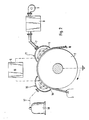
- FIG. 1 shows a device consisting of a roller 10, over which a film web 1 to be treated with an electrically conductive layer 3 is guided, and a first corona discharge device 11, which comprises a housing 6 and electrodes 4, which are connected to a generator 5 .
- the electrodes 4 are, for example, coated with a dielectric material 29 metallic stranded wires 0.8 mm in diameter and a thickness of the dielectric layer, for. B. a silicone rubber layer of 2 mm, so that the diameter of the coated electrodes is 4.8 mm.
- the roller consists of a metallic roller core 2 without a dielectric coating. The roller core 2 is grounded so that the roller 10 is the counter electrode to the electrical 4 of the corona discharge device 11 forms.
- the distance between the electrodes 4 and the film web 1 is up to about 2 mm.
- the roller 10 rotates in the direction of arrow A.
- the generator 5 applies a high-frequency alternating current of high voltage to the electrodes 4.
- an electrical corona discharge is ignited between the grounded roller 10 and the electrodes 4, through whose field lines, which are indicated schematically in FIG. 1, the film web 1 is passed.
- the electrodes 4 are shielded from the surroundings by the housing 6, which is connected to an atomizer device 8 via a line 7, for example a rigid pipeline or a hose line or other flexible line.
- the line 7 is connected to a pipe socket 12 of the housing 6 on the one hand and to a pipe socket 13 of the atomizer device 8 on the other hand.
- the liquid to be introduced is atomized into a suspended aerosol, which is transported into the corona discharge device 11 by means of an air or carrier gas stream supplied by a blower 9 which can be regulated in terms of the throughput.
- the atomizer device 8 is a two-substance atomizer nozzle which is known per se, in which the liquid is torn into tiny droplets by the carrier gas escaping at the speed of sound, for example air, or piezoelectric ultrasonic oscillation systems which, through their vibrations, cause the carrier gas or vibrate the air to the liquid ability to tear into tiny droplets.
- the fan 9 is flanged directly to the atomizer device 8.
- the aerosol introduced or blown into the housing 6 of the corona discharge device 11 is distributed uniformly in the interior of the housing 6 and migrates along the field lines which run from the electrodes 4 in the direction of the film web 1 to the film surface and is deposited there. This results in a very uniform wetting or coating of the film web 1 with the aerosol, which results in a very uniform modification of the surface properties of the film web.
- the electrodes 4 have an open design as discharge electrodes, ie an electrode shape with a sufficiently large free cross section between the individual electrodes. For this purpose, inter alia, axially parallel to the circumference of the roller 10 arranged dielectric coated wire electrodes have proven effective.
- special coatings can be applied to the film web. In many cases, extremely thin layers are sufficient to change the surface properties of a film as desired, such as antistatic, abhesiveness, abrasion resistance, static and sliding friction behavior, barrier behavior, adhesion, adhesion promotion.
- monomers, dispersions, solutions of low and / or high molecular weight components and colloidal systems which can be used in aqueous form or dissolved in solvents, these are suitable, inter alia, for the production of the aerosols.
- the electrodes 4 of the corona discharge device 11 are acted upon by the generator 5 with an alternating voltage between 5000 V and 25000 V, the alternating voltage present between the electrodes 4 and the roller 10 or its roller core 2 as a grounded counter electrode being proportional to the transport speed of the film web 1 the corona discharge device 11 is set. Studies have shown that the applied alternating voltage supplied by the generator 5 must be increased with a higher transport speed in order to achieve a uniform surface modification of the film web 1.
- FIG. 2 shows an embodiment of the invention which is constructed similarly to FIG. 1 and in which a second corona discharge device 15 is arranged in front of the first corona discharge device 11 with an electrically conductive layer 3 in the transport direction of the film web 1.
- the electrodes 14 of the second corona discharge device are let through a housing 16 shields, which is connected via a line 17 to a gas container 18.
- the electrodes 14 are, for example, steel stranded wires of 0.8 mm diameter coated with a dielectric material 30.
- the thickness of the material 30 is 2 mm, the material being a silicone rubber.
- the generator 5 feeds both the electrodes 4 of the first corona discharge device 11 and the electrodes 14 of the second corona discharge device 15.
- the other components of this arrangement such as the atomizer device 8 and the blower 9, correspond to the corresponding components of the arrangement according to FIG. 1 and become therefore not described again.
- a combined pretreatment of the film web 1 takes place, which is initially subjected to a corona discharge in a reactive atmosphere in the area of the second corona discharge device 15, ie a surface modification of the film web 1 before the treatment by applying an aerosol to the film surface by means of the corona discharge in the first corona discharge device 11.
- a gas from the gas container 18 into the second corona discharge device 15 a coordinated modification or activation of the to treating film web in the corona discharge zone of the first corona discharge device 11 are made.
- nitrogen or other nitrogenous gaseous compounds can be used as the reactivation gas.
- the gas container 18 is connected to the housing 16 of the second corona discharge device 15 via a line 17.
- the pressure of the gas flowing out of the gas container 18 is usually regulated by a pressure reducing valve (not shown in more detail).
- a pressure reducing valve not shown in more detail.
- Figure 2 it is shown that the discharge electrodes 4 and 14 of the two corona discharge devices 11 and 15 are supplied with voltage by the single generator 5, but an arrangement is also possible in which the electrodes of each corona discharge device are supplied with high voltage by their own generator .
- FIG. 3 shows an embodiment of the invention in which two devices corresponding to the device shown in FIG. 1 are arranged along the circumference of the roller 10.
- the first corona discharge device 11 with the connected atomizer device 8 and the blower 9 largely corresponds to the device as was described with reference to FIG. 1.
- a third corona discharge device 19 with electrodes 20 is provided after the first corona discharge device 11, the housing 21 of which encloses the electrodes 20.
- the electrodes 20 have a jacket made of dielectric material 31 and are constructed in the same way as the electrodes of the first and second corona discharge devices.
- the housing 20 is connected via a pipe socket and a line 22 to a pipe socket of an atomizer device 23, to which a gas container 24 is connected.
- a carrier gas for the aerosol, which is generated in the atomizing device 23 from the treatment liquid, is stored in the gas container 24.
- various noble gases can also be considered as carrier gases.
- the electrodes 4 and 20 of the first and third corona discharge devices 11 and 19 are connected to the common generator 5. However, it is also possible with this device that each of the corona discharge devices is supplied with voltage via a separate generator.
- Either air or a gas can be blown into the atomizing device 8 via the blower 9, which then serves as carrier gas for the respective aerosol, which is fed into the corona discharge device 11.
- the blower 9 which then serves as carrier gas for the respective aerosol, which is fed into the corona discharge device 11.
- this device permits versatile surface modifications of the film web 1.
- the film web 1 can consist of polypropylene, polyester, and also of polyvinyl chloride. Possible transport speeds for the film web 1 are in the range from 20 to 200 m / min.
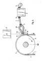
- FIG. 4 shows a modified embodiment of the device, which differs from the devices according to FIGS. 1 to 3 in such a way that the aerosol generated in the atomizing device 8 is blown into a wide-slot air nozzle 25 by the blower 9 via the line 7.
- the line 7 is connected via pipe sockets 12 and 13 to the air nozzle 25 and the atomizing device 8.
- the grounded counter electrode to the discharge electrodes 27 forms the roll core 2 of the roll 10, over the partial circumference of which the film web 1 to be treated, which has an electrically conductive layer 3, is guided.
- the generator 5 acts on the electrodes 27 with a high-frequency alternating current of high voltage.
- the aerosol emerging from the air nozzle 25 goes directly into the field of the corona discharge.
- the aerosol droplets are held in the electric field and prevented from uncontrolled vagabonding into the surroundings, which is reflected both in a further improvement in the uniformity of the layers applied to the substrate and in a largely loss-free use of the amount of aerosol offered.
- the device with air nozzle shown in FIG. 4 can of course also be used in the configuration shown in FIG. 3 instead of any of the devices used there.
- the method and the devices can be used for the surface modification of partially or fully electrically conductive coated, printed or metal-coated plastic films and of pure metal films.
- Plastic films, papers, threads, fibers, fabrics and knitted fabrics, in the matrix of which metallic or other electrically conductive particles are incorporated, can also be surface-modified.
- the pretreatment can be carried out both on the conductive and on the non-conductive substrate surface.
- the method according to the invention for modifying electrically conductive plastic surfaces with the aid of corona discharges expands the possibilities of chemical modification of surfaces of plastic mate by including liquids, especially in the form of aerosols, in the corona discharge processes rialien considerably.
- the subsequent finishing steps such as coating, printing, laminating, painting, coordinated surface modifications, can be adjusted or chemically active layers can be applied to the treated, electrically conductive plastic surfaces.
- a selection of substances that can be introduced as aerosols into the corona discharge devices is compiled in a table below.
- the table shows the usability of the individual substances and the type of surface modification of the plastic that can be achieved. This selection makes no claim to completeness and does not limit the invention, since in principle all substances which form aerosols and which can modify the plastic surfaces in the desired manner can be used.
Landscapes
- Chemical & Material Sciences (AREA)
- Engineering & Computer Science (AREA)
- Physics & Mathematics (AREA)
- Metallurgy (AREA)
- Plasma & Fusion (AREA)
- Thermal Sciences (AREA)
- Mechanical Engineering (AREA)
- Toxicology (AREA)
- Materials Engineering (AREA)
- Health & Medical Sciences (AREA)
- Organic Chemistry (AREA)
- Crystallography & Structural Chemistry (AREA)
- Application Of Or Painting With Fluid Materials (AREA)
- Treatments Of Macromolecular Shaped Articles (AREA)
Abstract
Zur Oberflächenvorbehandlung von elektrisch leitenden Formmaterialien, wie Metallfolienbahnen oder Kunststoffolien, in deren Polymermatrix elektrisch leitfähige Partikel eingelagert sind, mittels elektrischer Koronaentladung ist eine Vorrichtung mit einem Generator 5 und einer Koronaentladungseinrichtung 11 vorgesehen. Der Generator beaufschlagt die von dielektrischem Material ummantelten Entladungselektroden 4 der Koronaentladungseinrichtung 11 mit einem hochfrequenten Wechselstrom hoher Spannung. Als geerdete metallische Gegenelektrode dient der Metallkern 2 einer Walze 10, über deren metallischen Umfang eine Folienbahn 1 transportiert wird. Ein Gehäuse 6 umschließt die Elektroden 4 der Koronaentladungseinrichtung 11 und ist über eine Leitung 7 mit einer Zerstäubereinrichtung 8 verbunden, in der eine Flüssigkeit zu einem schwebfähigen Aerosol mittels eines piezoelektrisch arbeitenden Ultraschallschwingsystems oder durch mit Schallgeschwindigkeit arbeitenden Zweistoff-Zerstäuberdüsen zerstäubt wird. Ein in der Durchsatzmenge regulierbares Gebläse 9 ist an die Zerstäubereinrichtung 8 angeschlossen und befördert das Trägergas, beispielsweise Luft, für das Aerosol durch die Zerstäubereinrichtung hindurch in die Koronaentladungseinrichtung 11.A device with a generator 5 and a corona discharge device 11 is provided for the surface pretreatment of electrically conductive molded materials, such as metal foil webs or plastic films, in the polymer matrix of which electrically conductive particles are embedded, by means of electrical corona discharge. The generator applies a high-frequency alternating current of high voltage to the discharge electrodes 4 of the corona discharge device 11 encased by dielectric material. The metal core 2 of a roller 10 serves as the grounded metallic counterelectrode, and a foil web 1 is transported over the metallic circumference thereof. A housing 6 encloses the electrodes 4 of the corona discharge device 11 and is connected via a line 7 to an atomizer device 8, in which a liquid is atomized to a suspended aerosol by means of a piezoelectric ultrasonic oscillation system or by means of two-substance atomizing nozzles operating at the speed of sound. A blower 9, which can be regulated in terms of the throughput, is connected to the atomizer device 8 and conveys the carrier gas, for example air, for the aerosol through the atomizer device into the corona discharge device 11.
Es können noch weitere Koronaentladungseinrichtungen vorhanden sein, in die ein Aerosol einer anderen Flüssigkeit oder nur ein reaktives Gas eingespeist werden. 
Description
Die Erfindung betrifft ein Verfahren zur Oberflächenvorbehandlung von ein- oder mehrschichtigem Formmaterial mittels einer elektrischen Koronaentladung, die zwischen spannungsführenden Elektroden und einer geerdeten Gegenelektrode abläuft, zwischen denen das ein- oder mehrschichtige Formmaterial sich befindet, sowie eine Vorrichtung zur Oberflächenvorbehandlung des Formmaterials.The invention relates to a method for the surface pretreatment of single- or multi-layered molding material by means of an electrical corona discharge, which runs between live electrodes and a grounded counter electrode, between which the single- or multi-layered molding material is located, and a device for surface pretreatment of the molding material.
In vielen Fällen bereitet die normalerweise glatte Oberfläche von Formmaterialien aus Kunststoffen, insbesondere von Folien, insofern Schwierigkeiten, als die Folienbahnen mit extrem gutem Schlupf leicht dazu neigen, beim Aufrollen auf einen Wickel zu teleskopieren. Weitere Schwierigkeiten aufgrund der glatten Oberflächen von Folien bzw. Formmaterialien ergeben sich bei der Veredelung dieser Materialien, zur Steigerung der Adhäsion von Druckfarben, Lacken, Klebern, aufgedampften Metallen und dergleichen. Um diese zu überwinden, gehört es zum Stand der Technik, chemisch-physikalische Oberflächemodifizierungen von Kunststoffen vorzunehmen, insbesondere von Folien. Ein grundsätzliches Verfahren, das nur Veränderungen auf der Kunststoffoberfläche herbeiführt, besteht in einer Vorbehandlung der Kunststoffoberfläche durch eine elektrische Koronaentladung. So erfolgt nach der DE-OS 32 47 795 eine Koronavorbe handlung einer Kunststoff-Folienbahn in der Weise, daß die Folienbahn auf der Oberseite und/oder der Unterseite einer Koronabeaufschlagung unterzogen wird, die unterschiedliche Vorbehandlungsintensitäten ergibt. Hierzu wird die zu behandelnde Folienbahn über eine elektrisch geerdete Walze geführt und die elektrischen Ladungen durch Beaufschlagen der der Walzenoberfläche abgewandten Seite der Folienbahn mit einer elektrischen Koronaentladung vorgenommen, die durch das Anlegen eines hochfrequenten Wechselstroms hoher Spannung an eine im Abstand zur Walze angordnete Elektrode erzeugt wird. Die Vorbehandlung erfolgt im allgemeinen unter Luft bei Atmosphärendruck.In many cases, the normally smooth surface of molded materials made of plastics, in particular films, is difficult in that the film webs with extremely good slippage tend to telescope when rolled up on a roll. Further difficulties due to the smooth surfaces of foils or molding materials arise in the refinement of these materials, in order to increase the adhesion of printing inks, lacquers, adhesives, vapor-deposited metals and the like. In order to overcome this, it is part of the prior art to carry out chemical-physical surface modifications of plastics, in particular of foils. A basic process that only brings about changes on the plastic surface consists in pretreating the plastic surface by means of an electrical corona discharge. According to DE-OS 32 47 795, a corona pretreatment takes place handling a plastic film web in such a way that the film web is subjected to a corona application on the top and / or the bottom, which results in different pretreatment intensities. For this purpose, the film web to be treated is passed over an electrically grounded roller and the electrical charges are applied by applying an electrical corona discharge to the side of the film web facing away from the roller surface, which is generated by applying a high-frequency alternating current of high voltage to an electrode arranged at a distance from the roller . The pretreatment is generally carried out in air at atmospheric pressure.
Die ständig steigenden Forderungen des Marktes nach Produkten mit verbesserten Oberflächeneigenschaften führten auch zur Entwicklung von Verfahren unter Einsatz von chemisch reaktionsfähigen Substanzen, die beispielsweise bestimmte chemische Bindungen in der Oberfläche aufbrechen und dadurch die Oberflächeneigenschaften von Kunststoffen verändern. In der US-PS 3,142,630 ist ein Verfahren zur Vergrößerung der Adhäsion beschrieben, bei dem eine Folienbahn durch eine nicht-ionisierende Flüssigkeit geführt wird und in der Flüssigkeit einer Koronaentladung ausgesetzt wird. Diese Flüssigkeit kann beispielsweise ein Transformatorkühlöl, pflanzliches Öl oder ein sonstiges reines Öl, frei von Verunreinigungen, sein, das weitgehend elektrisch nicht leitend ist.The constantly increasing demands of the market for products with improved surface properties also led to the development of processes using chemically reactive substances, which, for example, break certain chemical bonds in the surface and thereby change the surface properties of plastics. US Pat. No. 3,142,630 describes a method for increasing the adhesion, in which a film web is passed through a non-ionizing liquid and is exposed to a corona discharge in the liquid. This liquid can be, for example, a transformer cooling oil, vegetable oil or another pure oil, free of impurities, which is largely electrically non-conductive.
In der GB-PS 938 325 ist ein Verfahren zur Vorbehandlung von thermoplastischen Folien beschrieben, bei dem eine elektrische Koronaentladung auf der Oberfläche in einer Stickstoffatmosphäre erfolgt. Der Stickstoff wird über Verteilungsleitungen durch hohle Elektrodenleitungen in die Koronaentladungszone eingeleitet.GB-PS 938 325 describes a process for the pretreatment of thermoplastic films, in which an electrical corona discharge takes place on the surface in a nitrogen atmosphere. The nitrogen is introduced into the corona discharge zone via distribution lines through hollow electrode lines.
Bei der Anordnung, die in der US-PS 3,274,089 beschrieben ist, werden durch Verteilungsleitungen organische Verbindungen aus der Gruppe polymerisierbare organische Verbindungen, nicht-polymerisierbare organische Verbindungen mit ersetzbaren Wasserstoffatomen, perhalogenierte Wasserstoff in die Koronaentladungszone eingeleitet, um die Oberfläche von Folienbahnen oder Gegenständen aus Polymeren zu modifizieren.In the arrangement described in US Pat. No. 3,274,089, organic compounds from the group of polymerizable organic compounds, non-polymerizable organic compounds with replaceable hydrogen atoms, and perhalogenated hydrogen are introduced into the corona discharge zone through distribution lines in order to spread the surface of film webs or objects Modify polymers.
Diesen bekannten Verfahren ist gemeinsam, reaktionsfähige Gase in den Koronaentladungsbereich zwischen den Elektroden einzuleiten, bzw. die Koronaentladung in einer nicht-leitenden Flüssigkeit ablaufen zu lassen.Common to these known methods is to introduce reactive gases into the corona discharge area between the electrodes, or to let the corona discharge take place in a non-conductive liquid.
Aus der japanischen Patentschrift 17 747/73 ist eine Vorrichtung bekannt, in der eine Folienoberfläche einer Koronaentladung ausgesetzt wird. Die mit dem Generator verbundene Elektrode besteht aus porösen Sintermetallen und aus mehreren Metallnetzen. Die Entladungselektrode ist so geformt, daß sich in ihr zugeführte Flüssigkeit sammelt und gespeichert wird. Durch die angelegte Spannung an die Entladungselektrode wird die gespeicherte Flüssigkeit in die Gasphase übergeführt und tritt aus den porösen Sintermetallen in Form von Gasteilchen aus, die sich unter dem Einfluß der elektrischen Feldlinien der Koronaentladung auf die Folienoberfläche hin bewegen.A device is known from
Bei den Vorrichtungen und Verfahren, die eine Flüssigkeit als die Entladungselektrode in den Koronaentladungsvorgang mit einbeziehen, ergibt sich die Notwendigkeit, auf spezielle Vorrichtungen zurückgreifen zu müssen, die ein Speichern bzw. Sammeln der Flüssigkeit ermöglichen und darüber hinaus aus einem Material bestehen müssen, das einen Durchtritt der in die Gasphase übergeführten Flüssigkeit in die Koronaentladungszone zuläßt. Wird die vorzubehandelnde Folienbahn durch eine Flüssigkeit hindurchgeführt, in der die Koronaentladung stattfindet, so wird offensichtlich die Transportgeschwindigkeit der Folienbahn durch die Flüssigkeit begrenzt. Erfolgt eine Koronaentladung in reaktiver Atmosphäre auf die Kunststoffoberfläche, so können anschließend verschiedene Schichten zum Veredeln der Kunststoffoberfläche durch weitere Verfahrensmaßnahmen aufgebracht werden. Ein gleichzeitiges Beschichten mit der Vorbehandlung ist in solch einem Fall nicht möglich. Das gleiche gilt für eine Vorbehandlung von Kunststoffoberflächen, bei der die Koronaentladung auf die Oberfläche in einer Flüssigkeit durchgeführt wird.In the devices and methods that incorporate a liquid as the discharge electrode in the corona discharge process, there is a need to use special devices that allow the liquid to be stored or collected and must also be made of a material that is one Permits passage of the liquid converted into the gas phase into the corona discharge zone. If the film web to be pretreated is passed through a liquid in which the corona discharge takes place, the transport speed of the film web through the liquid is obviously limited. If a corona discharge takes place in a reactive atmosphere on the plastic surface, then different layers for finishing the plastic surface can be applied by further process measures. In such a case, simultaneous coating with the pretreatment is not possible. The same applies to a pretreatment of plastic surfaces, in which the corona discharge is carried out on the surface in a liquid.
Aufgabe der Erfindung ist es, ein Verfahren und eine Vorrichtung, wie sie eingangs beschrieben sind, so zu gestalten, daß ein- oder mehrschichtige Formmaterialien mit reaktiven Substanzen in flüssiger Form vorbehandelt werden können, wobei diese Substanzen zugleich auch als spezielle Schichten zum Veredeln der Oberflächen der Formmaterialien auf diese appliziert werden können.The object of the invention is to design a method and a device as described in the introduction in such a way that single-layer or multilayer molding materials are pretreated with reactive substances in liquid form can be, these substances can also be applied as special layers for finishing the surfaces of the molding materials on these.
Diese Aufgabe wird erfindungsgemäß durch das eingangs beschriebene Verfahren in der Weise gelöst, daß die Koronaentladung auf eine Schicht des Formmaterials gerichtet wird, die aus einem metallischen Werkstoff besteht oder metallische oder sonstige elektrisch leitfähige Partikel in einer Kunststoffmatrix enthält, und daß in die Koronaentladungszone mittels eines Luft- oder Gasstroms ein Aerosol, gebildet durch die Zerstäubung einer Flüssigkeit, eingebracht wird.This object is achieved according to the invention by the method described at the outset in such a way that the corona discharge is directed onto a layer of the molding material which consists of a metallic material or contains metallic or other electrically conductive particles in a plastic matrix, and that into the corona discharge zone by means of a Air or gas stream an aerosol, formed by the atomization of a liquid, is introduced.
Die weitere Ausgestaltung des Verfahrens ergibt sich aus den Ansprüchen 2 bis 12.The further embodiment of the method results from claims 2 to 12.
Eine erfindungsgemäße Vorrichtung zur Oberflächenvorbehandlung von elektrisch leitfähigem Formmaterial mittels einer elektrischen Koronaentladung, mit von einem Generator mit einem hochfrequenten Wechselstrom hoher Spannung beaufschlagten Elektroden, die im Abstand zu einer geerdeten Gegenelektrode angeordnet sind, zeichnet sich dadurch aus, daß die mit dielektrischem Material ummantelten Elektroden einer ersten Koronaentladungseinrichtung gegenüber der Umgebung durch ein Gehäuse abgeschirmt sind, das über eine Leitung mit einer Zerstäubereinrichtung zum Zerstäuben von Flüssigkeit zu einem schwebfähigen Aerosol verbunden ist, daß die geerdete Gegenelektrode eine metallische Oberfläche auf weist und daß ein in der Durchsatzmenge regulierbares Gebläse an die Zerstäubereinrichtung angeschlossen ist und das Trägergas für das Aerosol durch die Zerstäubereinrichtung hindurch in die Koronaentladungseinrichtung fördert.A device according to the invention for the surface pretreatment of electrically conductive molding material by means of an electrical corona discharge, with electrodes acted upon by a generator with a high-frequency alternating current of high voltage and arranged at a distance from an earthed counterelectrode, is characterized in that the electrodes encased with dielectric material have one first corona discharge device are shielded from the environment by a housing which is connected via a line to an atomizing device for atomizing liquid to form a floating aerosol, that the grounded counter electrode has a metallic surface has and that a fan adjustable in the throughput is connected to the atomizer device and conveys the carrier gas for the aerosol through the atomizer device into the corona discharge device.
In Ausgestaltung der Vorrichtung besteht die Zerstäubereinrichtung aus einem piezoelektrisch arbeitenden Ultraschallschwingsystem bzw. weist die Zerstäubereinrichtung mit Schallgeschwindigkeit arbeitende Zweistoff-Zerstäuberdüsen auf.In an embodiment of the device, the atomizer device consists of a piezoelectrically operating ultrasonic vibration system or the atomizer device has two-component atomizer nozzles operating at the speed of sound.
Die Weiterbildung der Vorrichtung ergibt sich aus den Merkmalen der Ansprüche 15 bis 23.The development of the device results from the features of claims 15 to 23.
Durch die Koronaentladung werden Reaktionsmechanismen ausgelöst, die eine chemische Oberflächenmodifizierung des behandelten Formmaterials bewirken. Je nach Art der eingesetzten Aerosolflüssigkeit und des Trägergases für das Aerosol werden auf der behandelten Oberfläche des Formmaterials aktive Zentren in Form funktioneller Gruppen und Radikalen erzeugt, die für nachfolgende Vorgänge Reaktionspartner für die aufgebrachten Substanzen darstellen. Je nach Art der verwendeten Aerosole und Trägergase lassen sich so auf der Oberfläche auch polymerisierbare bzw. vernetzende Schichten in einem einzelnen Verfahrensschritt aufbringen. Dabei können die Formmaterialien rein metallische einschichtige Folien sein, z. B. Aluminiumfolien, wie sie in der Verbundfolienherstellung verwendet werden, oder elek trisch leitfähig ausgerüstete Kunststoffsubstrate wie Folienbahnen, die mit Metallpigmente enthaltenden Druckfarben teil- oder vollflächig bedruckt oder mit aufgedampften Metallschichten ausgestaltet sind. Die Folienbahnen können bei magnetischen Aufzeichnungsträgern mit Schichten aus magnetische Partikel enthaltenden Dispersionen oder bei Thermoschreibbändern mit rußgefüllten Schichten ausgerüstet sein. Während bei der Koronabehandlung reiner Kunststoffmaterialien metallische, nicht isolierte Hochspannungselektroden/geerdete isolierte Gegenelektrode einsetzbar sind, ist diese Kombination bei der Erfindung nicht anwendbar, stattdessen werden dielektrisch isolierte Hochspannungselektroden zusammen mit einer geerdeten Metallwalze als Gegenelektrode benutzt. Nur diese Elektrodenkonfiguration läßt bei elektrisch leitfähigen Formmaterialien die Ausbildung der zur Plasmazündung durch die Koronaentladung notwendigen elektrischen Feldstärken zu.The corona discharge triggers reaction mechanisms that cause a chemical surface modification of the treated molding material. Depending on the type of aerosol liquid used and the carrier gas for the aerosol, active centers in the form of functional groups and radicals are generated on the treated surface of the molding material, which act as reactants for the substances applied to subsequent processes. Depending on the type of aerosols and carrier gases used, polymerizable or crosslinking layers can also be applied to the surface in a single process step. The molding materials can be purely metallic single-layer foils, e.g. B. aluminum foils, such as those used in composite foil production, or elec Plastic substrates with a tric conductive finish, such as film webs, which are partially or fully printed with printing inks containing metal pigments or are designed with vapor-deposited metal layers. The film webs can be equipped with layers of dispersions containing magnetic particles in magnetic recording media or with soot-filled layers in thermal writing tapes. While metallic, non-insulated high-voltage electrodes / grounded insulated counterelectrode can be used in the corona treatment of pure plastic materials, this combination cannot be used in the invention; instead, dielectrically insulated high-voltage electrodes are used as counterelectrode together with a grounded metal roller. Only this electrode configuration allows the formation of the electrical field strengths required for plasma ignition by the corona discharge in the case of electrically conductive molding materials.
Einzelheiten des Verfahrens nach der Erfindung sowie von Ausführungsbeispielen der erfindungsgemäßen Vorrichtung werden im folgenden anhand der Zeichnungen näher erläutert.Details of the method according to the invention and of exemplary embodiments of the device according to the invention are explained in more detail below with reference to the drawings.
Es zeigen:
- Figur 1 eine schematische Ansicht einer Vorrichtung zur Oberflächenvorbehandlung von Formmaterialien mittels einer elektrischen Koronaentladung,
- Figur 2 eine schematische Ansicht einer Vorrichtung zur Oberflächenvorbehandlung von Formmaterialien, die zwei Koronaentladungseinrichtungen umfaßt,
Figur 3 eine schematische Ansicht einer weiteren Vorrichtung zur Oberflächenvorbehandlung von Formmaterialien mit zwei Koronaentladungseinrichtungen,- Figur 4 eine andere Ausführungsform der Vorrichtung nach der Erfindung, mit einer Koronaentladungseinrichtung, angeordnet am Austrittsspalt einer Breitschlitz-Luftdüse, zur Oberflächenvorbehandlung eines Formmaterials,
- FIG. 1 shows a schematic view of a device for surface pretreatment of molded materials by means of an electrical corona discharge,
- FIG. 2 shows a schematic view of a device for the surface pretreatment of molding materials, which comprises two corona discharge devices,
- FIG. 3 shows a schematic view of a further device for the surface pretreatment of molding materials with two corona discharge devices,
- FIG. 4 shows another embodiment of the device according to the invention, with a corona discharge device, arranged at the outlet gap of a wide-slot air nozzle, for surface pretreatment of a molding material,
Figur 1 zeigt eine Vorrichtung, bestehend aus einer Walze 10, über die eine zu behandelnde Folienbahn 1 mit einer elektrisch leitfähigen Schicht 3 geführt ist, und einer ersten Koronaentladungseinrichtung 11, die ein Gehäuse 6 und Elektroden 4 umfaßt, die an einen Generator 5 angeschlossen sind. Die Elektroden 4 sind beispielsweise mit einem dielektrischen Material 29 ummantelte metallische Litzendrähte von 0,8 mm Durchmesser und einer Dicke der Dielektrikumsschicht, z. B. einer Silikonkautschukschicht, von 2 mm, so daß der Durchmesser der ummantelten Elektroden 4,8 mm beträgt. Die Walze besteht aus einem metallischen Walzenkern 2 ohne dielektrische Beschichtung. Der Walzenkern 2 ist geerdet, so daß die Walze 10 die Gegenelektrode zu den Elektro den 4 der Koronaentladungseinrichtung 11 bildet. Der Abstand zwischen den Elektroden 4 und der Folienbahn 1 beträgt bis zu etwa 2 mm. Die Walze 10 dreht sich in Richtung des Pfeils A. Der Generator 5 beaufschlagt die Elektroden 4 mit einem hochfrequenten Wechselstrom hoher Spannung. Dadurch wird zwischen der geerdeten Walze 10 und den Elektroden 4 eine elektrische Koronaentladung gezündet, durch deren Feldlinien, die in Figur 1 schematisch angedeutet sind, die Folienbahn 1 hindurchgeführt wird. Gegenüber der Umgebung sind die Elektroden 4 durch das Gehäuse 6 abgeschirmt, das über eine Leitung 7, beispielsweise eine starre Rohrleitung oder eine Schlauchleitung oder sonstige flexible Leitung, mit einer Zerstäubereinrichtung 8 verbunden ist. Die Leitung 7 ist an einen Rohrstutzen 12 des Gehäuses 6 einerseits und an einen Rohrstutzen 13 der Zerstäubereinrichtung 8 andererseits angeschlossen. In der Zerstäubereinrichtung 8 erfolgt die Zerstäubung der jeweils einzubringenden Flüssigkeit in ein schwebfähiges Aerosol, das mittels eines von einem in der Durchsatzmenge regulierbaren Gebläses 9 gelieferten Luft- bzw. Trägergasstromes in die Koronaentladungseinrichtung 11 transportiert wird. Bei der Zerstäubereinrichtung 8 handelt es sich um an und für sich bekannte Zweistoff-Zerstäuberdüsen, bei denen die Flüssigkeit durch das mit Schallgeschwindigkeit austretende Trägergas, beispielsweise Luft, in winzige Tröpfchen zerrissen wird, oder um piezoelektrische Ultraschallschwingsysteme, die durch ihre Schwingungen das Trägergas bzw. die Luft in entsprechende Schwingungen versetzen, um die Flüssig keit in winzige Tröpfchen zerreißen zu können. Das Gebläse 9 ist unmittelbar an die Zerstäubereinrichtung 8 angeflanscht. Das in das Gehäuse 6 der Koronaentladungseinrichtung 11 eingebrachte bzw. eingeblasene Aerosol verteilt sich gleichmäßig im Inneren des Gehäuses 6 und wandert entlang den Feldlinien, die von den Elektroden 4 in Richtung Folienbahn 1 verlaufen, auf die Folienoberfläche und wird dort niedergeschlagen. Es ergibt sich dadurch eine sehr gleichmäßige Benetzung bzw. Beschichtung der Folienbahn 1 mit dem Aerosol, wodurch eine sehr gleichmäßige Modifizierung der Oberflächeneigenschaften der Folienbahn erfolgt.FIG. 1 shows a device consisting of a
Die Elektroden 4 weisen als Entladungselektroden eine offene Bauweise auf, d.h. eine Elektrodenform mit hinreichend großem freien Querschnitt zwischen den einzelnen Elektroden. Hierfür haben sich u. a. achsparallel zum Umfang der Walze 10 angeordnete dielektrisch ummantelte Drahtelektroden gut bewährt. Neben der Oberflächenaktivierung der Folienbahn können spezielle Beschichtungen auf die Folienbahn appliziert werden. Hierzu reichen in vielen Fällen extrem dünne Schichten aus, um die Oberflächeneigenschaften, wie zum Beispiel die Antistatik, Abhäsivität, Abriebfestigkeit, Haft- und Gleitreibungsverhalten, Barriereverhalten, Adhäsion, Haftvermittlung, einer Folie in gewünschter Weise zu verändern. Hier bieten sich u.a. zur Herstellung der Aerosole, neben Monomeren, Dispersionen, Lösungen nieder- und/oder hochmolekularer Komponenten und kolloidale Systeme an, die in wäßriger Form, oder in Lösungsmitteln gelöst, eingesetzt werden können.The electrodes 4 have an open design as discharge electrodes, ie an electrode shape with a sufficiently large free cross section between the individual electrodes. For this purpose, inter alia, axially parallel to the circumference of the
Die Elektroden 4 der Koronaentladungseinrichtung 11 werden von dem Generator 5 mit einer Wechselspannung zwischen 5000 V und 25000 V beaufschlagt, wobei die zwischen den Elektroden 4 und der Walze 10 bzw. deren Walzenkern 2 als geerdete Gegenelektrode anliegende Wechselspannung proportional zu der Transportgeschwindigkeit der Folienbahn 1 durch die Koronaentladungseinrichtung 11 eingestellt wird. Untersuchungen haben gezeigt, daß mit höherer Transportgeschwindigkeit auch die anliegende Wechselspannung, die der Generator 5 liefert, erhöht werden muß, um eine gleichmäßige Oberflächenmodifikation der Folienbahn 1 zu erreichen.The electrodes 4 of the
Dieser Zusammenhang zwischen der Transportgeschwindigkeit und der angelegten Generatorspannung ist offensichtlich dadurch gegeben, daß bei höherer Transportgeschwindigkeit der Folienbahn 1 zugleich mehr Antistatikum auf die Folienbahn aufgesprüht werden muß, um eine gleichmäßige Beschichtung der Oberfläche der Folienbahn zu erhalten. Die Erhöhung der zugeführten Menge an Antistatikum wird durch eine Erhöhung der angelegten Generatorspannung erreicht.This relationship between the transport speed and the applied generator voltage is obviously given by the fact that at a higher transport speed of the film web 1, more antistatic agent must be sprayed onto the film web in order to obtain a uniform coating of the surface of the film web. The amount of antistatic supplied is increased by increasing the applied generator voltage.
Figur 2 zeigt eine Ausführungsform der Erfindung, die ähnlich zu Figur 1 aufgebaut ist und bei der in Transportrichtung der Folienbahn 1 mit einer elektrisch leitfähigen Schicht 3 vor der ersten Koronaentladungseinrichtung 11 eine zweite Koronaentladungseinrichtung 15 angeordnet ist. Die Elektroden 14 der zweiten Koronaentladungseinrichtung sind durch ein Gehäuse 16 abge schirmt, das über eine Leitung 17 mit einem Gasbehälter 18 verbunden ist. Die Elektroden 14 sind beispielsweise mit einem dielektrischen Material 30 ummantelte Stahllitzendrähte von 0,8 mm Durchmesser. Die Dicke des Materials 30 beträgt 2 mm, wobei das Material ein Silikonkautschuk ist. Selbstverständlich können bei allen Koronaentladungseinrichtungen auch andere Elektrodenausführungen wie mit elektrisch leitfähigem Werkstoff gefüllte Quarzglas-, Porzellan- oder Keramikröhrchen oder mit durch Flammspritzen mit Oxidkeramik beschichtete Metallprofile oder dergleichen verwendet werden. Der Generator 5 speist sowohl die Elektroden 4 der ersten Koronaentladungseinrichtung 11 als auch die Elektroden 14 der zweiten Koronaentladungseinrichtung 15. Die übrigen Bauteile dieser Anordnung, wie die Zerstäubereinrichtung 8 und das Gebläse 9, stimmen mit den entsprechenden Bauteilen der Anordnung nach Figur 1 überein und werden daher nicht nochmals beschrieben.FIG. 2 shows an embodiment of the invention which is constructed similarly to FIG. 1 and in which a second corona discharge device 15 is arranged in front of the first
Bei der Vorrichtung nach Figur 2 erfolgt eine kombinierte Vorbehandlung der Folienbahn 1, die zunächst im Bereich der zweiten Koronaentladungseinrichtung 15 einer Koronaentladung in reaktiver Atmosphäre ausgesetzt wird, d.h. einer Oberflächenmodifizierung der Folienbahn 1 vor der Behandlung durch das Aufbringen eines Aerosols auf die Folienoberfläche mittels der Koronaentladung in der ersten Koronaentladungseinrichtung 11. Durch die Einspeisung eines Gases aus dem Gasbehälter 18 in die zweite Koronaentladungseinrichtung 15 kann eine abgestimmte Modifizierung bzw. Aktivierung der zu behandelnden Folienbahn in der Koronaentladungszone der ersten Koronaentladungseinrichtung 11 vorgenommen werden. Als Reaktivierungsgas können beispielsweise Stickstoff oder sonstige stickstoffhaltige gasförmige Verbindungen Anwendung finden.In the device according to FIG. 2, a combined pretreatment of the film web 1 takes place, which is initially subjected to a corona discharge in a reactive atmosphere in the area of the second corona discharge device 15, ie a surface modification of the film web 1 before the treatment by applying an aerosol to the film surface by means of the corona discharge in the first
Der Gasbehälter 18 ist über eine Leitung 17 mit dem Gehäuse 16 der zweiten Koronaentladungseinrichtung 15 verbunden. Üblicherweise wird der Druck des aus dem Gasbehälter 18 ausströmenden Gases durch ein nicht näher dargestelltes Druckreduzierventil geregelt. In Figur 2 ist gezeigt, daß die Entladungselektroden 4 und 14 der beiden Koronaentladungseinrichtungen 11 und 15 gemeinsam von dem einzigen Generator 5 mit Spannung beaufschlagt werden, jedoch ist auch eine Anordnung möglich, bei der die Elektroden jeder Koronaentladungseinrichtung von einem eigenen Generator mit Hochspannung beaufschlagt werden.The
Figur 3 zeigt eine Ausführungsform der Erfindung, bei der zwei Vorrichtungen entsprechend der in Figur 1 dargestellten Vorrichtung entlang dem Umfang der Walze 10 angeordnet sind. Die erste Koronaentladungseinrichtung 11 mit der angeschlossenen Zerstäubereinrichtung 8 und dem Gebläse 9 entspricht weitgehend der Vorrichtung, wie sie anhand von Figur 1 beschrieben wurde. In Transportrichtung der Folienbahn 1 ist nach der ersten Koronaentladungseinrichtung 11 eine dritte Koronaentladungseinrichtung 19 mit Elektroden 20 vorgesehen, deren Gehäuse 21 die Elektroden 20 umschließt. Die Elektroden 20 besitzen eine Ummantelung aus dielektrischem Material 31 und sind in der gleichen Weise aufgebaut wie die Elektroden der ersten und zweiten Koronaentladungseinrichtung. Das Gehäuse 20 ist über einen Rohrstutzen und eine Leitung 22 mit einem Rohrstutzen einer Zerstäubereinrichtung 23 verbunden, an die ein Gasbehälter 24 angeschlossen ist. In dem Gasbehälter 24 ist ein Trägergas für das Aerosol gespeichert, das in der Zerstäubereinrichtung 23 aus der Behandlungsflüssigkeit erzeugt wird. Als Trägergas kommen, neben Luft und Stickstoff, noch verschiedene Edelgase in Betracht.FIG. 3 shows an embodiment of the invention in which two devices corresponding to the device shown in FIG. 1 are arranged along the circumference of the
Die Elektroden 4 und 20 der ersten und dritten Koronaentladungseinrichtung 11 bzw. 19 sind an den gemeinsamen Generator 5 angeschlossen. Jedoch ist es auch bei dieser Vorrichtung möglich, daß jede der Koronaentladungseinrichtungen über einen getrennten Generator mit Spannung versorgt wird.The
Über das Gebläse 9 kann entweder Luft oder ein Gas in die Zerstäubereinrichtung 8 eingeblasen werden, das dann als Trägergas für das jeweilige Aerosol dient, welches in die Koronaentladungseinrichtung 11 eingespeist wird. Mit der gezeigten Vorrichtung können zwei unterschiedliche Flüssigkeiten bzw. deren Aerosole verwendet werden und darüber hinaus auch noch unterschiedliche Trägergase für das jeweilige Aerosol. Diese Vorrichtung läßt durch die Kombination von flüssigen und gasförmigen Reaktionsteilnehmern vielseitige Oberflächenmodifikationen der Folienbahn 1 zu. Je nach Art der verwendeten Substanzen lassen sich auf die Folienbahnoberfläche auch polymerisierbare bzw. vernetzende Schichten durch die Aerosole aufbringen. Die Folienbahn 1 kann aus Polypropylen, Polyester, ebenso auch aus Polyvinylchlorid bestehen. Mögliche Transportgeschwindigkeiten für die Folienbahn 1 liegen im Bereich von 20 bis 200 m/min.Either air or a gas can be blown into the
Figur 4 zeigt eine abgewandelte Ausführungsform der Vorrichtung, die sich von den Vorrichtungen gemäß den Figuren 1 bis 3 in der Weise unterscheidet, daß das in der Zerstäubereinrichtung 8 erzeugte Aerosol durch das Gebläse 9 über die Leitung 7 in eine Breitschlitz-Luftdüse 25 eingeblasen wird. Die Leitung 7 ist über Rohrstutzen 12 und 13 mit der Luftdüse 25 und der Zerstäubereinrichtung 8 verbunden. An den Düsenlippen 32,32, die den Austrittsspalt 28 der Luftdüse 25 begrenzen, sind hochspannungsführende Entladungselektroden 27 in Gestalt von Metalldrähten, die in einem Quarzglasröhrchen 26 eingezogen bzw. eingeschmolzen sind, angeordnet. Die geerdete Gegenelektrode zu den Entladungselektroden 27 bildet der Walzenkern 2 der Walze 10, über deren Teilumfang die zu behandelnde Folienbahn 1, die eine elektrisch leitfähige Schicht 3 aufweist, geführt ist. Der Generator 5 beaufschlagt die Elektroden 27 mit einem hochfrequenten Wechselstrom hoher Spannung. Das aus der Luftdüse 25 austretende Aerosol gelangt direkt in das Feld der Koronaentladung. Infolge des an den Elektroden 27 anliegenden elektrischen Feldes werden die Aerosoltröpfchen im elektrischen Feld gehalten und an einem unkontrollierten Vagabundieren in die Umgebung gehindert, was sich sowohl in einer nochmals verbesserten Vergleichmäßigung der auf das Substrat aufgebrachten Schichten als auch in einer weitgehend verlustfreien Nutzung der angebotenen Aerosolmenge niederschlägt.FIG. 4 shows a modified embodiment of the device, which differs from the devices according to FIGS. 1 to 3 in such a way that the aerosol generated in the
Die in Fig. 4 dargestellte Vorrichtung mit Luftdüse kann selbstverständlich auch in der in Fig. 3 gezeigten Konfiguration anstelle jeder der dort verwendeten Vorrichtungen eingesetzt werden.The device with air nozzle shown in FIG. 4 can of course also be used in the configuration shown in FIG. 3 instead of any of the devices used there.
Das Verfahren und die Vorrichtungen sind für die Oberflächenmodifizierung von teil- oder vollflächig elektrisch leitfähig beschichteten, bedruckten oder metallbedampften Kunststoffolien und von reinen Metallfolien anwendbar. Ebenso können Kunststoffolien, Papiere, Fäden, Fasern, Gewebe und Gewirke, in deren Matrix metallische oder sonstige elektrisch leitfähige Partikel eingebaut sind, oberflächenmodifiziert werden. Dabei kann die Vorbehandlung sowohl auf der leitfähigen als auch auf der nicht leitfähigen Substratoberfläche vorgenommen werden.The method and the devices can be used for the surface modification of partially or fully electrically conductive coated, printed or metal-coated plastic films and of pure metal films. Plastic films, papers, threads, fibers, fabrics and knitted fabrics, in the matrix of which metallic or other electrically conductive particles are incorporated, can also be surface-modified. The pretreatment can be carried out both on the conductive and on the non-conductive substrate surface.
Das erfindungsgemäße Verfahren zur Modifizierung von elektrisch leitfähigen Kunststoffoberflächen mit Hilfe von Koronaentladungen erweitert durch die Einbeziehung von Flüssigkeiten, speziell in Form von Aerosolen, in die Koronaentladungsprozesse die Möglichkeiten der chemischen Veränderung von Oberflächen von Kunststoffmate rialien erheblich. Je nach Art der verwendeten Flüssigkeiten für die Aerosole und der Transportgase für die jeweiligen Aerosole können auch die nachfolgenden Veredlungsschritte, wie Beschichten, Drucken, Laminieren, Lackieren, abgestimmte Oberflächenmodifizierungen, eingestellt bzw. chemisch aktive Schichten auf die behandelten elektrisch leitfähigen Kunststoffoberflächen appliziert werden.The method according to the invention for modifying electrically conductive plastic surfaces with the aid of corona discharges expands the possibilities of chemical modification of surfaces of plastic mate by including liquids, especially in the form of aerosols, in the corona discharge processes rialien considerably. Depending on the type of liquids used for the aerosols and the transport gases for the respective aerosols, the subsequent finishing steps, such as coating, printing, laminating, painting, coordinated surface modifications, can be adjusted or chemically active layers can be applied to the treated, electrically conductive plastic surfaces.
Nachstehend ist noch eine Auswahl von Substanzen, die als Aerosole in die Koronaentladungseinrichtungen eingebracht werden können, tabellarisch zusammengestellt. In der Tabelle ist zu den einzelnen Substanzen jeweils ihre Verwendbarkeit bzw. die Art der Oberflächemodifizierung des Kunststoffes, die erzielt werden kann, angeführt. Diese Auswahl erhebt keinen Anspruch auf Vollständigkeit und beschränkt die Erfindung nicht, da grundsätzlich alle Substanzen, die Aerosole bilden und die Kunststoffoberflächen in gewünschter Weise modifizieren können, anwendbar sind.

Claims (23)
Applications Claiming Priority (2)
| Application Number | Priority Date | Filing Date | Title |
|---|---|---|---|
| DE3827629 | 1988-08-16 | ||
| DE3827629A DE3827629A1 (en) | 1988-08-16 | 1988-08-16 | METHOD AND DEVICE FOR THE SURFACE PRE-TREATMENT OF SINGLE OR MULTILAYER MOLDING MATERIAL BY MEANS OF AN ELECTRIC CORONA DISCHARGE |
Publications (3)
| Publication Number | Publication Date |
|---|---|
| EP0355622A2 true EP0355622A2 (en) | 1990-02-28 |
| EP0355622A3 EP0355622A3 (en) | 1990-10-10 |
| EP0355622B1 EP0355622B1 (en) | 1993-06-16 |
Family
ID=6360867
Family Applications (1)
| Application Number | Title | Priority Date | Filing Date |
|---|---|---|---|
| EP89114891A Expired - Lifetime EP0355622B1 (en) | 1988-08-16 | 1989-08-11 | Method and apparatus for the surface pretreatment of a moulded single or multilayered material by electric corona discharge |
Country Status (4)
| Country | Link |
|---|---|
| US (1) | US4940521A (en) |
| EP (1) | EP0355622B1 (en) |
| JP (1) | JPH0299163A (en) |
| DE (2) | DE3827629A1 (en) |
Cited By (5)
| Publication number | Priority date | Publication date | Assignee | Title |
|---|---|---|---|---|
| US5395607A (en) * | 1992-06-30 | 1995-03-07 | Tonen Corporation | High compressive strength pitch based carbon fiber |
| WO2009019156A3 (en) * | 2007-08-08 | 2009-04-02 | Neoplas Gmbh | Method and device for the plasma-aided treatment of surfaces |
| EP4502095A1 (en) | 2023-07-31 | 2025-02-05 | Tesa Se | Adhesive mass, adhesive tape, bonded composite, and method for electrically releasing the bonded composite |
| EP4663714A1 (en) | 2024-06-11 | 2025-12-17 | Tesa Se | Adhesive material, adhesive tape, bonded composite, and method for electrically releasing the bonded composite |
| EP4685204A1 (en) | 2024-07-25 | 2026-01-28 | tesa SE | Adhesive material, adhesive tape, bonded composite, and method for electrically releasing a bonded composite |
Families Citing this family (31)
| Publication number | Priority date | Publication date | Assignee | Title |
|---|---|---|---|---|
| US5186974A (en) * | 1988-08-16 | 1993-02-16 | Hoechst Aktiengesellschaft | Self-supporting sheet-like structure comprising a substrate and a coating, and a process for its production |
| GB2242858B (en) * | 1988-11-17 | 1992-10-14 | Gunze Kk | Method for improving the internal surface of seamless tube of multi-layer plastics film laminate |
| DE3903235A1 (en) * | 1989-02-03 | 1990-08-09 | Hoechst Ag | METHOD AND DEVICE FOR THE SURFACE PRE-TREATMENT OF SURFACE BODIES WITH ELECTRIC CORONA DISCHARGE |
| US5135724A (en) * | 1989-02-03 | 1992-08-04 | Hoechst Aktiengesellschaft | Process and apparatus for the surface treatment of sheet-like structures by electric corona discharge |
| ATE139580T1 (en) * | 1989-09-26 | 1996-07-15 | Canon Kk | GAS SUPPLY DEVICE AND USE THEREOF FOR A FILM DEPOSITION SYSTEM |
| US5190703A (en) * | 1990-12-24 | 1993-03-02 | Himont, Incorporated | Plasma reactor chamber |
| US5194291A (en) * | 1991-04-22 | 1993-03-16 | General Atomics | Corona discharge treatment |
| JP3283889B2 (en) * | 1991-07-24 | 2002-05-20 | 株式会社きもと | Rust prevention method |
| US5215636A (en) * | 1991-09-27 | 1993-06-01 | American International Technologies, Inc. | Pulsed discharge surface treatment apparatus and process |
| US5466424A (en) * | 1992-12-28 | 1995-11-14 | Bridgestone Corporation | Corona discharge surface treating method |
| FR2704558B1 (en) * | 1993-04-29 | 1995-06-23 | Air Liquide | METHOD AND DEVICE FOR CREATING A DEPOSIT OF SILICON OXIDE ON A SOLID TRAVELING SUBSTRATE. |
| US5981079A (en) * | 1997-01-29 | 1999-11-09 | Mobil Oil Corporation | Enhanced barrier vacuum metallized films |
| US5869188A (en) * | 1997-02-26 | 1999-02-09 | Eastman Kodak Company | Electrostatographic member and system for electrostatographic reproduction and method for preparing same |
| NL1010287C2 (en) * | 1998-10-09 | 2000-04-11 | Fuji Photo Film Bv | A method for treating a photographic support with an atmospheric pressure glow discharge. |
| DE19855040C1 (en) * | 1998-11-28 | 2000-04-06 | Haug Gmbh & Co Kg | Air ionization device with corona discharge electrode arrangement has flow element with mutually inclined flow conducting surfaces for generating a divergent air flow |
| US6315915B1 (en) | 1999-09-02 | 2001-11-13 | Acushnet Company | Treatment for facilitating bonding between golf ball layers and resultant golf balls |
| JP2002322558A (en) * | 2001-04-25 | 2002-11-08 | Konica Corp | Thin film forming method, optical film, polarizing plate and image display device |
| US20050220518A1 (en) * | 2004-03-31 | 2005-10-06 | Eastman Kodak Company | Treatment of preprinted media for improved toner adhesion |
| DE102007006786B4 (en) | 2006-02-22 | 2022-02-10 | Fraunhofer-Gesellschaft zur Förderung der angewandten Forschung e.V. | Plant and method for coating a substrate |
| EP2089165A4 (en) * | 2006-10-19 | 2014-07-02 | Nanomech Llc | METHODS AND APPARATUSES FOR PRODUCING COATINGS USING ULTRASONIC SPRAY DEPOSITION |
| US8784940B2 (en) | 2009-09-24 | 2014-07-22 | 3M Innovative Properties Company | Method for making engagement cover for rollers for web conveyance apparatus |
| ES2820424T3 (en) * | 2009-11-24 | 2021-04-21 | Kalwar Cft Fusions Technik Gmbh | Procedure for the surface treatment of a substrate and device to carry out the procedure |
| CN102500516B (en) * | 2011-11-29 | 2015-04-29 | 镇江市万源电子有限公司 | Energy-saving and environmentally-friendly double-sided corona treatment system for coated aluminum foil |
| US10455675B2 (en) * | 2013-12-20 | 2019-10-22 | 3M Innovative Properties Company | Articles for eliminating static electricity and methods for their use |
| JP6183870B1 (en) * | 2016-05-31 | 2017-08-23 | 春日電機株式会社 | Surface reformer |
| WO2019030804A1 (en) * | 2017-08-07 | 2019-02-14 | 春日電機株式会社 | Surface modifying device |
| JP6421962B1 (en) * | 2017-08-09 | 2018-11-14 | 春日電機株式会社 | Surface reformer |
| CN109961879B (en) * | 2017-12-22 | 2022-11-04 | 重庆元石盛石墨烯薄膜产业有限公司 | Corona-type graphene transparent conductive film substrate pretreatment method |
| CN108251631B (en) * | 2018-02-08 | 2019-04-16 | 西安交通大学 | A controllable shape-controllable elastic foil bearing top foil heat treatment tool |
| DE102019110814A1 (en) * | 2019-04-26 | 2020-10-29 | Hochschule Für Angewandte Wissenschaft Und Kunst Hildesheim/Holzminden/Göttingen | Device for treating textiles with a physical plasma |
| CN119387064A (en) * | 2020-01-21 | 2025-02-07 | 株式会社 尼康 | Film forming device, film forming method, and conductive film manufacturing device |
Family Cites Families (15)
| Publication number | Priority date | Publication date | Assignee | Title |
|---|---|---|---|---|
| US3142630A (en) * | 1960-07-27 | 1964-07-28 | Du Pont | Surface and interior modification of thermoplastic resinous bodies |
| BE619638A (en) * | 1961-07-03 | |||
| US3291712A (en) * | 1963-10-01 | 1966-12-13 | Du Pont | Surface treatment of shaped organic polymeric structures |
| US3274089A (en) * | 1963-10-21 | 1966-09-20 | Du Pont | Surface treatment of polymeric shaped structures |
| US3397132A (en) * | 1964-10-16 | 1968-08-13 | Du Pont | Treatment of metal surfaces |
| US3396308A (en) * | 1965-07-02 | 1968-08-06 | Eastman Kodak Co | Web treating device |
| US3600122A (en) * | 1966-03-11 | 1971-08-17 | Surface Aviat Corp | Method of grafting ethylenically unsaturated monomer to a polymeric substrate |
| US3661735A (en) * | 1969-10-14 | 1972-05-09 | Johnson & Johnson | Shaped articles having improved surface properties and corona discharge methods and apparatus for making the same |
| JPS5550034A (en) * | 1978-10-05 | 1980-04-11 | Toray Ind Inc | Surface-treatment of plastic |
| DE3208590A1 (en) * | 1982-03-10 | 1983-09-22 | Hoechst Ag, 6230 Frankfurt | Corona device with simultaneous admission of gas |
| FR2549869B1 (en) * | 1983-07-29 | 1986-07-11 | Electricite De France | METHOD AND DEVICE FOR PERFORMING IN SITU POLYMERIZATION OF FLUOCARBON MONOMERS ON A SUBSTRATE |
| US4529664A (en) * | 1983-09-20 | 1985-07-16 | Bethlehem Steel Corporation | Method of producing improved metal-filled organic coatings and product thereof |
| DE3416405A1 (en) * | 1984-05-04 | 1985-11-07 | Hoechst Ag, 6230 Frankfurt | METHOD AND DEVICE FOR TREATING THE SURFACE OF FILM FILMS |
| FR2578176B1 (en) * | 1985-03-04 | 1989-01-13 | Electricite De France | PROCESS AND DEVICE FOR TREATING A FLAT SUBSTRATE BY CROWN DISCHARGE. |
| DE3705482A1 (en) * | 1987-02-20 | 1988-09-01 | Hoechst Ag | METHOD AND ARRANGEMENT FOR THE SURFACE PRE-TREATMENT OF PLASTIC BY MEANS OF AN ELECTRIC CORONA DISCHARGE |
-
1988
- 1988-08-16 DE DE3827629A patent/DE3827629A1/en not_active Withdrawn
-
1989
- 1989-08-08 US US07/391,064 patent/US4940521A/en not_active Expired - Fee Related
- 1989-08-11 EP EP89114891A patent/EP0355622B1/en not_active Expired - Lifetime
- 1989-08-11 DE DE8989114891T patent/DE58904704D1/en not_active Expired - Fee Related
- 1989-08-16 JP JP1210234A patent/JPH0299163A/en active Pending
Cited By (8)
| Publication number | Priority date | Publication date | Assignee | Title |
|---|---|---|---|---|
| US5395607A (en) * | 1992-06-30 | 1995-03-07 | Tonen Corporation | High compressive strength pitch based carbon fiber |
| WO2009019156A3 (en) * | 2007-08-08 | 2009-04-02 | Neoplas Gmbh | Method and device for the plasma-aided treatment of surfaces |
| US8557187B2 (en) | 2007-08-08 | 2013-10-15 | Neoplas Gmbh | Method and device for plasma-supported surface treatment |
| EP4502095A1 (en) | 2023-07-31 | 2025-02-05 | Tesa Se | Adhesive mass, adhesive tape, bonded composite, and method for electrically releasing the bonded composite |
| DE102023120290A1 (en) | 2023-07-31 | 2025-02-06 | Tesa Se | Pressure-sensitive adhesive, adhesive tape, bonded composite and method for electrically releasing the bonded composite |
| EP4663714A1 (en) | 2024-06-11 | 2025-12-17 | Tesa Se | Adhesive material, adhesive tape, bonded composite, and method for electrically releasing the bonded composite |
| EP4685204A1 (en) | 2024-07-25 | 2026-01-28 | tesa SE | Adhesive material, adhesive tape, bonded composite, and method for electrically releasing a bonded composite |
| WO2026021803A1 (en) | 2024-07-25 | 2026-01-29 | Tesa Se | Adhesive substance, adhesive tape, bonded compound and method for electrically dissolving the bonded compound |
Also Published As
| Publication number | Publication date |
|---|---|
| DE58904704D1 (en) | 1993-07-22 |
| JPH0299163A (en) | 1990-04-11 |
| EP0355622B1 (en) | 1993-06-16 |
| EP0355622A3 (en) | 1990-10-10 |
| DE3827629A1 (en) | 1990-03-15 |
| US4940521A (en) | 1990-07-10 |
Similar Documents
| Publication | Publication Date | Title |
|---|---|---|
| EP0355622B1 (en) | Method and apparatus for the surface pretreatment of a moulded single or multilayered material by electric corona discharge | |
| EP0279371B1 (en) | Method and arrangement for the surface pretreatment of plastics by an electric corona discharge | |
| EP0355623A2 (en) | Method and apparatus for the surface pretreatment of moulded articles by electric corona discharge | |
| EP2486163B1 (en) | Atmospheric pressure plasma method for producing surface-modified particles and coatings | |
| EP1325509B1 (en) | Method and device for treating surfaces using a glow discharge plasma | |
| EP0381044B1 (en) | Method and apparatus for the surface pretreatment of flat-shaped articles by corona discharge | |
| DE102005029360B4 (en) | Two methods for continuous atmospheric pressure Plasma treatment of workpieces, in particular material plates or sheets | |
| EP1132148B1 (en) | Process for activating the surface of a web-like material | |
| DE2404982A1 (en) | METHOD FOR CONTROLLING THE ELECTROSTATIC CHARGE DENSITY ON ARTICLE SURFACES AND DEVICE FOR CARRYING OUT THE PROCEDURE | |
| EP0160889B1 (en) | Method and apparatus for surface-treating sheet-material webs | |
| DE102020209033A1 (en) | Device and method for the additive manufacturing of components | |
| DE69935456T2 (en) | MULTILAYER FILM AND METHOD FOR THE PRODUCTION THEREOF | |
| WO2011107510A1 (en) | Method for producing a packaging | |
| DE3732166A1 (en) | SELF-SUPPORTING AREA WITH SUPERIOR ANTISTATIC PROPERTIES | |
| DE1504661C3 (en) | Process for the continuous treatment of one side of a film web made of thermoplastic material | |
| DE2263042A1 (en) | METHOD OF MANUFACTURING WINDED ELECTRIC CAPACITORS | |
| DE2120397A1 (en) | Removal of static charges from plastic film | |
| EP0565980A1 (en) | Method and apparatus for electrical pretreatment of lubricant-containing plastics films, in particular of polypropylene or polyethylene | |
| EP3374542B1 (en) | Device for applying a coating | |
| EP0306842B1 (en) | Method and apparatus for feeding a film of molten plastic to a moving cooling surface | |
| DE102007006786B4 (en) | Plant and method for coating a substrate | |
| WO2020161278A1 (en) | Surface treatment of a print medium by means of radicals | |
| EP1684916A1 (en) | Plasma-coated conveyor belt | |
| DE1128644B (en) | Process for modifying the surface properties of deformed thermoplastics | |
| DE4308631A1 (en) | Process and apparatus for treating uncoated films of plastic |
Legal Events
| Date | Code | Title | Description |
|---|---|---|---|
| PUAI | Public reference made under article 153(3) epc to a published international application that has entered the european phase |
Free format text: ORIGINAL CODE: 0009012 |
|
| AK | Designated contracting states |
Kind code of ref document: A2 Designated state(s): BE DE FR GB IT LU NL SE |
|
| PUAL | Search report despatched |
Free format text: ORIGINAL CODE: 0009013 |
|
| AK | Designated contracting states |
Kind code of ref document: A3 Designated state(s): BE DE FR GB IT LU NL SE |
|
| 17P | Request for examination filed |
Effective date: 19901130 |
|
| 17Q | First examination report despatched |
Effective date: 19920131 |
|
| GRAA | (expected) grant |
Free format text: ORIGINAL CODE: 0009210 |
|
| AK | Designated contracting states |
Kind code of ref document: B1 Designated state(s): BE DE FR GB IT LU NL SE |
|
| REF | Corresponds to: |
Ref document number: 58904704 Country of ref document: DE Date of ref document: 19930722 |
|
| ET | Fr: translation filed | ||
| ITF | It: translation for a ep patent filed | ||
| GBT | Gb: translation of ep patent filed (gb section 77(6)(a)/1977) |
Effective date: 19931005 |
|
| EPTA | Lu: last paid annual fee | ||
| PLBE | No opposition filed within time limit |
Free format text: ORIGINAL CODE: 0009261 |
|
| STAA | Information on the status of an ep patent application or granted ep patent |
Free format text: STATUS: NO OPPOSITION FILED WITHIN TIME LIMIT |
|
| 26N | No opposition filed | ||
| EAL | Se: european patent in force in sweden |
Ref document number: 89114891.8 |
|
| PGFP | Annual fee paid to national office [announced via postgrant information from national office to epo] |
Ref country code: NL Payment date: 19950725 Year of fee payment: 7 |
|
| PGFP | Annual fee paid to national office [announced via postgrant information from national office to epo] |
Ref country code: GB Payment date: 19950731 Year of fee payment: 7 |
|
| PGFP | Annual fee paid to national office [announced via postgrant information from national office to epo] |
Ref country code: LU Payment date: 19950801 Year of fee payment: 7 |
|
| PGFP | Annual fee paid to national office [announced via postgrant information from national office to epo] |
Ref country code: BE Payment date: 19950814 Year of fee payment: 7 |
|
| PG25 | Lapsed in a contracting state [announced via postgrant information from national office to epo] |
Ref country code: LU Free format text: LAPSE BECAUSE OF NON-PAYMENT OF DUE FEES Effective date: 19960811 Ref country code: GB Effective date: 19960811 |
|
| PG25 | Lapsed in a contracting state [announced via postgrant information from national office to epo] |
Ref country code: BE Effective date: 19960831 |
|
| NLS | Nl: assignments of ep-patents |
Owner name: CLAUDIA FLEMING |
|
| BERE | Be: lapsed |
Owner name: FLEMING CLAUDIA Effective date: 19960831 |
|
| PG25 | Lapsed in a contracting state [announced via postgrant information from national office to epo] |
Ref country code: NL Effective date: 19970301 |
|
| GBPC | Gb: european patent ceased through non-payment of renewal fee |
Effective date: 19960811 |
|
| NLV4 | Nl: lapsed or anulled due to non-payment of the annual fee |
Effective date: 19970301 |
|
| PGFP | Annual fee paid to national office [announced via postgrant information from national office to epo] |
Ref country code: FR Payment date: 19970527 Year of fee payment: 9 |
|
| REG | Reference to a national code |
Ref country code: FR Ref legal event code: TP |
|
| PG25 | Lapsed in a contracting state [announced via postgrant information from national office to epo] |
Ref country code: FR Free format text: LAPSE BECAUSE OF NON-PAYMENT OF DUE FEES Effective date: 19990430 |
|
| REG | Reference to a national code |
Ref country code: FR Ref legal event code: ST |
|
| PGFP | Annual fee paid to national office [announced via postgrant information from national office to epo] |
Ref country code: DE Payment date: 19991130 Year of fee payment: 11 |
|
| PGFP | Annual fee paid to national office [announced via postgrant information from national office to epo] |
Ref country code: SE Payment date: 20010228 Year of fee payment: 12 |
|
| PG25 | Lapsed in a contracting state [announced via postgrant information from national office to epo] |
Ref country code: DE Free format text: LAPSE BECAUSE OF NON-PAYMENT OF DUE FEES Effective date: 20010501 |
|
| PG25 | Lapsed in a contracting state [announced via postgrant information from national office to epo] |
Ref country code: SE Free format text: LAPSE BECAUSE OF NON-PAYMENT OF DUE FEES Effective date: 20010812 |
|
| EUG | Se: european patent has lapsed |
Ref document number: 89114891.8 |
|
| PG25 | Lapsed in a contracting state [announced via postgrant information from national office to epo] |
Ref country code: IT Free format text: LAPSE BECAUSE OF NON-PAYMENT OF DUE FEES;WARNING: LAPSES OF ITALIAN PATENTS WITH EFFECTIVE DATE BEFORE 2007 MAY HAVE OCCURRED AT ANY TIME BEFORE 2007. THE CORRECT EFFECTIVE DATE MAY BE DIFFERENT FROM THE ONE RECORDED. Effective date: 20050811 |