EP0354899B1 - Multiprocessing method and arrangement - Google Patents
Multiprocessing method and arrangement Download PDFInfo
- Publication number
- EP0354899B1 EP0354899B1 EP87905127A EP87905127A EP0354899B1 EP 0354899 B1 EP0354899 B1 EP 0354899B1 EP 87905127 A EP87905127 A EP 87905127A EP 87905127 A EP87905127 A EP 87905127A EP 0354899 B1 EP0354899 B1 EP 0354899B1
- Authority
- EP
- European Patent Office
- Prior art keywords
- processor
- function
- indicator
- event
- interrupt
- Prior art date
- Legal status (The legal status is an assumption and is not a legal conclusion. Google has not performed a legal analysis and makes no representation as to the accuracy of the status listed.)
- Expired - Lifetime
Links
- 238000000034 method Methods 0.000 title claims abstract description 199
- 230000008569 process Effects 0.000 claims abstract description 188
- 239000013598 vector Substances 0.000 claims abstract description 19
- 230000006870 function Effects 0.000 claims description 83
- 238000012545 processing Methods 0.000 claims description 18
- 230000004044 response Effects 0.000 claims description 17
- 230000000694 effects Effects 0.000 claims description 9
- 230000008859 change Effects 0.000 claims description 6
- 238000012546 transfer Methods 0.000 abstract description 18
- 239000000725 suspension Substances 0.000 abstract 2
- 238000004886 process control Methods 0.000 description 48
- 230000007246 mechanism Effects 0.000 description 14
- 238000013507 mapping Methods 0.000 description 9
- 230000006854 communication Effects 0.000 description 6
- 230000009471 action Effects 0.000 description 5
- 238000004891 communication Methods 0.000 description 5
- 238000010586 diagram Methods 0.000 description 5
- 238000013461 design Methods 0.000 description 4
- 238000012986 modification Methods 0.000 description 4
- 230000004048 modification Effects 0.000 description 4
- 230000008901 benefit Effects 0.000 description 2
- 230000001066 destructive effect Effects 0.000 description 2
- 230000002093 peripheral effect Effects 0.000 description 2
- 230000007704 transition Effects 0.000 description 2
- 238000013519 translation Methods 0.000 description 2
- 230000014616 translation Effects 0.000 description 2
- HHXNVASVVVNNDG-UHFFFAOYSA-N 1,2,3,4,5-pentachloro-6-(2,3,6-trichlorophenyl)benzene Chemical compound ClC1=CC=C(Cl)C(C=2C(=C(Cl)C(Cl)=C(Cl)C=2Cl)Cl)=C1Cl HHXNVASVVVNNDG-UHFFFAOYSA-N 0.000 description 1
- 238000012369 In process control Methods 0.000 description 1
- 230000001133 acceleration Effects 0.000 description 1
- 230000009286 beneficial effect Effects 0.000 description 1
- 230000015556 catabolic process Effects 0.000 description 1
- 238000006243 chemical reaction Methods 0.000 description 1
- 238000006731 degradation reaction Methods 0.000 description 1
- 238000001514 detection method Methods 0.000 description 1
- 238000011161 development Methods 0.000 description 1
- 238000005516 engineering process Methods 0.000 description 1
- 238000011010 flushing procedure Methods 0.000 description 1
- 238000010965 in-process control Methods 0.000 description 1
- 238000004377 microelectronic Methods 0.000 description 1
- 238000013404 process transfer Methods 0.000 description 1
- 230000010076 replication Effects 0.000 description 1
- 230000001052 transient effect Effects 0.000 description 1
Images


Classifications
-
- G—PHYSICS
- G06—COMPUTING; CALCULATING OR COUNTING
- G06F—ELECTRIC DIGITAL DATA PROCESSING
- G06F9/00—Arrangements for program control, e.g. control units
- G06F9/06—Arrangements for program control, e.g. control units using stored programs, i.e. using an internal store of processing equipment to receive or retain programs
- G06F9/46—Multiprogramming arrangements
- G06F9/48—Program initiating; Program switching, e.g. by interrupt
- G06F9/4806—Task transfer initiation or dispatching
- G06F9/4812—Task transfer initiation or dispatching by interrupt, e.g. masked
-
- G—PHYSICS
- G06—COMPUTING; CALCULATING OR COUNTING
- G06F—ELECTRIC DIGITAL DATA PROCESSING
- G06F9/00—Arrangements for program control, e.g. control units
- G06F9/06—Arrangements for program control, e.g. control units using stored programs, i.e. using an internal store of processing equipment to receive or retain programs
- G06F9/46—Multiprogramming arrangements
- G06F9/48—Program initiating; Program switching, e.g. by interrupt
- G06F9/4806—Task transfer initiation or dispatching
- G06F9/4843—Task transfer initiation or dispatching by program, e.g. task dispatcher, supervisor, operating system
Definitions
- the invention relates to a multiprocessor system generally, and in particular to the manner in which functions are distributed and control is transferred between processors in a multiprocessor system.
- multiprocessor computer systems are typically complex in design, in terms of both hardware and software.
- multiprocessor systems typically require special and complex inter-processor communication mechanisms and protocols, special arrangements for access by a plurality of processors to shared input and output resources, and memory and other resource locking arrangements to avoid race conditions and simultaneous-access conflicts between processors.
- DE-A-3,105,527 discloses a multiprocessor system wherein one processor is used to execute operating system functions and a second processor executes user functions. Every operating system function call by the second processor is communicated to the first processor; the first processor executes the call while the caller either continues execution on the second processor or halts to await the result of the call; and results of the call execution are communicated from the first processor back to the caller on the second processor.
- a uniprocessor is typically not “growable” into a multiprocessor, and that a uniprocessor may be converted into a multiprocessor only through extensive operating system redesign, and that changes required to be made to convert a uniprocessor system design into a multiprocessor system design are not transparent to application programs.
- a multiprocessor system is operated in the following manner: occurrence of any event of a plurality of predetermined events--for example, interrupts or other events leading to invocation of operating system services--on a first--a slave--processor is detected, and an indicator associated with the occurred event is examined to determine what function is to be performed in response. The indicated function is then performed, whereby a process that was executing on the first processor is transferred to a second--the master--processor, for execution.
- occurrence of any event of a plurality of predetermined events--for example, interrupts or other events leading to invocation of operating system services---on a first--a slave--processor is detected, and an indicator associated with the occurred event is examined to determine what function is to be performed in response.
- the indicated function is then performed, whereby a process that was executing on the first processor is transferred to a second--the master--processor, for execution.
- occurrence of an event leads to transfer of the process that caused the invocation to the second processor, where, advantageously, the desired service may be provided.
- the transferred process is illustratively the one during whose execution the event was detected.
- Provisioning of the service on the second processor is accomplished as follows: another indicator associated with the occurred event is examined to determine what function is to be performed in response on the second processor.
- re-occurrence of the event during execution of the transferred process on the second, master, processor causes examination of the other indicator to be made. But this time the identified function is one whose performance handles the occurred event and illustratively provides the called-for service.
- a multiprocessor system that includes the first and the second processor also includes a first function which, when performed, results in transfer of a process executing in the first processor at occurrence of any of the predetermined events to the second processor for execution, a first indicator identifying the first function as the function to be performed in response to occurrence of any of the events on the first processor, and an arrangement for performing the function identified by the first indicator when any of the events occurs on the first processor.
- the multiprocessor further includes a second function which, when performed, processes the event, a second indicator identifying the second function as the function to be performed on the second processor in response to occurrence of an event, and an arrangement for performing the function identified by the second indicator when the transferred process commences execution on the second processor.
- the first and second indicators are each one of a plurality of first and second indicators, respectively.
- the indicators of each plurality are each associated with a different one of the events and each identifies a function to be performed in response to occurrence of the associated event, on the first processor in the case of the first indicators and on the second processor in the case of the second indicators.
- these indicators are interrupt vectors.
- the first indicators all identify the first function whereas the second indicators each identify potentially a different one of a plurality of second functions. Each second function when performed processes the associated event.
- the advantage of operating a multiprocessor system in the master-slave configuration is the resultant simplicity of the operating system: complexities associated with memory locking mechanisms and race condition resolution are significantly reduced, and complexities associated with user and input and output (I/O) interfaces are thereby avoided.
- the above-summarized manner of configuring and operating a multiprocessor system of the master-slave type yields further simplifications of the operating system, and also of the multiprocessor hardware.
- a multiprocessor can now be constructed from a uniprocessor merely by adding a conventional processor's hardware to a conventional uniprocessor system (for example, by simply connecting the new processor's hardware to a slot of the uniprocessor's communication bus), and by making minimal changes to the uniprocessor system's operating system software.
- changes that would conventionally be required to be made to the multitudes of routines through which operating system services may be invoked on a slave processor are avoided.
- the minimal changes that remain allow the multiprocessor operating system software to run on the uniprocessor effectively with no degradation in performance, so that a uniprocessor system may be constructed whose later, e.g. field, upgrade to a multiprocessor requires no changes to the operating system software.
- the required changes to the uniprocessor operating system to convert it into a multiprocessor system are of such a nature that user and I/O interfaces are preserved intact, thus providing both source code and binary code compatibility with existing applications.
- the conversion to multiprocessing introduces no incompatibilities or intricacies to the operating system.
- all functionality provided by the multiprocessor system is available to all applications regardless of which processor they are presently executing on; only a single virtual machine image is presented to all processes. Uniprocessor system performance may thus be improved by system growth into a multiprocessor system without having to recode, recompile, redesign, redistribute, reformat, relink, remake, restructure, or replace existing applications.
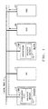
- FIG. 1 shows an illustrative multiprocessor system which is based on the AT&T 3B15 computer.
- the 3B15 system comprises a plurality of units, or stations, of which four stations 12, 13, 26, and 27 are shown.
- Various functions that need to be performed by the system are distributed among the stations.
- Each station of the system is dedicated to performing some function, which function is commonly different from the functions of the other stations, but the stations cooperate with each other in carrying out system tasks.
- a first station 12 functions as the principal processor and central controller of the system, performing data processing operations and coordinating system activities;
- a second station 13 functions as the main memory (MM) of the system, providing control of storage in, and retrieval from, memory of programs executing in processor 12 and of data required or produced by processor 12 during program execution;
- third and fourth stations 26 and 27 function as input and output controllers (IOC), controlling and coordinating the functions of various peripheral devices that provide the system with bulk storage or communications with the outside world.
- Other stations (not shown) with similar or different functional capabilities as the stations 12, 13, 26, and 27 may be included in the 3B15 system.
- the function of each station is dictated by its internal composition and, in the case of an intelligent station, by the programs executing on its processor. Stations may be added to or deleted from the system as required by the applications to which the system is being put.
- LB local bus
- Hardware of the 3B15 computer is expanded to a multiprocessor configuration by means of a second processor 25 being connected to local bus 11.
- a single-board processor is connected to a single expansion station slot of local bus 11 in the manner of any other station.
- a dual-board processor--one that is identical to the conventional 3B15 processor 12, for example--occupies two expansion station slots of local bus 11.
- an additional private processor communication bus must be connected between the two boards of processor 25, to provide connections equivalent to those conventionally provided by local bus 11 between the two station slots dedicated to processor 12. Irrespective of what board configuration is used to implement processor 25, all I/O peripheral interrupts are connected by local bus 11 only to master processor 12 and not to slave processor 25. This is indicated in FIG. 1 by the dashed line parallelling local bus 11.
- Processors 12 and 25 each illustratively comprise an AT&T WE 32100 microprocessor acting as the processor's central processing unit (CPU), two WE 32101 demand-paged memory management units (MMUs) and a WE 32106 math acceleration unit (MAU). These units are together labeled as 100. Though processors 12 and 25 share use of memory 13, each has on-board dedicated, or private, memory, labeled 101. I/O units 26-27 include a disk in support of demand-paged memory 13.
- Processors 12 and 25 run under control of a demand-paged version of the UNIX operating system of AT&T.
- the operating system is substantially the conventional, uniprocessor version, modified as described below.
- the 3B15 system uses two modes, or levels, of operation of the WE 32100 microprocessor: a user mode for executing user program instructions, and a privileged mode for executing functions such as operating system instructions that have the potential for corrupting shared system resources such as hardware resources.
- a process switch mechanism for entering privileged mode from user mode
- a system call mechanism for entering privileged mode from user mode
- the system call mechanism is also known by names such as a supervisory call and an operating system trap.
- the system call effectively acts as a subroutine call. It provides a means of controlled entry into a function by installing on a processor a new processor status word (PSW) and program counter (PC).
- PSW processor status word
- PC program counter
- the system call mechanism is used by explicit operating system GATE calls to transfer control from user to privileged mode, and is also used to handle "normal" system exceptions. ("Quick" interrupts, which would also be handled by this mechanism, are not used by the UNIX operating system or similar environments, and hence are ignored in this discussion.)
- An exception is an error condition--a fault or a trap--other than an interrupt. Normal exceptions constitute most system exceptions.
- the normal exception handlers are privileged-mode functions.
- the system call mechanism uses the execution stack of the present process; that is, a normal exception handler or a function called via a GATE instruction uses for its execution the execution stack of the process that was executing when the exception or the GATE call occurred.
- Each execution stack has upper and lower bounds, which are maintained in the process control block (PCB) of the process that is using the stack.
- a typical process control block 200 is shown in FIG. 2.
- the process control block is a data structure in memory 13 that contains the hardware context of the process when the process is not running. This context consists of the initial and intermediate (present) contents 211 and 212 of the processor status word (a register that contains status information about the microprocessor and the presently-executing process), the initial and intermediate contents 213 and 214 of the program counter, the initial and intermediate contents 215 and 216 of the execution stack pointer (SP), the lower bound value 217 and the upper bound value 218 for the execution stack, and other information 219 such as the last contents of general purpose registers, frame and argument pointers, and block move specifications.
- the processor status word a register that contains status information about the microprocessor and the presently-executing process
- SP execution stack pointer
- the lower bound value 217 and the upper bound value 218 for the execution stack
- other information 219 such
- PCBP Process control block pointer
- SP stack pointer
- the check is entered at step 300, and the present value of stack pointer 203 is compared with the contents of PCB location offset from PCBP 202 by 12, which is stack lower bound 217, at step 302. If the stack pointer value exceeds the lower bound, the present value of stack pointer 203 plus eight is compared with the contents of PCB location offset from PCBP 202 by 16 (decimal), which is stack upper bound 218, at step 304.
- the transfer occurs only if the stack pointer value falls within the specified bounds, at step 306; if the stack pointer does not fall within the specified bounds, a stack exception is generated, at step 308.
- the microprocessor performs the check automatically, either directly in hardware or by execution of a micro-instruction, i.e., firmware, sequence.
- the processor handles the normal exception or GATE request within the process in which it occurred: the processor status word and the program counter of the process that was executing when the system call mechanism was activated are stored on that process' execution stack, the stack pointer is incremented, and the program counter and processor status word of the called function are loaded into the program counter and processor status word registers.
- These activities are likewise performed automatically, either by hardware or by execution of a micro-instruction sequence.
- GATE calls and normal exceptions have their own separate micro-instruction sequences.
- the process switch mechanism is used by interrupts and "non-normal" exceptions including the stack exception.
- the process switch mechanism uses a different execution stack for the old and the new processes.
- the stack exception handler process has its own execution stack different from the execution stack of the excepted-to process.
- the interrupt handler process has its own execution stack different from the execution stack of the interrupted process. Because a different execution stack is used for each interrupt handler and non-normal exception handler, the execution stack bounds check is not performed upon the occurrence of an interrupt or a non-normal exception.
- the microprocessor On leaving a process during an interrupt or a stack exception process switch, the microprocessor saves that process' process control block pointer on a system-wide interrupt stack, and then writes the process' hardware context--the present program counter, stack pointer, and processor status word values, as well as the contents of other registers commonly stored in the process control block--in that process' process control block (pointed to by the present value of the process control block pointer). To enter a new process, the microprocessor obtains the process control block pointer of the new process and uses it to access the process control block of the new process and to load therefrom the new process' hardware context into the hardware registers.
- the above-described activities are performed automatically by the microprocessor, either directly in hardware or by execution of a micro-instruction sequence.
- the interrupts and each of the non-normal exceptions have their own separate micro-instruction sequence.
- the micro-instruction sequences of the system call and process switch mechanisms locate the processor status word and program counter of a new function, or the process control block pointer of a new process, in vector tables provided by the operating system.
- the operating system For normal exceptions and GATE calls, the operating system provides a pointer table which contains starting addresses for a set of handling-routine tables, and the handling-routine tables themselves. Each handling-routine table contains the processor status word and program counter values for a group of functions.
- the operating system provides an exception-vector table which contains the process control block pointers of the non-normal exception handler processes.
- the operating system provides an interrupt vector table which stores the initial process control block pointers of interrupt handler processes.
- An illustrative vector table 201 is shown in FIG. 2.
- processors 12 and 25 operate in a master-slave configuration.
- slave processor 25 performs substantially only user-mode processing, that is, processing that does not make use of operating system (privileged) services
- master processor 12 performs substantially all processing that involves operating system services, in addition to performing user-mode processing. Any process executing on slave processor 25 that requires operating system services for its continued execution is transferred for execution to master processor 12.
- a process executing on slave processor 25 is allowed to execute thereon until execution of an instruction thereof results in an invocation of an operating system service, or until detection of some asynchronous event requiring performance of operating system services for the process.
- An example of the latter is the expiration of an alarm clock timer.
- execution of the process on slave processor 25 is suspended.
- Execution of the instruction that resulted in the invocation of the operating system service is not completed on slave processor 25.
- the process is transferred to master processor 12. Execution on master processor 12 of the transferred process is resumed with the interrupted instruction.
- the execution of the interrupted instruction is either restarted on master processor 12, or execution of the partially-executed instruction is merely completed on master processor 12. Unless the condition that caused the attempt to enter privileged mode was a transient fault, execution of that instruction on master processor 12 results in the invocation of the operating system service. That service is then provided in a conventional, uniprocessor, manner on master processor 12. Illustratively, execution of the transferred process then continues on master processor 12.
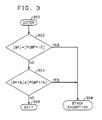
- the automatic invocation is basically accomplished as shown in FIG. 4 .
- Execution stack bounds 217, 218 stored in process control block 200 of a process are given an improper value, at step 450, before the process is executed on slave processor 25.
- This ensures failure, at step 454, of the stack bounds check performed, at step 453, during an attempt to enter privileged execution mode, at step 452, via a GATE call or occurrence of a normal exception.
- the failure of the check results in invocation of the stack exception handler process, at step 455.
- interrupt and exception process control blocks are set up for slave processor 25 in its private memory 101, and values therein for handlers of interrupts and non-normal exceptions that may occur on slave processor 25 are redirected, at step 456, to the value of an error-handler process that is a duplicate of the stack exception handler process for purposes of this application.
- private on-board memory is to duplicate virtual-to-physical translation tables, one for each processor, and replace appropriate entries therein so as to provide each processor with different, exclusive, virtual-to-physical translations for certain ranges of virtual addresses.
- the stack exception and error handler processes of the slave processor 25 are communication processes that restore, at step 459, to a proper value the stack bounds of the user process that was executing on slave processor 25 at the time the handler process was invoked, and transfer that user process for execution from slave processor 25 to master processor 12, at step 460.
- privileged execution mode would have been entered on slave processor 25, at step 461, and program execution would have continued in that mode, at step 462, as is done on master processor 12.
- a conventional handler would have been invoked at step 458 that would have processed the interrupt or condition, at step 463, as is done on master processor 12.
- master processor 12 executes a slave initialization routine flowcharted in FIG. 5.
- master processor 12 checks whether the system is a uniprocessor or a multiprocessor system, that is, whether processor 25 is present in the system of FIG. 1, at step 401.
- Processor 12 makes the determination by examining contents of a conventional firmware device table.
- the search for slave processor 25 is performed by scanning the equipped device table looking for a processor board located at an address other than the fixed address.
- processor 12 sets a UTILIZE variable in memory 13 to a zero value to indicate that there is no slave processor 25 in the system, and then returns to the master initialization routine to complete system initialization in the conventional uniprocessor manner, at step 405.
- step 401 the next step in the initialization is to set up separate process control blocks for exceptions and error conditions that can occur on both processors 12 and 25, at step 402. This is necessary because if the process control blocks are common to both processors 12 and 25, master processor 12 could be executing out of a process control block and have the slave processor 25 start trying to execute out of the same process control block, thus leading to register and stack corruption.
- process control block pointer value in main memory 13 is changed to point to a process control block located in the address range of private memory 101 of processors 12 and 25, thus giving common virtual addresses and physical addresses, yet different physical locations and values, to the master's and the slave's process control blocks.
- process control block pointers are used by both master and slave processors 12 and 25, and therefore the initialization of the private memory 101-resident process control blocks must be performed for all processors 12 and 25.
- the newly-placed process control blocks are initialized in private memory 101 of master processor 12, at step 402. Although only 5 fields in the process control block require initialization (initial program counter, initial program status word, initial stack pointer, stack lower bound, and stack upper bound), the initialization is done by copying over the entire contents of the "original" process control block, to simplify the code.
- slave processor 25 still has not been activated.
- Memory management information for the slave is also prepared at step 403. Since the kernel mapping is common for all processors, the MMU register contents will be common for all operating system kernel sections. However, access to MMUs on slave processor 25 is not possible from master processor 12 (and vice versa), and therefore the actual initialization of the MMU mapping register contents must be performed by slave processor 25.
- One technique for accomplishing this is to make use of the block-move capability of the microprocessor. This involves initializing a series of block move areas in the initial slave process control block such that when a process switch to the slave's initial process control block is performed, the MMU mapping registers will be automatically initialized as part of the XSWITCH_THREE() macro-ROM sequence of the microprocessor (see the WE 32100 Microprocessor Information Manual).
- slave's initial process control block has been setup, various control parameters related to slave support are initialized, at step 403.
- the physical address of the slave physical startup routine (see steps 501 and 502 of FIG. 5) is placed in a location in private memory 101 of slave processor 25 that is being polled by the slave's firmware, at step 404, to signal slave processor 25 to start executing the slave physical startup routine.
- Processor 12 then returns to the master initialization routine to complete system initialization in the conventional uniprocessor manner, at step 405.
- the firmware of master processor 12 and slave processor 25 is identical. Upon power-up, the firmware checks whether the processor is the master or the slave. Illustratively, this check is performed by examining the address of the bus 11 slot to which the processor is connected. If the processor is the master, it commences executing at a predetermined memory address, in the conventional manner. If the processor is a slave, after initialization it begins to poll a predetermined location.
- slave processor 25 The initial slave process executed by slave processor 25 is flowcharted in FIG. 6. Once slave processor 25 firmware that is polling the above-mentioned location sees this location set to a non-zero value, at step 500, control is transferred to the physical address indicated by that value. This commences execution of the physical startup routine for slave processor 25. This is the first code to execute on slave processor 25. The purpose of this code is to complete slave processor 25 hardware initialization.
- the first step is to flush the slave processor 25 instruction cache, at step 501, since its contents are unpredictable.
- the slave's interrupt stack pointer register is initialized to point to the second word in the interrupt stack, at step 502. (The first word in the interrupt stack was initialized to be the physical address of the slave's initial process control block).
- a process switch to the slave's initial process control block is performed by the conventional RETPS instruction.
- the slave's process control block pointer register is set to the physical address of the intermediate portion of the slave's initial process control block
- the initial program counter is set to the physical address of the code to enable virtual mode addressing
- register r0 is set to contain the virtual address of the slave's virtual-mode startup routine (step 504)
- the slave's MMU mapping registers are set to the same values as the master's MMU mapping registers (thus presenting a common master/slave mapping)
- the other initial register values are setup for slave processor 25, as prepared by the slave initialization routine of FIG. 5.
- slave processor 25 enbvjmp code, at step 503, which resets the process control block pointer register to the virtual address of the intermediate portion of the slave's initial process control block, and executes the conventional ENBVJMP instruction which enables virtual addressing for slave processor 25 and transfers to the virtual address contained in register r0.
- the slave virtual-mode startup routine is represented by step 504. It is responsible for final initialization of slave processor 25 and for passing a synchronization message back to master processor 12 to indicate that initialization has completed.
- This final initialization includes slave processor 25 hardware initializations to set the cacheable bit in the slave MMU configuration registers, flush and enable the system cache associated with slave processor 25, disable all slave processor 25 hardware timers (they are never enabled, as there is no need for software support for slave timer interrupts), perform standard slave processor 25 MAU initialization via the standard mauinit() routine, initialize the interrupt controller, and enable interrupts on slave processor 25 (the initial slave program status word has all interrupts masked, so even though interrupts are enabled by the hardware circuitry, they are still masked for now).
- the process control blocks resident in private memory 101 of slave processor 25 are also initialized with respect to the slave handlers associated with these process control blocks, at step 504. This involves redefining initial values and stack bounds for the slave stack exception handler and slave system error exception handler, as the handling of these exception conditions is different for slave processor 25 from the conventional handling done for master processor 12.
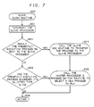
- FIG. 7 flowcharts the slave clock routine which is called as part of the clock interrupt-handling routine of master processor 12.
- slave processor 25 supports timer interrupts in exactly the same manner as master processor 12, in this illustrative embodiment there is no need for software support for timer interrupts on the slave. Instead, whenever a timer interrupt occurs on the master, a check is made of the UTILIZE flag, and if it is set (indicating presence of a slave processor 25), the routine of FIG. 7 is called, at step 600.
- This routine performs three basic functions: interrupts slave processor 25, at step 601; determines if the process presently executing on master processor 12 is eligible for execution on slave processor 25, at step 602; and if not, determines if a process switch should occur due to time-slice expiration for the process presently executing on master processor 12, at step 603.
- the determination of slave processor 25 execution worthiness at step 602 is based on whether a process can execute on slave processor 25.
- a process can execute on slave processor 25 only if it was in user-mode at the time of the clock interrupt and only if the process is not presently being profiled, i.e., conventionally monitored by the system for information-gathering purposes. If at step 602 a process is deemed capable of execution on slave processor 25, a SONSLAVE bit in the conventional processor p_flag field is set to so indicate, at step 604, and the standard runrun flag is set, at step 605.
- the former posts a request to a slave add routine (see FIG. 8) to transfer the process to slave processor 25, and the latter posts a request to the conventional pswtch() routine for a process switch that is acted upon before the clock interrupt handler returns to the interrupted program, at step 606.
- Time-slicing is implemented at step 603 by associating with each process a counter that is incremented every clock tick, and once the counter is found to exceed a system threshold, a process switch request is posted via the runrun flag, at step 605.
- the process switch request is made only if there are runnable processes in the system that are blocked.
- the counter is reset every process switch.
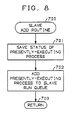
- FIG. 8 flowcharts the slave add routine which executes on master processor 12 and may be called at step 700 by an interrupt handler routine of either processor to add the process presently executing on master processor 12 to the run queue of slave processor 25.
- the slave add routine is similar to the standard setrq() routine for the master processor 12 run queue: in fact, the setrq() routine has a check in it to see if the process should be transferred to the slave processor 25 run queue (SONSLAVE flag in the p_flag field), and if so, calls the slave add routine to perform the transfer.
- Transferring a process to the slave processor 25 run queue involves saving the MAU status of the presently-executing process (equivalent to the standard mau_save()routine), at step 701, and actually adding the process to the slave processor 25 run queue, at step 702, before returning at step 703. If slave processor 25 is idle, it may be interrupted to ensure immediate execution of the newly-added process.
- FIGS. 9 and 10 flowchart the slave processor system interrupt handler routine, or slave interrupt routine for short, which executes on slave processor 25.
- slave processor 25 There are only two reasons in this example for slave processor 25 to be interrupted: either a clock interrupt occurred on master processor 12, or a process was transferred from master processor 12 to slave processor 25 run queue while slave processor 25 was idle.
- the two types of interrupts are distinguishable by checking, at step 801, if the conventional time counter lbolt of master processor 12 has changed since the last time the slave interrupt routine was invoked: if it has changed, then a time interval has elapsed since the last interrupt and the present interrupt is due to this passing of time; if no change has occurred, the present interrupt is due to the addition of a process to slave processor 25 run queue while slave processor 25 was idle.
- the first action performed is a check of a flag variable, at step 802, to see if master processor 12 is trying to reclaim memory. If so, the execution of processes on slave processor 25 is suspended until the reclamation has completed. This is necessary since there exists a potential corruption problem if the reclamation processing modifies a page descriptor that is resident in the slave processor 25 MMU descriptor caches: there is no technique for informing slave processor 25 of the change in the descriptor, and therefore slave processor 25 will be using obsolete mapping information.
- stack bounds 217, 218 of the process that is presently executing on slave processor 25 are restored to their correct value (see step 1302 of FIG.
- a process switch is forced on slave processor 25 by calling a slave process switch routine (see FIG. 11), at step 804.
- the slave process switch routine ensures that MMU mapping registers are loaded with new information, which also has the beneficial effect of flushing the potentially-corrupt MMU cache descriptor entries.
- time-related information maintained for the interrupted process is adjusted, at step 805.
- the elapsed time since the last invocation of the slave interrupt routine is calculated, and the present lbolt value is saved. If slave processor 25 is idle, i.e., slave processor 25 was not executing a process at the time the slave interrupt routine was called, the elapsed time is accounted for as system idle time in the same manner as master processor 12 idle time (i.e. sysinfo.cpu[CPU_IDLE] is incremented by the amount of elapsed time). Otherwise, the timers and timing accumulators related to an executing process are incremented by the amount of elapsed time.
- step 806 a check like that of step 802 is made, at step 806, to determine if master processor 12 is trying to reclaim memory, and if so, the execution of processes on slave processor 25 is suspended until reclamation has completed. At this point, a check is made for whether the presently-executing process has had an asynchronous signal posted for it while it was executing on slave processor 25, at step 807. If so, the process is sent back to master processor 12 and a process switch is performed on slave processor 25, by invocation of a slave delete routine (see FIG. 15), at step 808.
- master processor 12 was not reclaiming as determined at step 806, if there are no signals pending for the present process as determined at step 807, and if the present process has not exceeded its time slice as determined at step 809, control is transferred directly back to the process that was executing on slave processor 25 at the time of the interrupt, at step 814.
- FIG. 11 flowcharts the slave process switch routine, which executes on slave processor 25. It is responsible for selecting the next process to execute on slave processor 25, as well as initialization of slave processor 25 for the new process. It is equivalent to the standard pswtch() routine of master processor 12.
- slave processor 25 in control.
- the context of slave processor 25 is setup for the new process, at step 907, by loading the MMU mapping registers and also MAU registers (if necessary), clearing MMU fault indications, and resetting the time slice counter for the process (p_slice). Execution is then transferred to the new process, at step 908.
- FIG. 12 flowcharts the slave stock exception handler process.
- minimal privileged-mode processing is implemented on slave processor 25 (no privileged mode processing is done on slave processor 25 on behalf of user processes)
- the action performed by the slave stack exception handler is to transfer the presently-executing user process to master processor 12.
- This is implemented by calling a slave delete routine (see FIG. 15) , at step 1002.
- the faulting instruction is reexecuted once the process restarts execution on master processor 12. This feature is fairly typical of systems with demand-paged memory management. This results in repeating whatever actions caused the original fault on slave processor 25, therefore avoiding the need for the slave stack exception handler to preserve potential fault indicators and the master exception handling routines to look for the saved potential fault indicators.
- system error Although far less usual than normal exceptions, another exception condition is possible when executing user-mode processes: system error. This category includes things like alignment faults and hardware problems encountered as a result of actions performed by slave processor 25. In these situations, the slave system error handler process flowcharted in FIG. 13 is invoked, at step 1100. It behaves exactly the same as the slave stack exception handler process of FIG. 12: the user process PCB is setup, at step 1101, so that execution on master processor 12 will commence with the instruction restart routine, and the process is then transferred to master processor 12 through invocation of the slave delete routine, at step 1102.
- the instruction restart routine is flowcharted in FIG. 14. This routine is invoked, at step 1200, on master processor 12 whenever a process that was transferred from slave processor 25 due to occurrence of an exception or an interrupt begins to execute on master processor 12.
- the routine checks whether the faulting instruction is a non-restartable instruction, at step 1201, such as an MAU instruction with destructive operand overlap, and if so, it corrects the restart problems, at step 1202.
- the routine uses existing routines to handle restartability problems in the same manner as the standard, master, stack exception handler deals with MAU restart problems.
- the instruction restart routine restores the address of the user process' faulted instruction to the process control block of the faulted process to cause execution of the faulted instruction, at step 1203, and returns at step 1204 to execution of that instruction.
- FIG. 15 flowcharts the slave delete routine.
- This routine is invoked on slave processor 25 whenever it is deemed necessary to transfer a process presently executing on slave processor 25 to the master processor 12 run queue.
- this situation can be the result of either an asynchronous signal having been posted for a presently-executing process (see step 808 of FIG. 9), or the presently-executing slave process having need of privileged-mode processing (see step 1002 of FIG. 12 and step 1102 of FIG. 2).
- the actions performed are the same: preserve present status of the process, add the present process to master processor 12 run queue, and select a new process for execution on slave processor 25.
- Preserving the status for the present process is essentially completed by the time the slave delete routine is called: all paths leading to invocation of the slave delete routine result in the saving of the required CPU-related registers in the process control block for the presently-executing slave process.
- the process control block only defines the hardware context of a process, but does not define the software-maintained information for the process, such as MAU register contents.
- the software-defined state must be saved in the process' PCB, at step 1301.
- the SONSLAVE flag is reset in the p_flag field. This leaves only restoration of the actual value of stack upper bound 218 to be performed, at step 1302.
- the process is added to master processor 12 run queue through invocation of the standard setrq() routine, at step 1303, and a new process is chosen for execution on slave processor 25 through invocation of the slave process switch routine of FIG. 11 , at step 1304.
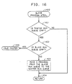
- FIG. 16 flowcharts the slave process steal routine, which is invoked on master processor 12 at the start of the pswtch() routine.
- the pswtch() routine calls the slave process steal routine, at step 1400, to avoid situations where master processor 12 run queue is empty and master processor 12 sits idle, at step 1401, and there exists a backlog of user-mode processes on slave processor 25 run queue, at step 1402.
- This routine simply takes a process off of slave processor 25 run queue, following the same process selection algorithm as the slave process switch routine of FIG. 11, and moves the process to master processor 12 run queue, at step 1403.
- step 1403 the routine returns to the pswtch() routine, at step 1404, to select a process from master processor 12 run queue for execution on master processor 12. If the master processor 12 run queue is found to be empty, at step 1401, and the slave processor 25 run queue is also found to be empty, at step 1402, the routine idles master processor 12, at step 1405, by execution of a standard WAIT instruction. Master processor 12 then waits for occurrence of an interrupt.
- FIG. 17 flowcharts the slave idle routine, which is invoked, at step 1500, on slave processor 25 if no processes are available for execution on slave processor 25.
- This routine resets slave processor 25 interrupt stack pointer, at step 1501, lowers the interrupt priority level (set high by hardware operations preceding invocation of the slave stack exception handler) in the program status word to the lowest level to allow all interrupts, at step 1502, and executes a WAIT instruction, at step 1503.
- execution on slave processor 25 is resumed at the slave interrupt routine of FIGS. 9 and 10.
- the AT&T 3B2 uniprocessor computer and other uniprocessor computers may be expanded to a multiprocessor configuration in like manner.
- more than one slave processor may be added to and used in the system, in substantially the same manner as the one slave processor is added and used.
- slave processors need not be identical to each other or to the master processor, but each may be based on a different microprocessor architecture.
Landscapes
- Engineering & Computer Science (AREA)
- Software Systems (AREA)
- Theoretical Computer Science (AREA)
- Physics & Mathematics (AREA)
- General Engineering & Computer Science (AREA)
- General Physics & Mathematics (AREA)
- Hardware Redundancy (AREA)
- Multi Processors (AREA)
Abstract
Description
- The invention relates to a multiprocessor system generally, and in particular to the manner in which functions are distributed and control is transferred between processors in a multiprocessor system.
- In comparison with uniprocessor computer systems, multiprocessor computer systems are typically complex in design, in terms of both hardware and software. For example, multiprocessor systems typically require special and complex inter-processor communication mechanisms and protocols, special arrangements for access by a plurality of processors to shared input and output resources, and memory and other resource locking arrangements to avoid race conditions and simultaneous-access conflicts between processors.
- Many of these complexities may be avoided by means of a master-slave multiprocessor configuration, wherein one or more slave processors perform only user-instruction processing and transfer processes for operating system service processing to a master processor. With respect to I/O devices and other periphery, such a system appears as, and hence may be interacted with as, a uniprocessor consisting of the master processor. Many operating system complexities involving shared-resource locking, race condition avoidance, and other inter-processor cooperation matters are avoided thereby.
- Nevertheless, many complexities still remain in such a multiprocessor design, especially in the operating system software, because of the need for the plurality of processors to communicate and transfer control from one to another. For example, DE-A-3,105,527 discloses a multiprocessor system wherein one processor is used to execute operating system functions and a second processor executes user functions. Every operating system function call by the second processor is communicated to the first processor; the first processor executes the call while the caller either continues execution on the second processor or halts to await the result of the call; and results of the call execution are communicated from the first processor back to the caller on the second processor. Consequently, it is a problem in the art that a uniprocessor is typically not "growable" into a multiprocessor, and that a uniprocessor may be converted into a multiprocessor only through extensive operating system redesign, and that changes required to be made to convert a uniprocessor system design into a multiprocessor system design are not transparent to application programs.
- This invention is directed to solving the problems of the prior art. Illustratively according to the invention as claimed, a multiprocessor system is operated in the following manner: occurrence of any event of a plurality of predetermined events--for example, interrupts or other events leading to invocation of operating system services--on a first--a slave--processor is detected, and an indicator associated with the occurred event is examined to determine what function is to be performed in response. The indicated function is then performed, whereby a process that was executing on the first processor is transferred to a second--the master--processor, for execution.
- Consequently, occurrence of an event, such as would lead to invocation of operating system services on the first processor, leads to transfer of the process that caused the invocation to the second processor, where, advantageously, the desired service may be provided. The transferred process is illustratively the one during whose execution the event was detected. Provisioning of the service on the second processor is accomplished as follows: another indicator associated with the occurred event is examined to determine what function is to be performed in response on the second processor. Illustratively, re-occurrence of the event during execution of the transferred process on the second, master, processor, causes examination of the other indicator to be made. But this time the identified function is one whose performance handles the occurred event and illustratively provides the called-for service.
- According to the invention, then, a multiprocessor system that includes the first and the second processor also includes a first function which, when performed, results in transfer of a process executing in the first processor at occurrence of any of the predetermined events to the second processor for execution, a first indicator identifying the first function as the function to be performed in response to occurrence of any of the events on the first processor, and an arrangement for performing the function identified by the first indicator when any of the events occurs on the first processor. By this configuration the inter-processor transfer of the process is accomplished.
- Illustratively to provide the called-for operating system service on the second processor, the multiprocessor further includes a second function which, when performed, processes the event, a second indicator identifying the second function as the function to be performed on the second processor in response to occurrence of an event, and an arrangement for performing the function identified by the second indicator when the transferred process commences execution on the second processor.
- According to an illustrative embodiment of the invention, the first and second indicators are each one of a plurality of first and second indicators, respectively. The indicators of each plurality are each associated with a different one of the events and each identifies a function to be performed in response to occurrence of the associated event, on the first processor in the case of the first indicators and on the second processor in the case of the second indicators. Illustratively, these indicators are interrupt vectors. The first indicators all identify the first function whereas the second indicators each identify potentially a different one of a plurality of second functions. Each second function when performed processes the associated event.
- The advantage of operating a multiprocessor system in the master-slave configuration is the resultant simplicity of the operating system: complexities associated with memory locking mechanisms and race condition resolution are significantly reduced, and complexities associated with user and input and output (I/O) interfaces are thereby avoided. The above-summarized manner of configuring and operating a multiprocessor system of the master-slave type yields further simplifications of the operating system, and also of the multiprocessor hardware. Advantageously, a multiprocessor can now be constructed from a uniprocessor merely by adding a conventional processor's hardware to a conventional uniprocessor system (for example, by simply connecting the new processor's hardware to a slot of the uniprocessor's communication bus), and by making minimal changes to the uniprocessor system's operating system software. Advantageously, changes that would conventionally be required to be made to the multitudes of routines through which operating system services may be invoked on a slave processor are avoided. The minimal changes that remain allow the multiprocessor operating system software to run on the uniprocessor effectively with no degradation in performance, so that a uniprocessor system may be constructed whose later, e.g. field, upgrade to a multiprocessor requires no changes to the operating system software.
- Advantageously as a result of the invention, the required changes to the uniprocessor operating system to convert it into a multiprocessor system are of such a nature that user and I/O interfaces are preserved intact, thus providing both source code and binary code compatibility with existing applications. From a customer's, a user's, or a developer's view, the conversion to multiprocessing introduces no incompatibilities or intricacies to the operating system. Additionally, all functionality provided by the multiprocessor system is available to all applications regardless of which processor they are presently executing on; only a single virtual machine image is presented to all processes. Uniprocessor system performance may thus be improved by system growth into a multiprocessor system without having to recode, recompile, redesign, redistribute, reformat, relink, remake, restructure, or replace existing applications.
- These and other advantages and features of the present invention will become apparent from the following description of an illustrative embodiment of the invention taken together with the drawing.
-
- FIG. 1 is a block diagram of a computer system embodying an illustrative implementation of the invention;
- FIG. 2 is a block diagram of a process control block and pointers of the system of FIG. 1;
- FIG. 3 is a flow diagram of a system call micro-sequence routine of the system of FIG. 1; and
- FIG. 4 is a flow diagram summarizing the steps involved in ensuring transfer of processes for privileged mode execution from the slave to the master processor of FIG. 1; and
- FIGS. 5- 17 are flow diagrams of various operating system routines of the system of FIG. 1.
- FIG. 1 shows an illustrative multiprocessor system which is based on the AT&T 3B15 computer. The 3B15 system comprises a plurality of units, or stations, of which four
stations first station 12 functions as the principal processor and central controller of the system, performing data processing operations and coordinating system activities; asecond station 13 functions as the main memory (MM) of the system, providing control of storage in, and retrieval from, memory of programs executing inprocessor 12 and of data required or produced byprocessor 12 during program execution; and third andfourth stations stations - For the purpose of cooperating with each other in carrying out system tasks, the stations of the system are interconnected by a local bus (LB) 11, which serves as the communication medium for the stations and allows any station within the system to communicate with any other station.
- Hardware of the 3B15 computer is expanded to a multiprocessor configuration by means of a
second processor 25 being connected to local bus 11. A single-board processor is connected to a single expansion station slot of local bus 11 in the manner of any other station. However, a dual-board processor--one that is identical to the conventional 3B15processor 12, for example--occupies two expansion station slots of local bus 11. In this latter arrangement, an additional private processor communication bus must be connected between the two boards ofprocessor 25, to provide connections equivalent to those conventionally provided by local bus 11 between the two station slots dedicated toprocessor 12. Irrespective of what board configuration is used to implementprocessor 25, all I/O peripheral interrupts are connected by local bus 11 only to masterprocessor 12 and not to slaveprocessor 25. This is indicated in FIG. 1 by the dashed line parallelling local bus 11. -
Processors processors memory 13, each has on-board dedicated, or private, memory, labeled 101. I/O units 26-27 include a disk in support of demand-paged memory 13. -
Processors - To make clear the purpose and effect of the modifications, a brief overview of the conventional operation of the uniprocessor and of the desired operation of the multiprocessor is in order. A full description of the WE 32100 microprocessor may be found in "UNIX™ Microsystem WE 32100 Microprocessor Information Manual" published by Document Development Organization-Microelectronics Projects Group, AT&T Technologies, Inc., Morristown, New Jersey. Hence, a brief description is presented below only of certain aspects of the operation that are deemed necessary for a full appreciation of the illustrative embodiment of the invention.
- Typically, the 3B15 system uses two modes, or levels, of operation of the WE 32100 microprocessor: a user mode for executing user program instructions, and a privileged mode for executing functions such as operating system instructions that have the potential for corrupting shared system resources such as hardware resources. There are two mechanisms for entering privileged mode from user mode: a process switch mechanism and a system call mechanism. The system call mechanism is also known by names such as a supervisory call and an operating system trap.
- The system call effectively acts as a subroutine call. It provides a means of controlled entry into a function by installing on a processor a new processor status word (PSW) and program counter (PC). The system call mechanism is used by explicit operating system GATE calls to transfer control from user to privileged mode, and is also used to handle "normal" system exceptions. ("Quick" interrupts, which would also be handled by this mechanism, are not used by the UNIX operating system or similar environments, and hence are ignored in this discussion.) An exception is an error condition--a fault or a trap--other than an interrupt. Normal exceptions constitute most system exceptions. The normal exception handlers are privileged-mode functions.
- The system call mechanism uses the execution stack of the present process; that is, a normal exception handler or a function called via a GATE instruction uses for its execution the execution stack of the process that was executing when the exception or the GATE call occurred.
- Each execution stack has upper and lower bounds, which are maintained in the process control block (PCB) of the process that is using the stack. A typical process control block 200 is shown in FIG. 2. The process control block is a data structure in
memory 13 that contains the hardware context of the process when the process is not running. This context consists of the initial and intermediate (present)contents intermediate contents intermediate contents bound value 217 and the upper boundvalue 218 for the execution stack, andother information 219 such as the last contents of general purpose registers, frame and argument pointers, and block move specifications. - In a transition from non-privileged state to privileged state, the system must always perform checks to ensure that the privileged state will not become corrupted. Therefore, prior to making a legal entry of a privileged function, i.e., before executing a transfer to the privileged mode upon the occurrence of a normal exception or a GATE request, the system call mechanism checks the present execution stack pointer value against the execution stack boundary values that are stored in the process control block of the presently-executing process, in the manner shown in FIG. 3. Process control block pointer (PCBP) 202 and stack pointer (SP) 203 are special registers of the microprocessor. The present value of
PCBP 202 points to an intermediate value of the presently-executing process' PCB 200 (see FIG. 2). The check is entered atstep 300, and the present value ofstack pointer 203 is compared with the contents of PCB location offset fromPCBP 202 by 12, which is stack lower bound 217, atstep 302. If the stack pointer value exceeds the lower bound, the present value ofstack pointer 203 plus eight is compared with the contents of PCB location offset fromPCBP 202 by 16 (decimal), which is stack upper bound 218, atstep 304. The transfer occurs only if the stack pointer value falls within the specified bounds, atstep 306; if the stack pointer does not fall within the specified bounds, a stack exception is generated, atstep 308. The microprocessor performs the check automatically, either directly in hardware or by execution of a micro-instruction, i.e., firmware, sequence. - If the stack pointer is found to fall within the specified bounds upon the occurrence of a GATE call or a normal exception, the processor handles the normal exception or GATE request within the process in which it occurred: the processor status word and the program counter of the process that was executing when the system call mechanism was activated are stored on that process' execution stack, the stack pointer is incremented, and the program counter and processor status word of the called function are loaded into the program counter and processor status word registers. These activities are likewise performed automatically, either by hardware or by execution of a micro-instruction sequence. Illustratively, GATE calls and normal exceptions have their own separate micro-instruction sequences.
- The process switch mechanism is used by interrupts and "non-normal" exceptions including the stack exception. The process switch mechanism uses a different execution stack for the old and the new processes. Thus, for example, the stack exception handler process has its own execution stack different from the execution stack of the excepted-to process. Similarly, the interrupt handler process has its own execution stack different from the execution stack of the interrupted process. Because a different execution stack is used for each interrupt handler and non-normal exception handler, the execution stack bounds check is not performed upon the occurrence of an interrupt or a non-normal exception.
- On leaving a process during an interrupt or a stack exception process switch, the microprocessor saves that process' process control block pointer on a system-wide interrupt stack, and then writes the process' hardware context--the present program counter, stack pointer, and processor status word values, as well as the contents of other registers commonly stored in the process control block--in that process' process control block (pointed to by the present value of the process control block pointer). To enter a new process, the microprocessor obtains the process control block pointer of the new process and uses it to access the process control block of the new process and to load therefrom the new process' hardware context into the hardware registers.
- The above-described activities are performed automatically by the microprocessor, either directly in hardware or by execution of a micro-instruction sequence. Illustratively, the interrupts and each of the non-normal exceptions have their own separate micro-instruction sequence.
- The micro-instruction sequences of the system call and process switch mechanisms locate the processor status word and program counter of a new function, or the process control block pointer of a new process, in vector tables provided by the operating system. For normal exceptions and GATE calls, the operating system provides a pointer table which contains starting addresses for a set of handling-routine tables, and the handling-routine tables themselves. Each handling-routine table contains the processor status word and program counter values for a group of functions. For non-normal exceptions, the operating system provides an exception-vector table which contains the process control block pointers of the non-normal exception handler processes. And for interrupts, the operating system provides an interrupt vector table which stores the initial process control block pointers of interrupt handler processes. An illustrative vector table 201 is shown in FIG. 2.
- For purposes described in the Background portion of this document, it is desirable to have
processors slave processor 25 performs substantially only user-mode processing, that is, processing that does not make use of operating system (privileged) services, andmaster processor 12 performs substantially all processing that involves operating system services, in addition to performing user-mode processing. Any process executing onslave processor 25 that requires operating system services for its continued execution is transferred for execution tomaster processor 12. - To enable the inter-processor transfer to be made with minimal modifications of the operating system, a process executing on
slave processor 25 is allowed to execute thereon until execution of an instruction thereof results in an invocation of an operating system service, or until detection of some asynchronous event requiring performance of operating system services for the process. An example of the latter is the expiration of an alarm clock timer. At that point, execution of the process onslave processor 25 is suspended. Execution of the instruction that resulted in the invocation of the operating system service is not completed onslave processor 25. The process is transferred tomaster processor 12. Execution onmaster processor 12 of the transferred process is resumed with the interrupted instruction. Illustratively, the execution of the interrupted instruction is either restarted onmaster processor 12, or execution of the partially-executed instruction is merely completed onmaster processor 12. Unless the condition that caused the attempt to enter privileged mode was a transient fault, execution of that instruction onmaster processor 12 results in the invocation of the operating system service. That service is then provided in a conventional, uniprocessor, manner onmaster processor 12. Illustratively, execution of the transferred process then continues onmaster processor 12. - To enable the above-described transfer of a process from
slave processor 25 tomaster processor 12 to be made without having to extensively modify operating system functions or processes invokable onslave processor 25 such that invocation thereof would result in the invoking process being transferred tomaster processor 12, all attempts made onslave processor 25 of this illustrative system to enter privileged mode are either caused to encounter a predetermined condition which in turn results in invocation of a handler that is common to all those attempts, or are redirected to a common handler. The invoked handler then performs the above-described process transfer. The handler is invoked automatically onslave processor 25, either directly by hardware or by execution of a micro-instruction sequence. - The automatic invocation is basically accomplished as shown in FIG. 4 . Execution stack bounds 217, 218 stored in process control block 200 of a process are given an improper value, at
step 450, before the process is executed onslave processor 25. This ensures failure, atstep 454, of the stack bounds check performed, atstep 453, during an attempt to enter privileged execution mode, atstep 452, via a GATE call or occurrence of a normal exception. The failure of the check results in invocation of the stack exception handler process, atstep 455. Also, at system initialization, interrupt and exception process control blocks are set up forslave processor 25 in itsprivate memory 101, and values therein for handlers of interrupts and non-normal exceptions that may occur onslave processor 25 are redirected, atstep 456, to the value of an error-handler process that is a duplicate of the stack exception handler process for purposes of this application. (An alternative to using private on-board memory is to duplicate virtual-to-physical translation tables, one for each processor, and replace appropriate entries therein so as to provide each processor with different, exclusive, virtual-to-physical translations for certain ranges of virtual addresses.) Upon occurrence of an interrupt or non-normal exception onslave processor 25, atstep 457, these values cause invocation of the handler process, atstep 458. The stack exception and error handler processes of theslave processor 25 are communication processes that restore, atstep 459, to a proper value the stack bounds of the user process that was executing onslave processor 25 at the time the handler process was invoked, and transfer that user process for execution fromslave processor 25 tomaster processor 12, atstep 460. (Had the stack bounds check not failed atstep 454, privileged execution mode would have been entered onslave processor 25, atstep 461, and program execution would have continued in that mode, atstep 462, as is done onmaster processor 12. Similarly, had the vectors not been redirected atstep 456, a conventional handler would have been invoked atstep 458 that would have processed the interrupt or condition, atstep 463, as is done onmaster processor 12.) - Returning now to a consideration of the system of FIG. 1, uniprocessor system initialization is modified therein as shown in FIG. 4.
- As part of master initialization of all system hardware,
master processor 12 executes a slave initialization routine flowcharted in FIG. 5. After entering execution of the routine, atstep 400,master processor 12 checks whether the system is a uniprocessor or a multiprocessor system, that is, whetherprocessor 25 is present in the system of FIG. 1, atstep 401.Processor 12 makes the determination by examining contents of a conventional firmware device table. Illustratively, since the board identification forslave processor 25 is identical to that ofmaster processor 12 and the board address formaster processor 12 is fixed, the search forslave processor 25 is performed by scanning the equipped device table looking for a processor board located at an address other than the fixed address. - If no
slave processor 25 is found atstep 401,processor 12 sets a UTILIZE variable inmemory 13 to a zero value to indicate that there is noslave processor 25 in the system, and then returns to the master initialization routine to complete system initialization in the conventional uniprocessor manner, atstep 405. - If the system is found, at
step 401, to be equipped with aslave processor 25, the next step in the initialization is to set up separate process control blocks for exceptions and error conditions that can occur on bothprocessors step 402. This is necessary because if the process control blocks are common to bothprocessors master processor 12 could be executing out of a process control block and have theslave processor 25 start trying to execute out of the same process control block, thus leading to register and stack corruption. Therefore, separate process control blocks are setup for stack exceptions and system error exceptions, by changing the process control block pointer value inmain memory 13 to point to a process control block located in the address range ofprivate memory 101 ofprocessors slave processors processors - Next, the newly-placed process control blocks are initialized in
private memory 101 ofmaster processor 12, atstep 402. Although only 5 fields in the process control block require initialization (initial program counter, initial program status word, initial stack pointer, stack lower bound, and stack upper bound), the initialization is done by copying over the entire contents of the "original" process control block, to simplify the code. - Up to now, all modifications of private memory have been performed on
private memory 101 ofmaster processor 12 and must be replicated for the slave processor's private memory. This replication is done by copying a dpccram_t data structure, which contains all per-processor data elements and which is now resident inprivate memory 101 ofmaster processor 12, toprivate memory 101 ofslave processor 25, and then changing specific slave-related variables therein, atstep 402. Not all elements of the structure need to be changed, but only those pertaining to interrupts and exceptions that can occur onslave processor 25. - At this point,
slave processor 25 still has not been activated. To actually activateslave processor 25, it is first necessary to prepare a control block for an initial process (see FIG. 6) ofslave processor 25, atstep 403. This involves placing the physical address of the slave's initial process control block in the first entry in the slave's interrupt stack, and setting the initial program counter to the physical address of the slave routine to enable virtual addressing via the conventional ENBVJMP instruction (seestep 503 of FIG. 6), setting the initial program status word, initial virtual stack pointer, and initial virtual stack boundaries, as well as setting the initial value for register r0 to the virtual address of a slave virtual-mode startup routine (seestep 504 of FIG. 6). - Memory management information for the slave is also prepared at
step 403. Since the kernel mapping is common for all processors, the MMU register contents will be common for all operating system kernel sections. However, access to MMUs onslave processor 25 is not possible from master processor 12 (and vice versa), and therefore the actual initialization of the MMU mapping register contents must be performed byslave processor 25. One technique for accomplishing this is to make use of the block-move capability of the microprocessor. This involves initializing a series of block move areas in the initial slave process control block such that when a process switch to the slave's initial process control block is performed, the MMU mapping registers will be automatically initialized as part of the XSWITCH_THREE() macro-ROM sequence of the microprocessor (see the WE 32100 Microprocessor Information Manual). - Once the slave's initial process control block has been setup, various control parameters related to slave support are initialized, at
step 403. Finally, the physical address of the slave physical startup routine (seesteps private memory 101 ofslave processor 25 that is being polled by the slave's firmware, atstep 404, to signalslave processor 25 to start executing the slave physical startup routine.Processor 12 then returns to the master initialization routine to complete system initialization in the conventional uniprocessor manner, atstep 405. - The firmware of
master processor 12 andslave processor 25 is identical. Upon power-up, the firmware checks whether the processor is the master or the slave. Illustratively, this check is performed by examining the address of the bus 11 slot to which the processor is connected. If the processor is the master, it commences executing at a predetermined memory address, in the conventional manner. If the processor is a slave, after initialization it begins to poll a predetermined location. - The initial slave process executed by
slave processor 25 is flowcharted in FIG. 6. Onceslave processor 25 firmware that is polling the above-mentioned location sees this location set to a non-zero value, atstep 500, control is transferred to the physical address indicated by that value. This commences execution of the physical startup routine forslave processor 25. This is the first code to execute onslave processor 25. The purpose of this code is to completeslave processor 25 hardware initialization. - The first step is to flush the
slave processor 25 instruction cache, atstep 501, since its contents are unpredictable. Once this has been accomplished, via the conventional CFLUSH instruction, the slave's interrupt stack pointer register is initialized to point to the second word in the interrupt stack, atstep 502. (The first word in the interrupt stack was initialized to be the physical address of the slave's initial process control block). Also atstep 502, a process switch to the slave's initial process control block is performed by the conventional RETPS instruction. As part of this process switch, the slave's process control block pointer register is set to the physical address of the intermediate portion of the slave's initial process control block, the initial program counter is set to the physical address of the code to enable virtual mode addressing, register r0 is set to contain the virtual address of the slave's virtual-mode startup routine (step 504), the slave's MMU mapping registers are set to the same values as the master's MMU mapping registers (thus presenting a common master/slave mapping), and the other initial register values are setup forslave processor 25, as prepared by the slave initialization routine of FIG. 5. - Now execution continues at the
slave processor 25 enbvjmp code, atstep 503, which resets the process control block pointer register to the virtual address of the intermediate portion of the slave's initial process control block, and executes the conventional ENBVJMP instruction which enables virtual addressing forslave processor 25 and transfers to the virtual address contained in register r0. - The slave virtual-mode startup routine is represented by
step 504. It is responsible for final initialization ofslave processor 25 and for passing a synchronization message back tomaster processor 12 to indicate that initialization has completed. This final initialization includesslave processor 25 hardware initializations to set the cacheable bit in the slave MMU configuration registers, flush and enable the system cache associated withslave processor 25, disable allslave processor 25 hardware timers (they are never enabled, as there is no need for software support for slave timer interrupts), performstandard slave processor 25 MAU initialization via the standard mauinit() routine, initialize the interrupt controller, and enable interrupts on slave processor 25 (the initial slave program status word has all interrupts masked, so even though interrupts are enabled by the hardware circuitry, they are still masked for now). - Once the hardware of
slave processor 25 has been initialized, the process control blocks resident inprivate memory 101 ofslave processor 25 are also initialized with respect to the slave handlers associated with these process control blocks, atstep 504. This involves redefining initial values and stack bounds for the slave stack exception handler and slave system error exception handler, as the handling of these exception conditions is different forslave processor 25 from the conventional handling done formaster processor 12. - Finally, a message is sent to
master processor 12 indicating thatslave processor 25 has been initialized, and the program status word interrupt level ofslave processor 25 is set to 0 to allow interrupt processing for interrupts generated onslave processor 25, atstep 505. - FIG. 7 flowcharts the slave clock routine which is called as part of the clock interrupt-handling routine of
master processor 12. - Although the hardware of
slave processor 25 supports timer interrupts in exactly the same manner asmaster processor 12, in this illustrative embodiment there is no need for software support for timer interrupts on the slave. Instead, whenever a timer interrupt occurs on the master, a check is made of the UTILIZE flag, and if it is set (indicating presence of a slave processor 25), the routine of FIG. 7 is called, atstep 600. This routine performs three basic functions: interruptsslave processor 25, atstep 601; determines if the process presently executing onmaster processor 12 is eligible for execution onslave processor 25, atstep 602; and if not, determines if a process switch should occur due to time-slice expiration for the process presently executing onmaster processor 12, atstep 603. - The determination of
slave processor 25 execution worthiness atstep 602 is based on whether a process can execute onslave processor 25. A process can execute onslave processor 25 only if it was in user-mode at the time of the clock interrupt and only if the process is not presently being profiled, i.e., conventionally monitored by the system for information-gathering purposes. If at step 602 a process is deemed capable of execution onslave processor 25, a SONSLAVE bit in the conventional processor p_flag field is set to so indicate, atstep 604, and the standard runrun flag is set, atstep 605. The former posts a request to a slave add routine (see FIG. 8) to transfer the process toslave processor 25, and the latter posts a request to the conventional pswtch() routine for a process switch that is acted upon before the clock interrupt handler returns to the interrupted program, atstep 606. - Time-slicing is implemented at
step 603 by associating with each process a counter that is incremented every clock tick, and once the counter is found to exceed a system threshold, a process switch request is posted via the runrun flag, atstep 605. Illustratively, the process switch request is made only if there are runnable processes in the system that are blocked. Illustratively, the counter is reset every process switch. - FIG. 8 flowcharts the slave add routine which executes on
master processor 12 and may be called atstep 700 by an interrupt handler routine of either processor to add the process presently executing onmaster processor 12 to the run queue ofslave processor 25. The slave add routine is similar to the standard setrq() routine for themaster processor 12 run queue: in fact, the setrq() routine has a check in it to see if the process should be transferred to theslave processor 25 run queue (SONSLAVE flag in the p_flag field), and if so, calls the slave add routine to perform the transfer. Transferring a process to theslave processor 25 run queue involves saving the MAU status of the presently-executing process (equivalent to the standard mau_save()routine), atstep 701, and actually adding the process to theslave processor 25 run queue, atstep 702, before returning atstep 703. Ifslave processor 25 is idle, it may be interrupted to ensure immediate execution of the newly-added process. - FIGS. 9 and 10 flowchart the slave processor system interrupt handler routine, or slave interrupt routine for short, which executes on
slave processor 25. There are only two reasons in this example forslave processor 25 to be interrupted: either a clock interrupt occurred onmaster processor 12, or a process was transferred frommaster processor 12 toslave processor 25 run queue whileslave processor 25 was idle. - The two types of interrupts are distinguishable by checking, at
step 801, if the conventional time counter lbolt ofmaster processor 12 has changed since the last time the slave interrupt routine was invoked: if it has changed, then a time interval has elapsed since the last interrupt and the present interrupt is due to this passing of time; if no change has occurred, the present interrupt is due to the addition of a process toslave processor 25 run queue whileslave processor 25 was idle. - If the interrupt was not due to expiration of a time interval, the first action performed is a check of a flag variable, at
step 802, to see ifmaster processor 12 is trying to reclaim memory. If so, the execution of processes onslave processor 25 is suspended until the reclamation has completed. This is necessary since there exists a potential corruption problem if the reclamation processing modifies a page descriptor that is resident in theslave processor 25 MMU descriptor caches: there is no technique for informingslave processor 25 of the change in the descriptor, and thereforeslave processor 25 will be using obsolete mapping information. Once reclamation if completed, stack bounds 217, 218 of the process that is presently executing onslave processor 25 are restored to their correct value (seestep 1302 of FIG. 15) , atstep 803, and a process switch is forced onslave processor 25 by calling a slave process switch routine (see FIG. 11), atstep 804. The slave process switch routine ensures that MMU mapping registers are loaded with new information, which also has the beneficial effect of flushing the potentially-corrupt MMU cache descriptor entries. - If the interrupt is determined at
step 801 to be caused by expiration of a time interval, time-related information maintained for the interrupted process is adjusted, atstep 805. The elapsed time since the last invocation of the slave interrupt routine is calculated, and the present lbolt value is saved. Ifslave processor 25 is idle, i.e.,slave processor 25 was not executing a process at the time the slave interrupt routine was called, the elapsed time is accounted for as system idle time in the same manner asmaster processor 12 idle time (i.e. sysinfo.cpu[CPU_IDLE] is incremented by the amount of elapsed time). Otherwise, the timers and timing accumulators related to an executing process are incremented by the amount of elapsed time. - Next, a check like that of
step 802 is made, atstep 806, to determine ifmaster processor 12 is trying to reclaim memory, and if so, the execution of processes onslave processor 25 is suspended until reclamation has completed. At this point, a check is made for whether the presently-executing process has had an asynchronous signal posted for it while it was executing onslave processor 25, atstep 807. If so, the process is sent back tomaster processor 12 and a process switch is performed onslave processor 25, by invocation of a slave delete routine (see FIG. 15), atstep 808. - If there are no asynchronous signals pending for the presently-executing process, as determined at
step 807, a check is made for whether the just-completed incrementing of the time accumulators for the process resulted in a p_slice counter value greater than the system time-slice threshold, atstep 809. If so, the context information of the presently-executing process is stored in that process' process control block, atstep 810, the stack bounds 217, 218 of the process are restored to their correct value (seestep 1302 of FIG. 15), atstep 811, the slave add routine of FIG. 8 is called to link the presently-executing process back to theslave processor 25 run queue, atstep 812, and then a process switch is forced onslave processor 25 by calling the slave process switch routine of FIG. 11, atstep 813. - If
master processor 12 was not reclaiming as determined atstep 806, if there are no signals pending for the present process as determined atstep 807, and if the present process has not exceeded its time slice as determined atstep 809, control is transferred directly back to the process that was executing onslave processor 25 at the time of the interrupt, atstep 814. - FIG. 11 flowcharts the slave process switch routine, which executes on
slave processor 25. It is responsible for selecting the next process to execute onslave processor 25, as well as initialization ofslave processor 25 for the new process. It is equivalent to the standard pswtch() routine ofmaster processor 12. - Following call of the routine at
step 900, a check is made of whether there are any processes onslave processor 25 run queue, atstep 901. If not, the routine transitionsslave processor 25 into the idle state by calling a slave idle routine (see FIG. 17), atstep 902. If there are processes onslave processor 25 run queue, then the selection for the next process to execute is made, atstep 903. For example, the process selection algorithm implemented in the pswtch() routine may be used. - Once a process has been selected for execution, a check is made to ensure that no reclamation (see discussion above) is being done by
master processor 12, atstep 904. Once it has been determined that no reclamation is in effect, the actual value of stack upper bound 218 for the process that is to be executed is saved in a variable, atstep 905, and the in-effect stack upper bound value for this new process is set to the lowest possible stack address (zero in the illustrative example), atstep 906. Setting the stick upper-bound value to 0 for the process running onslave processor 25 ensures that no slave user process will ever enter privileged code through a normal exception or a GATE: instead, whenever a need arises for privileged-mode processing, a stack exception will result and place the stack exception handler routine (see FIG. 12) ofslave processor 25 in control. After the stack bound is changed, the context ofslave processor 25 is setup for the new process, atstep 907, by loading the MMU mapping registers and also MAU registers (if necessary), clearing MMU fault indications, and resetting the time slice counter for the process (p_slice). Execution is then transferred to the new process, atstep 908. - FIG. 12 flowcharts the slave stock exception handler process. Given that minimal privileged-mode processing is implemented on slave processor 25 (no privileged mode processing is done on
slave processor 25 on behalf of user processes), the action performed by the slave stack exception handler is to transfer the presently-executing user process to masterprocessor 12. This is implemented by calling a slave delete routine (see FIG. 15) , atstep 1002. Illustratively in this example, because the address of the faulting instruction is already saved in the process control block as result of stack exception handling, the faulting instruction is reexecuted once the process restarts execution onmaster processor 12. This feature is fairly typical of systems with demand-paged memory management. This results in repeating whatever actions caused the original fault onslave processor 25, therefore avoiding the need for the slave stack exception handler to preserve potential fault indicators and the master exception handling routines to look for the saved potential fault indicators. - However, not all instructions may be reexecuted safely in this illustrative embodiment: for example, certain multiword MAU instructions with destructive operand overlap may not be restartable if a partial destination operand update has been done before the exception, thereby corrupting a source operand. Therefore, when the process is restarted on
master processor 12, an instruction restart routine (see FIG. 14) must be invoked to avoid restart problems. This is illustratively accomplished, atstep 1001, by removing the address of the faulting instruction from the process control block and substituting therefor the starting address of the instruction restart routine, and storing the removed faulting instruction's address in a variable. When the instruction restart routine completes, it restores the faulting instruction's address in the process control block. - Although far less usual than normal exceptions, another exception condition is possible when executing user-mode processes: system error. This category includes things like alignment faults and hardware problems encountered as a result of actions performed by
slave processor 25. In these situations, the slave system error handler process flowcharted in FIG. 13 is invoked, atstep 1100. It behaves exactly the same as the slave stack exception handler process of FIG. 12: the user process PCB is setup, atstep 1101, so that execution onmaster processor 12 will commence with the instruction restart routine, and the process is then transferred tomaster processor 12 through invocation of the slave delete routine, atstep 1102. - The instruction restart routine is flowcharted in FIG. 14. This routine is invoked, at
step 1200, onmaster processor 12 whenever a process that was transferred fromslave processor 25 due to occurrence of an exception or an interrupt begins to execute onmaster processor 12. The routine checks whether the faulting instruction is a non-restartable instruction, atstep 1201, such as an MAU instruction with destructive operand overlap, and if so, it corrects the restart problems, atstep 1202. The routine uses existing routines to handle restartability problems in the same manner as the standard, master, stack exception handler deals with MAU restart problems. The instruction restart routine then restores the address of the user process' faulted instruction to the process control block of the faulted process to cause execution of the faulted instruction, atstep 1203, and returns atstep 1204 to execution of that instruction. - FIG. 15 flowcharts the slave delete routine. This routine is invoked on
slave processor 25 whenever it is deemed necessary to transfer a process presently executing onslave processor 25 to themaster processor 12 run queue. As mentioned above, this situation can be the result of either an asynchronous signal having been posted for a presently-executing process (seestep 808 of FIG. 9), or the presently-executing slave process having need of privileged-mode processing (seestep 1002 of FIG. 12 andstep 1102 of FIG. 2). In either case, the actions performed are the same: preserve present status of the process, add the present process to masterprocessor 12 run queue, and select a new process for execution onslave processor 25. - Preserving the status for the present process is essentially completed by the time the slave delete routine is called: all paths leading to invocation of the slave delete routine result in the saving of the required CPU-related registers in the process control block for the presently-executing slave process. However, the process control block only defines the hardware context of a process, but does not define the software-maintained information for the process, such as MAU register contents. Hence, the software-defined state must be saved in the process' PCB, at
step 1301. Also, the SONSLAVE flag is reset in the p_flag field. This leaves only restoration of the actual value of stack upper bound 218 to be performed, atstep 1302. - Once this has been accomplished, the process is added to
master processor 12 run queue through invocation of the standard setrq() routine, atstep 1303, and a new process is chosen for execution onslave processor 25 through invocation of the slave process switch routine of FIG. 11 , atstep 1304. - FIG. 16 flowcharts the slave process steal routine, which is invoked on
master processor 12 at the start of the pswtch() routine. The pswtch() routine calls the slave process steal routine, atstep 1400, to avoid situations wheremaster processor 12 run queue is empty andmaster processor 12 sits idle, atstep 1401, and there exists a backlog of user-mode processes onslave processor 25 run queue, atstep 1402. This routine simply takes a process off ofslave processor 25 run queue, following the same process selection algorithm as the slave process switch routine of FIG. 11, and moves the process to masterprocessor 12 run queue, atstep 1403. Followingstep 1403, or ifmaster processor 12 run queue is not found to be empty atstep 1401, the routine returns to the pswtch() routine, atstep 1404, to select a process frommaster processor 12 run queue for execution onmaster processor 12. If themaster processor 12 run queue is found to be empty, atstep 1401, and theslave processor 25 run queue is also found to be empty, atstep 1402, the routine idlesmaster processor 12, atstep 1405, by execution of a standard WAIT instruction.Master processor 12 then waits for occurrence of an interrupt. - FIG. 17 flowcharts the slave idle routine, which is invoked, at
step 1500, onslave processor 25 if no processes are available for execution onslave processor 25. This routine resetsslave processor 25 interrupt stack pointer, atstep 1501, lowers the interrupt priority level (set high by hardware operations preceding invocation of the slave stack exception handler) in the program status word to the lowest level to allow all interrupts, atstep 1502, and executes a WAIT instruction, atstep 1503. Upon occurrence of an interrupt, execution onslave processor 25 is resumed at the slave interrupt routine of FIGS. 9 and 10. - Of course, it should be understood that various changes and modifications to the illustrative embodiment described above will be apparent to those skilled in the art. For example, the AT&T 3B2 uniprocessor computer and other uniprocessor computers may be expanded to a multiprocessor configuration in like manner. Also, more than one slave processor may be added to and used in the system, in substantially the same manner as the one slave processor is added and used. Furthermore, slave processors need not be identical to each other or to the master processor, but each may be based on a different microprocessor architecture.
Claims (16)
- A method of operating a multiprocessor system (FIG. 1) hating a first processor (25) wherein predetermined events are not to be processed on the first processor and also having a second Processor (12) for processing the predetermined events, and including the steps of executing a process in the second processor, examining a first indicator associated with an occurred event to determine a first function to be performed on the second processor in response to the occurrence of the event, and performing the first function identified by the examined first indicator to process the occurred event, characterized by the steps of:
detecting (908, 457) occurrence of any event of a plurality of the predetermined events on the first processor,
examining (458) a second indicator associated with the occurred event to determine a second function to be performed in response to the occurrence of the event on the first processor, and
performing (459, 460) the second function identified by the examined second indicator for transferring a process executing in the first processor to the second processor for continued execution; and wherein
the step of examining a first indicator comprises the step of examining a first indicator associated with the occurred event, in response to continuation of execution of the transferred process on the second processor;
thereby to process on the second processor predetermined events occurring on either the first or the second processor. - The method of claim 1 wherein the step of detecting occurrence of any event comprises the steps of:
executing (908) the process in the first processor, and
detecting (457) occurrence of an event of the plurality of predetermined events during execution of the process in the first processor. - The method of claim 2 wherein the step of examining a second indicator comprises the step of
examining (458) a second indicator associated with the occurred event, the examined indicator being one of a plurality of second indicators (201) each associated with a different one of the events and each for identifying a function to be performed in response to occurrence of the associated event on the first processor, the plurality of second indicators all identifying the same function (FIG. 13). - The method of claim 3 in a system wherein a change of execution mode comprises entry into privileged execution mode; wherein
the step of detecting comprises the step of detecting an interrupt; wherein
the step of examining a second indicator comprises the step of examining an interrupt vector associated with the occurred interrupt, the examined vector being one of a plurality of interrupt vectors each associated with a different interrupt and each for identifying an interrupt handler; and wherein
the step of performing the second function comprises the step of executing the identified interrupt handler in privileged mode. - The method of claim 3 wherein the step of executing a process in the second processor comprises the steps of:
starting execution of the transferred process in the second processor substantially at a point at which execution stopped on the first processor, and wherein the step of examining a first indicator comprises the step of
examining a first indicator associated with the occurred event, the examined indicator being one of a plurality of first indicators (201) each associated with a different one of the events and each for identifying a second function to be performed on the second processor in response to occurrence of the associated event;
thereby to change execution mode on the second processor in response to occurrence of the event. - The method of claim 5 wherein the step of examining a first indicator comprises the step of:
detecting re-occurrence of the event during execution of the transferred process. - The method of claim 1 wherein
the step of detecting occurrence of any event comprises the step of
detecting occurrence of any interrupt or exception of a plurality of predetermined interrupts or exceptions on the first processor, wherein
the step of examining a first indicator comprises the step of
examining an interrupt or exception vector that corresponds to the detected interrupt or exception on the first processor, to determine which function to perform in response to the occurrence of the interrupt or exception, wherein vectors corresponding to the predetermined interrupts or exceptions on the first processor have been redirected from pointing to functions for handling the corresponding interrupts or exceptions to pointing to a first function; and wherein
the step of checking a second indicator comprises the step of
examining an interrupt or exception vector that corresponds to the detected interrupt or exception on the second processor, wherein vectors corresponding to the predetermined interrupts or exceptions on the second processor point to the functions for handling the corresponding interrupts or exceptions. - The method of claim 1 wherein
the steps of detecting and examining the second indicator are performed by the first processor while the second processor is active and performing other activities; and wherein
the steps of examining the first indicator and performing the first function are performed by the second processor while the first processor is active and performing other activities. - A multiprocessing system (FIG. 1) including a first processor (25) wherein predetermined events are not to be processed on the first processor, a second processor (12) for processing the predetermined events, first function means (463) for processing a event, first indicator means (201) identifying the first function means to be performed on the second processor in response to occurrence of an event, and means (100) cooperative with the first indicator means for performing the first function means identified by the first indicator means, characterized by:
a second function (FIG. 13) for transferring a process executing in the first processor to the second processor for continued execution,
second indicator means (201) identifying a function to be performed in response to occurrence of any event of a plurality of the predetermined events on the first processor, the second indicator means identifying the second function, and
means (100), cooperative with the second indicator means and responsive to occurrence of an event of the plurality of events on the first processor, for performing the second function identified by the second indicator means; and wherein
the means for performing the first function means identified by the first indicator means comprise
means, responsive to continuation of execution of the transferred process on the second processor, for performing the first function means identified by the first indicator means;
thereby to process on the second processor predetermined events occurring on either the first or the second processor. - The system of claim 9 wherein the second function comprises a function for transferring a process executing in the first processor at occurrence of any event of the plurality of predetermined events.
- The system of claim 9 wherein the second indicator means comprise
a plurality of second indicators, each associated with a different one of the events and each identifying a function to be performed in response to occurrence of the associated event on the first processor, the plurality of indicators all identifying said second function; and wherein the means for performing the second function identified by the second indicator means comprise
means, cooperative with the second indicators and responsive to occurrence of an event on the first processor, for performing the second function identified by the second indicator means associated with the occurred event. - The system of claim 11 in a system wherein a change of execution mode comprises entry of privileged execution mode: wherein
the plurality of events comprise interrupts; wherein
the indicators comprise interrupt vectors: and wherein
the functions identified by the indicators comprise interrupt handlers executable in privileged mode. - The system of claim 11 wherein the first function means comprise
a plurality of first functions each for processing an event: wherein the first indicator means comprise
a plurality of first indicators, each associated with a different one of the events and each for identifying a first function means to be performed on the second processor in response to occurrence of the associated event; and wherein the means for performing the first function means identified by the first indicator means comprise
means, responsive to start of execution of the transferred process on the second processor, for performing the first function means identified by the first indicator associated with the occurred event;
thereby to change execution mode on the second processor in response to occurrence of the event. - The system of claim 13 wherein
the means for performing the first function means are responsive to reoccurrence of the event during execution of the transferred process on the second processor. - The system of claim 10 wherein
the means for executing the second function identified by the second indicator means comprise
means, responsive to occurrence of an interrupt or exception of a plurality of predetermined interrupts or exceptions on the first processor, for executing the second function identified by the second indicator means, wherein the second indicator means comprises
at least one interrupt or exception vector that corresponds to the predetermined interrupts or exceptions on the first processor, the at least one vector having been redirected from pointing to function means for handling the corresponding interrupts or exceptions on the first processor to pointing to the second function; and wherein
the first indicator means comprises
at least one interrupt or exception vector that corresponds to the predetermined interrupts or exceptions on the second processor, the at least one vector pointing to the function means for handling the corresponding interrupts or exceptions. - The system of claim 10 wherein
the means for executing the first function means identified by the first indicator means are included in the second processor and execute the first function means identified by the first indicator means in the second processor while the first processor is active and performing other activities; and wherein
the means for executing the second function identified by the second indicator means are included in the first processor and execute the second function identified by the second indicator means in the first processor while the second processor is active and performing other activities.
Applications Claiming Priority (2)
| Application Number | Priority Date | Filing Date | Title |
|---|---|---|---|
| US12085 | 1979-02-14 | ||
| US07/012,085 US5109329A (en) | 1987-02-06 | 1987-02-06 | Multiprocessing method and arrangement |
Publications (2)
| Publication Number | Publication Date |
|---|---|
| EP0354899A1 EP0354899A1 (en) | 1990-02-21 |
| EP0354899B1 true EP0354899B1 (en) | 1993-03-03 |
Family
ID=21753327
Family Applications (1)
| Application Number | Title | Priority Date | Filing Date |
|---|---|---|---|
| EP87905127A Expired - Lifetime EP0354899B1 (en) | 1987-02-06 | 1987-07-27 | Multiprocessing method and arrangement |
Country Status (7)
| Country | Link |
|---|---|
| US (1) | US5109329A (en) |
| EP (1) | EP0354899B1 (en) |
| JP (1) | JPH02502764A (en) |
| CN (2) | CN1010991B (en) |
| CA (1) | CA1302577C (en) |
| DE (1) | DE3784521T2 (en) |
| WO (1) | WO1988005943A1 (en) |
Cited By (1)
| Publication number | Priority date | Publication date | Assignee | Title |
|---|---|---|---|---|
| DE102016117495A1 (en) | 2016-09-16 | 2018-03-22 | Infineon Technologies Ag | DATA PROCESSING DEVICE AND METHOD FOR EXECUTING COMPUTER PROGRAM CODE |
Families Citing this family (60)
| Publication number | Priority date | Publication date | Assignee | Title |
|---|---|---|---|---|
| EP0384635B1 (en) * | 1989-02-24 | 1997-08-13 | AT&T Corp. | Adaptive job scheduling for multiprocessing systems |
| SG52380A1 (en) | 1991-09-23 | 1998-09-28 | Intel Corp | A computer system and method for executing interrupt instructions in two operating modes |
| CA2106280C (en) * | 1992-09-30 | 2000-01-18 | Yennun Huang | Apparatus and methods for fault-tolerant computing employing a daemon monitoring process and fault-tolerant library to provide varying degrees of fault tolerance |
| US5596755A (en) * | 1992-11-03 | 1997-01-21 | Microsoft Corporation | Mechanism for using common code to handle hardware interrupts in multiple processor modes |
| US5490279A (en) * | 1993-05-21 | 1996-02-06 | Intel Corporation | Method and apparatus for operating a single CPU computer system as a multiprocessor system |
| JPH10502196A (en) * | 1994-06-29 | 1998-02-24 | インテル・コーポレーション | Processor indicating system bus ownership in an upgradeable multiprocessor computer system |
| US5555374A (en) * | 1994-08-26 | 1996-09-10 | Systech Computer Corporation | System and method for coupling a plurality of peripheral devices to a host computer through a host computer parallel port |
| JP3672634B2 (en) | 1994-09-09 | 2005-07-20 | 株式会社ルネサステクノロジ | Data processing device |
| JPH0888668A (en) * | 1994-09-20 | 1996-04-02 | Nippondenso Co Ltd | Communication equipment |
| US5550973A (en) * | 1995-03-15 | 1996-08-27 | International Business Machines Corporation | System and method for failure recovery in a shared resource system having a moving write lock |
| US6016531A (en) * | 1995-05-26 | 2000-01-18 | International Business Machines Corporation | Apparatus for performing real time caching utilizing an execution quantization timer and an interrupt controller |
| US5684948A (en) * | 1995-09-01 | 1997-11-04 | National Semiconductor Corporation | Memory management circuit which provides simulated privilege levels |
| US5758168A (en) * | 1996-04-18 | 1998-05-26 | International Business Machines Corporation | Interrupt vectoring for optionally architected facilities in computer systems |
| US5790846A (en) * | 1996-04-18 | 1998-08-04 | International Business Machines Corporation | Interrupt vectoring for instruction address breakpoint facility in computer systems |
| US5963737A (en) * | 1996-04-18 | 1999-10-05 | International Business Machines Corporation | Interupt vectoring for trace exception facility in computer systems |
| US6085307A (en) * | 1996-11-27 | 2000-07-04 | Vlsi Technology, Inc. | Multiple native instruction set master/slave processor arrangement and method thereof |
| US6167428A (en) | 1996-11-29 | 2000-12-26 | Ellis; Frampton E. | Personal computer microprocessor firewalls for internet distributed processing |
| US7634529B2 (en) | 1996-11-29 | 2009-12-15 | Ellis Iii Frampton E | Personal and server computers having microchips with multiple processing units and internal firewalls |
| US7024449B1 (en) | 1996-11-29 | 2006-04-04 | Ellis Iii Frampton E | Global network computers |
| US7035906B1 (en) | 1996-11-29 | 2006-04-25 | Ellis Iii Frampton E | Global network computers |
| US8312529B2 (en) | 1996-11-29 | 2012-11-13 | Ellis Frampton E | Global network computers |
| US6732141B2 (en) | 1996-11-29 | 2004-05-04 | Frampton Erroll Ellis | Commercial distributed processing by personal computers over the internet |
| US7926097B2 (en) | 1996-11-29 | 2011-04-12 | Ellis Iii Frampton E | Computer or microchip protected from the internet by internal hardware |
| US7506020B2 (en) | 1996-11-29 | 2009-03-17 | Frampton E Ellis | Global network computers |
| US7805756B2 (en) * | 1996-11-29 | 2010-09-28 | Frampton E Ellis | Microchips with inner firewalls, faraday cages, and/or photovoltaic cells |
| US6725250B1 (en) | 1996-11-29 | 2004-04-20 | Ellis, Iii Frampton E. | Global network computers |
| US8225003B2 (en) | 1996-11-29 | 2012-07-17 | Ellis Iii Frampton E | Computers and microchips with a portion protected by an internal hardware firewall |
| US20050180095A1 (en) * | 1996-11-29 | 2005-08-18 | Ellis Frampton E. | Global network computers |
| JP3247330B2 (en) * | 1997-12-25 | 2002-01-15 | 株式会社神戸製鋼所 | Multiple processor system |
| AU5271600A (en) * | 1999-05-17 | 2000-12-05 | Frampton E. Ellis Iii | Global network computers |
| US6516410B1 (en) * | 2000-02-17 | 2003-02-04 | Compaq Information Technologies Group, L.P. | Method and apparatus for manipulation of MMX registers for use during computer boot-up procedures |
| GB2370380B (en) | 2000-12-19 | 2003-12-31 | Picochip Designs Ltd | Processor architecture |
| US6848046B2 (en) * | 2001-05-11 | 2005-01-25 | Intel Corporation | SMM loader and execution mechanism for component software for multiple architectures |
| GB2397668B (en) * | 2003-01-27 | 2005-12-07 | Picochip Designs Ltd | Processor array |
| US7375035B2 (en) * | 2003-04-29 | 2008-05-20 | Ronal Systems Corporation | Host and ancillary tool interface methodology for distributed processing |
| US7155726B2 (en) * | 2003-10-29 | 2006-12-26 | Qualcomm Inc. | System for dynamic registration of privileged mode hooks in a device |
| JP4148223B2 (en) * | 2005-01-28 | 2008-09-10 | セイコーエプソン株式会社 | Processor and information processing method |
| US7386642B2 (en) * | 2005-01-28 | 2008-06-10 | Sony Computer Entertainment Inc. | IO direct memory access system and method |
| JP2006216042A (en) * | 2005-02-04 | 2006-08-17 | Sony Computer Entertainment Inc | System and method for interruption processing |
| US7680972B2 (en) * | 2005-02-04 | 2010-03-16 | Sony Computer Entertainment Inc. | Micro interrupt handler |
| US7996659B2 (en) * | 2005-06-06 | 2011-08-09 | Atmel Corporation | Microprocessor instruction that allows system routine calls and returns from all contexts |
| GB2454865B (en) * | 2007-11-05 | 2012-06-13 | Picochip Designs Ltd | Power control |
| US8125796B2 (en) | 2007-11-21 | 2012-02-28 | Frampton E. Ellis | Devices with faraday cages and internal flexibility sipes |
| WO2009077813A1 (en) | 2007-12-17 | 2009-06-25 | Freescale Semiconductor, Inc. | Memory mapping system, request controller, multi-processing arrangement, central interrupt request controller, apparatus, method for controlling memory access and computer program product |
| US7802042B2 (en) * | 2007-12-28 | 2010-09-21 | Intel Corporation | Method and system for handling a management interrupt event in a multi-processor computing device |
| GB2466661B (en) * | 2009-01-05 | 2014-11-26 | Intel Corp | Rake receiver |
| GB2470037B (en) | 2009-05-07 | 2013-07-10 | Picochip Designs Ltd | Methods and devices for reducing interference in an uplink |
| GB2470771B (en) | 2009-06-05 | 2012-07-18 | Picochip Designs Ltd | A method and device in a communication network |
| GB2470891B (en) | 2009-06-05 | 2013-11-27 | Picochip Designs Ltd | A method and device in a communication network |
| GB2474071B (en) | 2009-10-05 | 2013-08-07 | Picochip Designs Ltd | Femtocell base station |
| US8429735B2 (en) | 2010-01-26 | 2013-04-23 | Frampton E. Ellis | Method of using one or more secure private networks to actively configure the hardware of a computer or microchip |
| GB2482869B (en) | 2010-08-16 | 2013-11-06 | Picochip Designs Ltd | Femtocell access control |
| GB2489919B (en) | 2011-04-05 | 2018-02-14 | Intel Corp | Filter |
| GB2489716B (en) | 2011-04-05 | 2015-06-24 | Intel Corp | Multimode base system |
| GB2491098B (en) | 2011-05-16 | 2015-05-20 | Intel Corp | Accessing a base station |
| US9239801B2 (en) * | 2013-06-05 | 2016-01-19 | Intel Corporation | Systems and methods for preventing unauthorized stack pivoting |
| US9811467B2 (en) * | 2014-02-03 | 2017-11-07 | Cavium, Inc. | Method and an apparatus for pre-fetching and processing work for procesor cores in a network processor |
| US10802866B2 (en) * | 2015-04-30 | 2020-10-13 | Microchip Technology Incorporated | Central processing unit with DSP engine and enhanced context switch capabilities |
| CN108563518A (en) * | 2018-04-08 | 2018-09-21 | 广州视源电子科技股份有限公司 | Master-slave machine communication method, device, terminal equipment and storage medium |
| CN112783626B (en) * | 2021-01-21 | 2023-12-01 | 珠海亿智电子科技有限公司 | Interrupt processing method, device, electronic equipment and storage medium |
Family Cites Families (12)
| Publication number | Priority date | Publication date | Assignee | Title |
|---|---|---|---|---|
| US3631405A (en) * | 1969-11-12 | 1971-12-28 | Honeywell Inc | Sharing of microprograms between processors |
| US3812463A (en) * | 1972-07-17 | 1974-05-21 | Sperry Rand Corp | Processor interrupt pointer |
| JPS5362945A (en) * | 1976-11-17 | 1978-06-05 | Toshiba Corp | Disc address system |
| FR2490434B1 (en) * | 1980-09-12 | 1988-03-18 | Quinquis Jean Paul | DEVICE FOR RESOLVING CONFLICTS OF ACCESS AND ALLOCATION OF A BUS-TYPE LINK INTERCONNECTING A SET OF NON-HIERARCHISED PROCESSORS |
| DE3105527A1 (en) * | 1981-02-16 | 1982-09-09 | Theodor Dr Tempelmeier | Method for improving the response time characteristic of process computers |
| JPS57164340A (en) * | 1981-04-03 | 1982-10-08 | Hitachi Ltd | Information processing method |
| JPS58154058A (en) * | 1982-03-10 | 1983-09-13 | Hitachi Ltd | Executing system of os |
| JPS5960676A (en) * | 1982-09-30 | 1984-04-06 | Fujitsu Ltd | Multiprocessor system |
| US4703419A (en) * | 1982-11-26 | 1987-10-27 | Zenith Electronics Corporation | Switchcover means and method for dual mode microprocessor system |
| US4729094A (en) * | 1983-04-18 | 1988-03-01 | Motorola, Inc. | Method and apparatus for coordinating execution of an instruction by a coprocessor |
| US4591975A (en) * | 1983-07-18 | 1986-05-27 | Data General Corporation | Data processing system having dual processors |
| US4598356A (en) * | 1983-12-30 | 1986-07-01 | International Business Machines Corporation | Data processing system including a main processor and a co-processor and co-processor error handling logic |
-
1987
- 1987-02-06 US US07/012,085 patent/US5109329A/en not_active Expired - Fee Related
- 1987-07-27 WO PCT/US1987/001802 patent/WO1988005943A1/en active IP Right Grant
- 1987-07-27 JP JP62504590A patent/JPH02502764A/en active Pending
- 1987-07-27 DE DE8787905127T patent/DE3784521T2/en not_active Expired - Lifetime
- 1987-07-27 EP EP87905127A patent/EP0354899B1/en not_active Expired - Lifetime
-
1988
- 1988-01-29 CA CA000557724A patent/CA1302577C/en not_active Expired - Fee Related
- 1988-02-05 CN CN88100704A patent/CN1010991B/en not_active Expired
- 1988-02-05 CN CN88100705A patent/CN1011357B/en not_active Expired
Cited By (1)
| Publication number | Priority date | Publication date | Assignee | Title |
|---|---|---|---|---|
| DE102016117495A1 (en) | 2016-09-16 | 2018-03-22 | Infineon Technologies Ag | DATA PROCESSING DEVICE AND METHOD FOR EXECUTING COMPUTER PROGRAM CODE |
Also Published As
| Publication number | Publication date |
|---|---|
| CN1010991B (en) | 1990-12-26 |
| WO1988005943A1 (en) | 1988-08-11 |
| CN88100704A (en) | 1988-08-24 |
| DE3784521D1 (en) | 1993-04-08 |
| CN1011357B (en) | 1991-01-23 |
| EP0354899A1 (en) | 1990-02-21 |
| CN88100705A (en) | 1988-08-24 |
| JPH02502764A (en) | 1990-08-30 |
| DE3784521T2 (en) | 1993-09-16 |
| CA1302577C (en) | 1992-06-02 |
| US5109329A (en) | 1992-04-28 |
Similar Documents
| Publication | Publication Date | Title |
|---|---|---|
| EP0354899B1 (en) | Multiprocessing method and arrangement | |
| US5003466A (en) | Multiprocessing method and arrangement | |
| US5369770A (en) | Standardized protected-mode interrupt manager | |
| US8201170B2 (en) | Operating systems are executed on common program and interrupt service routine of low priority OS is modified to response to interrupts from common program only | |
| US7225119B2 (en) | System and method for the logical substitution of processor control in an emulated computing environment | |
| US5745770A (en) | Method and apparatus for servicing simultaneous I/O trap and debug traps in a microprocessor | |
| US6772419B1 (en) | Multi OS configuration system having an interrupt process program executes independently of operation of the multi OS | |
| US9304794B2 (en) | Virtual machine control method and virtual machine system using prefetch information | |
| US6253320B1 (en) | Operating system rebooting method | |
| US6892261B2 (en) | Multiple operating system control method | |
| JPH0430053B2 (en) | ||
| US5671422A (en) | Method and apparatus for switching between the modes of a processor | |
| US7552434B2 (en) | Method of performing kernel task upon initial execution of process at user level | |
| US7546600B2 (en) | Method of assigning virtual process identifier to process within process domain | |
| EP1410170B1 (en) | Logical substitution of processor control in an emulated computing environment | |
| JP2001216172A (en) | Multi-os constituting method | |
| WO2004090719A2 (en) | Operating systems | |
| US20030126520A1 (en) | System and method for separating exception vectors in a multiprocessor data processing system | |
| JPH06295265A (en) | Instruction suspending information store control method in virtual storage control | |
| JP2004038995A (en) | Multiple operation system configuration method |
Legal Events
| Date | Code | Title | Description |
|---|---|---|---|
| PUAI | Public reference made under article 153(3) epc to a published international application that has entered the european phase |
Free format text: ORIGINAL CODE: 0009012 |
|
| 17P | Request for examination filed |
Effective date: 19890802 |
|
| AK | Designated contracting states |
Kind code of ref document: A1 Designated state(s): DE FR GB IT NL |
|
| 17Q | First examination report despatched |
Effective date: 19920424 |
|
| GRAA | (expected) grant |
Free format text: ORIGINAL CODE: 0009210 |
|
| AK | Designated contracting states |
Kind code of ref document: B1 Designated state(s): DE FR GB IT NL |
|
| REF | Corresponds to: |
Ref document number: 3784521 Country of ref document: DE Date of ref document: 19930408 |
|
| ET | Fr: translation filed | ||
| ITF | It: translation for a ep patent filed | ||
| PLBE | No opposition filed within time limit |
Free format text: ORIGINAL CODE: 0009261 |
|
| STAA | Information on the status of an ep patent application or granted ep patent |
Free format text: STATUS: NO OPPOSITION FILED WITHIN TIME LIMIT |
|
| 26N | No opposition filed | ||
| PGFP | Annual fee paid to national office [announced via postgrant information from national office to epo] |
Ref country code: DE Payment date: 19970520 Year of fee payment: 11 |
|
| PGFP | Annual fee paid to national office [announced via postgrant information from national office to epo] |
Ref country code: GB Payment date: 19970528 Year of fee payment: 11 |
|
| PGFP | Annual fee paid to national office [announced via postgrant information from national office to epo] |
Ref country code: FR Payment date: 19970609 Year of fee payment: 11 |
|
| PG25 | Lapsed in a contracting state [announced via postgrant information from national office to epo] |
Ref country code: GB Free format text: LAPSE BECAUSE OF NON-PAYMENT OF DUE FEES Effective date: 19980727 |
|
| PGFP | Annual fee paid to national office [announced via postgrant information from national office to epo] |
Ref country code: NL Payment date: 19980731 Year of fee payment: 12 |
|
| GBPC | Gb: european patent ceased through non-payment of renewal fee |
Effective date: 19980727 |
|
| PG25 | Lapsed in a contracting state [announced via postgrant information from national office to epo] |
Ref country code: FR Free format text: LAPSE BECAUSE OF NON-PAYMENT OF DUE FEES Effective date: 19990331 |
|
| PG25 | Lapsed in a contracting state [announced via postgrant information from national office to epo] |
Ref country code: DE Free format text: LAPSE BECAUSE OF NON-PAYMENT OF DUE FEES Effective date: 19990501 |
|
| REG | Reference to a national code |
Ref country code: FR Ref legal event code: ST |
|
| PG25 | Lapsed in a contracting state [announced via postgrant information from national office to epo] |
Ref country code: NL Free format text: LAPSE BECAUSE OF NON-PAYMENT OF DUE FEES Effective date: 20000201 |
|
| NLV4 | Nl: lapsed or anulled due to non-payment of the annual fee |
Effective date: 20000201 |
|
| PG25 | Lapsed in a contracting state [announced via postgrant information from national office to epo] |
Ref country code: IT Free format text: LAPSE BECAUSE OF NON-PAYMENT OF DUE FEES;WARNING: LAPSES OF ITALIAN PATENTS WITH EFFECTIVE DATE BEFORE 2007 MAY HAVE OCCURRED AT ANY TIME BEFORE 2007. THE CORRECT EFFECTIVE DATE MAY BE DIFFERENT FROM THE ONE RECORDED. Effective date: 20050727 |