EP0354617A1 - Verfahren zum Herstellen einer Farbbildröhre und Farbbildröhre - Google Patents
Verfahren zum Herstellen einer Farbbildröhre und Farbbildröhre Download PDFInfo
- Publication number
- EP0354617A1 EP0354617A1 EP89202030A EP89202030A EP0354617A1 EP 0354617 A1 EP0354617 A1 EP 0354617A1 EP 89202030 A EP89202030 A EP 89202030A EP 89202030 A EP89202030 A EP 89202030A EP 0354617 A1 EP0354617 A1 EP 0354617A1
- Authority
- EP
- European Patent Office
- Prior art keywords
- shadow mask
- strips
- envelope
- display window
- display
- Prior art date
- Legal status (The legal status is an assumption and is not a legal conclusion. Google has not performed a legal analysis and makes no representation as to the accuracy of the status listed.)
- Withdrawn
Links
Images
Classifications
-
- H—ELECTRICITY
- H01—ELECTRIC ELEMENTS
- H01J—ELECTRIC DISCHARGE TUBES OR DISCHARGE LAMPS
- H01J9/00—Apparatus or processes specially adapted for the manufacture, installation, removal, maintenance of electric discharge tubes, discharge lamps, or parts thereof; Recovery of material from discharge tubes or lamps
- H01J9/02—Manufacture of electrodes or electrode systems
- H01J9/14—Manufacture of electrodes or electrode systems of non-emitting electrodes
- H01J9/142—Manufacture of electrodes or electrode systems of non-emitting electrodes of shadow-masks for colour television tubes
-
- H—ELECTRICITY
- H01—ELECTRIC ELEMENTS
- H01J—ELECTRIC DISCHARGE TUBES OR DISCHARGE LAMPS
- H01J29/00—Details of cathode-ray tubes or of electron-beam tubes of the types covered by group H01J31/00
- H01J29/02—Electrodes; Screens; Mounting, supporting, spacing or insulating thereof
- H01J29/06—Screens for shielding; Masks interposed in the electron stream
- H01J29/07—Shadow masks for colour television tubes
-
- H—ELECTRICITY
- H01—ELECTRIC ELEMENTS
- H01J—ELECTRIC DISCHARGE TUBES OR DISCHARGE LAMPS
- H01J2229/00—Details of cathode ray tubes or electron beam tubes
- H01J2229/07—Shadow masks
- H01J2229/0727—Aperture plate
- H01J2229/0766—Details of skirt or border
- H01J2229/0772—Apertures, cut-outs, depressions, or the like
Definitions
- the invention relates to a method of manufacturing a colour display tube, in which a display window is provided with a display screen of phosphor elements luminescing in different colours, a tensed substantially rectangular shadow mask which is provided with a large number of apertures is suspended in the display window, an enveloping part is secured to the display window, such that an envelope is formed.
- the invention also relates to a colour display tube having an envelope, said tube comprising a display window which is provided with a display screen of phosphor elements luminescing in different colours, and a tensed substantially rectangular shadow mask having a large number of apertures which is suspended in the envelope.
- a method of the type mentioned in the opening paragraph is known from United States Patent Specification 4,547,696.
- a method of manufacturing a colour display tube is described, in which the display window and the shadow mask, the latter being provided on a frame, are first placed in a defined position relative to one another by means of a first plurality of reference cavities in the frame and a number of spherical reference elements which fit in the reference cavities.
- a third pluraliy of reference cavities is provided on the frame to place the frame together with the display window in a defined position relative to a lighthouse.
- the phosphor elements of the display screen luminescing in difference colours are provided on the display window by means of a photographic process, comprising exposure to light rays, in which process the display window is repeatedly detached from the frame and replaced in the same relative position by means of the spherical reference elements and the reference cavities.
- a conical enveloping part the edge of which is provided with a fourth plurality of reference cavities is placed on the frame by means of spherical reference elements which fit in the reference cavities, and secured thereto by means of a glass frit.
- the ultimate positioning of the parts relative to one another must be sufficiently exact.
- the reference means used for positioning the parts relative to one another must be manufactured accurately such that the parts can be reproducibly positioned relative to one another in the accurately defined position.
- the tube is heated to approximately 400 o C during securing the enveloping part to the display window and during evacuating the envelope of the colour display tube.
- the shadow mask expands and it has been found in practice that when the colour display tube has cooled the shadow mask does not always resume its original position. Owing to this, the apertures in the shadow mask may be displaced relative to the phosphor elements of the display screen, thereby causing colour errors in the colour display tube.
- One of the objects of the invention is to provide a method of manufacturing a colour display tube, in which the occurrence of colour errors is substantially completely precluded.
- a method of the type mentioned in the opening paragraph is characterized in accordance with the invention in that after the envelope is formed the shadow mask and the display window are positioned relative to one another by locally deforming the tensed shadow mask by applying energy. Since the shadow mask can be positioned relative to the display window after the envelope has been formed it becomes possible to compensate for displacement differences between the display window and the shadow mask which are produced during the manufacture of the colour display tube, and to place the shadow mask in a desired position relative to the display window.
- a preferred embodiment of a method in accordance with the invention is characterized in that prior to suspending the shadow mask a large number of slots are formed at at least one of its edges, such that strips are formed at the edge of the shadow mask, the shadow mask is suspended in the display window using tension, such that the slots remain free in part and the positioning of the shadow mask is governed by the application of energy to strips.
- the strips which are located substantially opposite one another are in an equilibrium such that the apertures in the shadow mask are in a certain position relative to the phosphor elements.
- the equilibrium By applying energy to the strips the equilibrium and, consequently, the position of the apertures in the shadow mask relative to the phosphor elements is changed. In this changed equilibrium the shadow mask permanently occupies the changed position relative to the display screen.
- energy is readily applied to strips by means of irradiation using an electron beam which is generated by an electrode system which is arranged in the enveloping part.
- An alternative embodiment of a method in accordance with the invention is characterized in that the energy is applied by irradiation using a laser beam which passes through a light-transmitting aperture in the envelope.
- a preferred embodiment of a method in accordance with the invention is characterized in that a test pattern generated by an electrode system arranged in the enveloping part is displayed on the display screen via the shadow mask, and in that positioning takes place until a desired test pattern is displayed.
- the electrode system By using the electrode system to generate the test pattern the shadow mask is accurately aligned relative to the display screen, which results in a satisfactorily operating colour display tube.
- the use of the electrode system for generating the test pattern and for applying energy to strips additionally provides an elegant method of manufacturing a colour display tube.
- a colour display tube having an envelope having an envelope, said tube comprising a display window which is provided with a display screen of phosphor elements luminescing in different colours, and a tensed substantially rectangular shadow mask having a large number of apertures which is suspended in the envelope, which tube enables an image to be displayed substantially without colour errors when the colour display tube is characterized in that the shadow mask is provided with strips at at least one of its edges, the lengths and widths of the strips and the interspace between the strips being such that in the case of deformation of at least one of the strips the shadow mask can be positioned relative to the display window in a controlled manner.
- any colour errors occurring in the corners of an image to be displayed are avoided in a preferred embodiment of a colour display tube, in that the shadow mask has recesses in its corners to uniformly distribute the mechanical tension in the corners of the shadow mask.
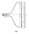
- Fig. 1 diagrammatically shows the parts which constitute a colour display tube before they are assembled to form an envelope. These parts are a display window 1, a shadow mask 2 which is secured to a frame 3, and a conical enveloping part 4 which is provided with an electrode system 5 comprising three electron guns.
- the display window 1 is provided with a display screen 6 comprising a large number of phosphor elements luminescing in red, green and blue.
- the phosphor elements may be in the form of, for example, dots or strips.
- the invention will be further described by means of strip-shaped elements the longitudinal direction of which extends perpendicularly to the plane through the electron guns (in this case, the plane of the drawing).
- the shadow mask 2 having a large number of apertures 7 is provided on the frame 3 while being subjected to mechanical tension, said frame being made of glass in the embodiment shown, but in an alternative embodiment it may also be made of metal.
- the shadow mask can be suspended in the envelope by locating the edge of the shadow mask between the upright edge and the envelope part.
- the electrode system 5 for generating three electron beams is located in the enveloping part 4 which is conically shaped in the present example but which may be, for example, box-shaped in another embodiment of the invention.
- the electrode system 5 may be arranged in the enveloping part 4 both before and after the enveloping part 4 is secured to the display window 1.
- the parts When the parts are accurately positioned relative to one another they are generally fitted to one another, a glass frit being inserted, so that an envelope is formed which is subsequently evacuated.
- the colour display tube being heated to approximately 400 o C, the shadow mask can be displaced from its accurate position relative to the display screen. In accordance with the inventive method this adverse displacement is compensated by accurately positioning the shadow mask relative to the display window after the envelope has been formed.
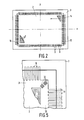
- Fig. 2 is a diagrammatic elevational view of a substantially rectangular shadow mask 2, viewed from the electrode system, which is suspended in a frame 3 using mechanical tension.
- the shadow mask 2 is provided with a number of slots 8 at all the edges, such that strips 9 are formed at the edge of the shadow mask 2.
- the shadow mask may be provided with strips, for example, at two opposite edges.
- the slots 8 extend as far as the edge of the shadow mask 2, but in an alterantive embodiment of the invention they may be located entirely in the shadow mask 2.
- the mechanical tension to which the shadow mask 2 and the strips 9 are subjected remains within the elastic range of the material used for the shadow mask 2.
- the shadow mask 2 is suspended in the frame 3 such that the strips 9 remain partly free.
- the strips may be regarded as springs.
- the tensed shadow mask 2 is in elastic equilibrium, the apertures 7 in the shadow mask 2 being in a predetermined position relative to the phosphor elements.
- these strips are made to slacken so that the equilibrium is disturbed and owing to the tension in the shadow mask 2, this shadow mask attains another equilibrium in which the apertures 7 in the shadow mask 2 are displaced relative to their previous position. For example, if energy is applied to the strips 14 and 15 (Fig. 2), these strips 14 and 15 are heated off, causing them to slacken.
- the mechanical tension used to suspend the shadow mask 2 in the frame 3 ensures that the apertures 7 in the shadow mask 2 are subject to a translation relative to the display screen in a direction along the x-axis, as is indicated by the arrows in Fig. 1.
- the strips 14 and 15 which slacken due to irradiation are stretched by this translation in the shadow mask 2 and obtain a length which corresponds to the new equilibrium.
- the magnitude of the translation may be influenced by changing the number of strips to which energy is applied.
- a translation of the apertures 7 in the shadow mask 2 in a direction along the y-axis can be carried out in an analogous manner.
- a rotation about an axis which is perpendicular to the plane which is determined by the x-axis and the y-axis is obtained, for example, by applying energy to the strips 14 and 15.
- a controlled displacement of the apertures in the shadow mask relative to the display window by deforming a number of strips can be attained when at least one of the edges of the shadow mask has strips, and it depends, inter alia, on the magnitude of the mechanical tension used to suspend the shadow mask and on the material of which the shadow mask is composed.
- a controlled positioning can be obtained when strips are used which each have a length and a width of, for example, 5 mm and 0.3 mm, respectively, and between which there is an interspace of 0.3 mm.
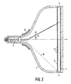
- test pattern is displayed on the display screen 6 (diagrammatically represented by the electron beams 20, 21 and 22 in Fig. 3) preferably by means of the electrode system 5.
- the test pattern may be generated by a lamp. Optimizing this test pattern is carried out, for example, as follows.
- the test pattern displayed on the display screen 6 is examined and dependent on, for example, the colour errors present the direction and the magnitude of the displacement of the shadow mask 2 can be determined, such that the apertures 7 of the shadow mask 2 are more accurately positioned relative to the phosphor elements of the display screen 6.
- the current passing through the deflection coil system 23 is adjusted by means of a control unit (not shown in Fig. 3) such that those strips of the shadow mask 2 are irradiated by an electron beam 10 which are necessary to obtain the displacements necessary.
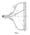
- Fig. 4 energy is alternatively applied to the strips by making a laser beam 11 generated by a laser 12 impinge on the desired strips. To this end, the laser beam 11 is passed through a light-transmitting window 13 which is provided in the conical envelope 4.
- Figure 5 is a diagrammatic representation of a corner of a shadow mask 2 having strips 9 at all the edges.
- the shadow mask 2 is secured to the frame 3, so as to be tensed at all the edges.
- stresses may occur in the corner of the shadow mask 2 which may bring about undesirable curvatures in the corner of the shadow mask.
- These undesirable curvatures may lead to colour errors in a image to be displayed.
- the corner of the shadow mask 2 is provided with recesses 32 by means of which a uniform stress distribution in the corner of the shadow mask 2 is obtained.
- the recesses 32 may be, for example, weakened portions or apertures in the shadow mask 2.
- the shape and orientation of the recesses 32 leading to a uniform stress distribution may have many different embodiments and can be determined experimentally by those skilled in the art as a function of, inter alia, the shadow mask material.
- the recesses 32 are oval apertures whose longitudinal axis extends substantially parallel to the diagonal in the relevant corner.
- the method in accordance with the invention permits an inaccurately aligned shadow mask to be accurately aligned relative to the display window, such that almost no colour errors occur during operation of the colour display tube.
Applications Claiming Priority (2)
| Application Number | Priority Date | Filing Date | Title |
|---|---|---|---|
| NL8801943A NL8801943A (nl) | 1988-08-04 | 1988-08-04 | Werkwijze voor het vervaardigen van een kleurenbeeldbuis. |
| NL8801943 | 1988-08-04 |
Publications (1)
| Publication Number | Publication Date |
|---|---|
| EP0354617A1 true EP0354617A1 (de) | 1990-02-14 |
Family
ID=19852707
Family Applications (1)
| Application Number | Title | Priority Date | Filing Date |
|---|---|---|---|
| EP89202030A Withdrawn EP0354617A1 (de) | 1988-08-04 | 1989-08-03 | Verfahren zum Herstellen einer Farbbildröhre und Farbbildröhre |
Country Status (4)
| Country | Link |
|---|---|
| US (1) | US4964828A (de) |
| EP (1) | EP0354617A1 (de) |
| JP (1) | JPH0268838A (de) |
| NL (1) | NL8801943A (de) |
Cited By (4)
| Publication number | Priority date | Publication date | Assignee | Title |
|---|---|---|---|---|
| EP0372630A2 (de) * | 1988-12-05 | 1990-06-13 | Koninklijke Philips Electronics N.V. | Schattenmaske mit Randmuster |
| WO1992019004A1 (en) * | 1991-04-15 | 1992-10-29 | Zenith Electronics Corporation | Peripheral bodies for tension mask crt panel |
| FR2756971A1 (fr) * | 1996-11-13 | 1998-06-12 | Lg Electronics Inc | Structure de masque perfore pour tube a rayons cathodiques plat |
| EP1001447A1 (de) * | 1998-10-30 | 2000-05-17 | Matsushita Electronics Corporation | Farbkathodenstrahlröhre |
Families Citing this family (4)
| Publication number | Priority date | Publication date | Assignee | Title |
|---|---|---|---|---|
| US6283814B1 (en) * | 1997-09-26 | 2001-09-04 | Samsung Display Devices Co., Ltd | Flat cathode ray tube and method of manufacturing same |
| KR100255273B1 (ko) * | 1998-01-22 | 2000-05-01 | 손욱 | 새도우 마스크 및 그의 제조 방법 |
| JP3598927B2 (ja) * | 1999-12-27 | 2004-12-08 | 松下電器産業株式会社 | シャドウマスク組立体の製造方法および陰極線管の製造方法 |
| WO2018110253A1 (ja) * | 2016-12-14 | 2018-06-21 | 大日本印刷株式会社 | 蒸着マスク装置及び蒸着マスク装置の製造方法 |
Citations (2)
| Publication number | Priority date | Publication date | Assignee | Title |
|---|---|---|---|---|
| LU53942A1 (de) * | 1966-06-23 | 1968-03-11 | ||
| EP0143938A2 (de) * | 1983-09-30 | 1985-06-12 | Zenith Electronics Corporation | Farbbildröhre, Bestandteil dafür und Verfahren zu deren Herstellung |
Family Cites Families (5)
| Publication number | Priority date | Publication date | Assignee | Title |
|---|---|---|---|---|
| US3468005A (en) * | 1966-09-20 | 1969-09-23 | Sylvania Electric Prod | Process for improving mask-screen registration in cathode ray tubes |
| US3643299A (en) * | 1969-06-16 | 1972-02-22 | Rca Corp | Electron beam tube and method of adjusting the electrode spacing of an electron gun therein |
| JPS5257776A (en) * | 1975-11-06 | 1977-05-12 | Matsushita Electronics Corp | Shadow mask for color picture tube |
| US4652791A (en) * | 1985-04-30 | 1987-03-24 | Zenith Electronics Corporation | Color cathode ray tube and tensible shadow mask blank for use therein |
| US4756702A (en) * | 1986-12-31 | 1988-07-12 | Zenith Electronics Corporation | Pretreatment process for flat tension mask |
-
1988
- 1988-08-04 NL NL8801943A patent/NL8801943A/nl not_active Application Discontinuation
-
1989
- 1989-08-03 EP EP89202030A patent/EP0354617A1/de not_active Withdrawn
- 1989-08-04 US US07/389,724 patent/US4964828A/en not_active Expired - Fee Related
- 1989-08-04 JP JP1201458A patent/JPH0268838A/ja active Pending
Patent Citations (2)
| Publication number | Priority date | Publication date | Assignee | Title |
|---|---|---|---|---|
| LU53942A1 (de) * | 1966-06-23 | 1968-03-11 | ||
| EP0143938A2 (de) * | 1983-09-30 | 1985-06-12 | Zenith Electronics Corporation | Farbbildröhre, Bestandteil dafür und Verfahren zu deren Herstellung |
Cited By (7)
| Publication number | Priority date | Publication date | Assignee | Title |
|---|---|---|---|---|
| EP0372630A2 (de) * | 1988-12-05 | 1990-06-13 | Koninklijke Philips Electronics N.V. | Schattenmaske mit Randmuster |
| EP0372630A3 (de) * | 1988-12-05 | 1991-06-05 | Koninklijke Philips Electronics N.V. | Schattenmaske mit Randmuster |
| WO1992019004A1 (en) * | 1991-04-15 | 1992-10-29 | Zenith Electronics Corporation | Peripheral bodies for tension mask crt panel |
| FR2756971A1 (fr) * | 1996-11-13 | 1998-06-12 | Lg Electronics Inc | Structure de masque perfore pour tube a rayons cathodiques plat |
| EP1001447A1 (de) * | 1998-10-30 | 2000-05-17 | Matsushita Electronics Corporation | Farbkathodenstrahlröhre |
| US6573644B1 (en) | 1998-10-30 | 2003-06-03 | Matsushita Electric Industrial Co., Ltd. | Color cathode ray tube having a one-dimensional tension mask with a perforated region |
| CN1110834C (zh) * | 1998-10-30 | 2003-06-04 | 松下电器产业株式会社 | 彩色阴极射线管 |
Also Published As
| Publication number | Publication date |
|---|---|
| US4964828A (en) | 1990-10-23 |
| NL8801943A (nl) | 1990-03-01 |
| JPH0268838A (ja) | 1990-03-08 |
Similar Documents
| Publication | Publication Date | Title |
|---|---|---|
| US3894321A (en) | Method for processing a color cathode ray tube having a thin foil mask sealed directly to the bulb | |
| CA1220507A (en) | Flat square cathode ray tube | |
| EP0354617A1 (de) | Verfahren zum Herstellen einer Farbbildröhre und Farbbildröhre | |
| US4591344A (en) | Method of fabricating a tension mask color cathode ray tube | |
| EP0355893A1 (de) | Verfahren zum Herstellen einer Farbbildröhre | |
| GB2052148A (en) | Colour cathode ray tubes | |
| JPH01274343A (ja) | Crtテンションマスクおよびその基準および支持システム | |
| US5350970A (en) | Display tube having a detachable getter | |
| US4902257A (en) | Methods and apparatus for making flat tension mask color cathode ray tubes | |
| US4656389A (en) | Tensed mask cathode ray tube | |
| CA1315333C (en) | Method and apparatus of assuring interchangeability of shadow masks and front panels in the manufacture of color cathode ray tubes | |
| US3501663A (en) | Parallax barrier protecting means for cathode ray tubes having patterned screens | |
| US6013975A (en) | Color display tube having a shadow mask | |
| EP0382308B1 (de) | Kathodenstrahlröhrenschirm-Beschichtungseinrichtung und Methode | |
| KR100272722B1 (ko) | 컬러 수상관 및 그 제조방법 | |
| EP0211963B1 (de) | Farbbildkathodenstrahlröhre, Komponente dafür und ihr Herstellungsverfahren | |
| US2903319A (en) | Image reproduction device | |
| US4721879A (en) | Tensed mask cathode ray tube | |
| EP0296657B1 (de) | Verfahren zur Herstellung einer Elektronenstrahlröhre und Elektronenstrahlröhre, hergestellt mit einem derartigen Verfahren | |
| EP0251404B1 (de) | Verfahren zur Herstellung einer Kathodestrahlröhre | |
| JPS6345741A (ja) | カラ−陰極線管シャドウマスク、カラ−陰極線管の前面組立体及び超高解像度カラ−陰極線管のほぼ平らなフェイスプレ−トを製作する方法 | |
| US4891548A (en) | Tension mask color cathode ray tube component with external registration-affording means | |
| US4695523A (en) | Method of screening a flat mask cathode ray tube | |
| US4723089A (en) | Removable screening mount for a tensed mask cathode ray tube | |
| US5030154A (en) | Method of mounting tensed CRT mask |
Legal Events
| Date | Code | Title | Description |
|---|---|---|---|
| PUAI | Public reference made under article 153(3) epc to a published international application that has entered the european phase |
Free format text: ORIGINAL CODE: 0009012 |
|
| AK | Designated contracting states |
Kind code of ref document: A1 Designated state(s): DE FR GB NL |
|
| 17P | Request for examination filed |
Effective date: 19900807 |
|
| 17Q | First examination report despatched |
Effective date: 19920916 |
|
| STAA | Information on the status of an ep patent application or granted ep patent |
Free format text: STATUS: THE APPLICATION IS DEEMED TO BE WITHDRAWN |
|
| 18D | Application deemed to be withdrawn |
Effective date: 19930127 |