EP0354189A2 - A transverse suspension for railway vehicles - Google Patents
A transverse suspension for railway vehicles Download PDFInfo
- Publication number
- EP0354189A2 EP0354189A2 EP89830276A EP89830276A EP0354189A2 EP 0354189 A2 EP0354189 A2 EP 0354189A2 EP 89830276 A EP89830276 A EP 89830276A EP 89830276 A EP89830276 A EP 89830276A EP 0354189 A2 EP0354189 A2 EP 0354189A2
- Authority
- EP
- European Patent Office
- Prior art keywords
- bogie
- torsion bar
- transverse
- vehicle
- suspension
- Prior art date
- Legal status (The legal status is an assumption and is not a legal conclusion. Google has not performed a legal analysis and makes no representation as to the accuracy of the status listed.)
- Granted
Links
Images
Classifications
-
- B—PERFORMING OPERATIONS; TRANSPORTING
- B61—RAILWAYS
- B61F—RAIL VEHICLE SUSPENSIONS, e.g. UNDERFRAMES, BOGIES OR ARRANGEMENTS OF WHEEL AXLES; RAIL VEHICLES FOR USE ON TRACKS OF DIFFERENT WIDTH; PREVENTING DERAILING OF RAIL VEHICLES; WHEEL GUARDS, OBSTRUCTION REMOVERS OR THE LIKE FOR RAIL VEHICLES
- B61F5/00—Constructional details of bogies; Connections between bogies and vehicle underframes; Arrangements or devices for adjusting or allowing self-adjustment of wheel axles or bogies when rounding curves
- B61F5/02—Arrangements permitting limited transverse relative movements between vehicle underframe or bolster and bogie; Connections between underframes and bogies
- B61F5/22—Guiding of the vehicle underframes with respect to the bogies
- B61F5/24—Means for damping or minimising the canting, skewing, pitching, or plunging movements of the underframes
Definitions
- the present invention relates to a transverse suspension for railway vehicles.
- transverse suspension of a railway vehicle is usually constituted by devices with helical or rubber springs which act in parallel with the secondary suspension between the structure of each bogie and the body of the vehicle.
- the subject of the present invention is a suspension for railway vehicles, characterised in that it includes a torsion bar mounted on one of the body and the bogie and means for connecting the torsion bar to the other of the bogie and the body.
- the torsion bar is arranged parallel to the longitudinal axis of the vehicle with its ends fitted tightly into attachments fixed to the body
- the connection means comprise a substantially vertical lever with one end keyed to the torsion bar, and a shaft arranged substantially parallel to the transverse axis of the vehicle with its ends articulated to the frame of the bogie and to the other end of the lever respectively.
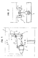
- the lower part of the body of a railway vehicle is schematically indicated 1 and a part of the structure of one of its bogies is indicated 2, a transverse suspension 3 according to the invention being interposed between them.
- two suspensions 3 are normally associated with each of the vehicle bogies and are situated symmetrically on opposite sides close to the sides of the body 1.
- the transverse suspension 3 comprises essentially a torsion bar 4 arranged parallel to the longitudinal axis of the vehicle with its ends tightly fitted into a pair of attachments 5 carried by a bracket 6 of the body 1.
- the upper end of a lever 7 is keyed to the torsion bar 4 and is arranged substantially vertically, its lower end being articulated to one end of a shaft 8 which is arranged substantially parallel to the transverse axis of the vehicle.
- the opposite end of the shaft 8 is articulated at 9 to the frame of the bogie 2.
- the relative transverse movements between the body 1 and the bogie 2 are resiliently opposed by corresponding torsional deformations of the bar 4, achieved by the transmission constituted by the lever 7 and the shaft 8.
- the suspension 3 may also be equipped with a transverse shock-absorber 10 interposed between the body 1 and the frame of the bogie 2 as shown in Figure 1.
Landscapes
- Engineering & Computer Science (AREA)
- Mechanical Engineering (AREA)
- Vehicle Body Suspensions (AREA)
- Springs (AREA)
- Vehicle Interior And Exterior Ornaments, Soundproofing, And Insulation (AREA)
- Train Traffic Observation, Control, And Security (AREA)
- Communication Control (AREA)
- Axle Suspensions And Sidecars For Cycles (AREA)
Abstract
Description
- The present invention relates to a transverse suspension for railway vehicles.
- Conventionally the transverse suspension of a railway vehicle is usually constituted by devices with helical or rubber springs which act in parallel with the secondary suspension between the structure of each bogie and the body of the vehicle.
- These solutions normally involve relative sliding between the body and the bogie which can give rise to slackness due to wear and to the transmission of vibrations.
- In order to avoid this problem, the subject of the present invention is a suspension for railway vehicles, characterised in that it includes a torsion bar mounted on one of the body and the bogie and means for connecting the torsion bar to the other of the bogie and the body.
- The advantage of this solution lies in the fact that in all the relative body-bogie movements, the transverse forces between the body and the bogie are applied without causing any relative sliding with the problems which could result therefrom.
- According to a preferred embodiment of the invention, the torsion bar is arranged parallel to the longitudinal axis of the vehicle with its ends fitted tightly into attachments fixed to the body, and the connection means comprise a substantially vertical lever with one end keyed to the torsion bar, and a shaft arranged substantially parallel to the transverse axis of the vehicle with its ends articulated to the frame of the bogie and to the other end of the lever respectively.
- The invention will now be described in detail with reference to the appended drawings provided purely by way of non-limiting example, in which:
- Figure 1 is a schematic cross-section of part of a railway vehicle provided with a transverse suspension according to the invention, and
- Figure 2 is a section taken on the line II-II of Figure 1.
- With reference to the drawings, the lower part of the body of a railway vehicle is schematically indicated 1 and a part of the structure of one of its bogies is indicated 2, a
transverse suspension 3 according to the invention being interposed between them. It should be noted that twosuspensions 3 are normally associated with each of the vehicle bogies and are situated symmetrically on opposite sides close to the sides of the body 1. - The
transverse suspension 3 comprises essentially atorsion bar 4 arranged parallel to the longitudinal axis of the vehicle with its ends tightly fitted into a pair ofattachments 5 carried by abracket 6 of the body 1. The upper end of alever 7 is keyed to thetorsion bar 4 and is arranged substantially vertically, its lower end being articulated to one end of ashaft 8 which is arranged substantially parallel to the transverse axis of the vehicle. The opposite end of theshaft 8 is articulated at 9 to the frame of thebogie 2. - In operation, the relative transverse movements between the body 1 and the
bogie 2 are resiliently opposed by corresponding torsional deformations of thebar 4, achieved by the transmission constituted by thelever 7 and theshaft 8. - The
suspension 3 may also be equipped with a transverse shock-absorber 10 interposed between the body 1 and the frame of thebogie 2 as shown in Figure 1.
Claims (2)
Priority Applications (1)
| Application Number | Priority Date | Filing Date | Title |
|---|---|---|---|
| AT89830276T ATE82726T1 (en) | 1988-08-04 | 1989-06-20 | CROSS SUSPENSION FOR RAIL VEHICLES. |
Applications Claiming Priority (2)
| Application Number | Priority Date | Filing Date | Title |
|---|---|---|---|
| IT8853348U IT215083Z2 (en) | 1988-08-04 | 1988-08-04 | TRANSVERSAL SUSPENSION FOR RAILWAY VEHICLES |
| IT5334888U | 1988-08-04 |
Publications (3)
| Publication Number | Publication Date |
|---|---|
| EP0354189A2 true EP0354189A2 (en) | 1990-02-07 |
| EP0354189A3 EP0354189A3 (en) | 1990-06-20 |
| EP0354189B1 EP0354189B1 (en) | 1992-11-25 |
Family
ID=11282019
Family Applications (1)
| Application Number | Title | Priority Date | Filing Date |
|---|---|---|---|
| EP89830276A Expired - Lifetime EP0354189B1 (en) | 1988-08-04 | 1989-06-20 | A transverse suspension for railway vehicles |
Country Status (6)
| Country | Link |
|---|---|
| EP (1) | EP0354189B1 (en) |
| AT (1) | ATE82726T1 (en) |
| DE (1) | DE68903611T2 (en) |
| ES (1) | ES2036054T3 (en) |
| GR (1) | GR3006600T3 (en) |
| IT (1) | IT215083Z2 (en) |
Cited By (2)
| Publication number | Priority date | Publication date | Assignee | Title |
|---|---|---|---|---|
| CN102991520A (en) * | 2012-11-21 | 2013-03-27 | 南车南京浦镇车辆有限公司 | Mounting structure for anti-side-rolling torsion bar base of railway vehicle |
| CN108909752A (en) * | 2018-07-23 | 2018-11-30 | 株洲时代新材料科技股份有限公司 | Anti-side rolling torsion bar for railway vehicle support component, installation method and product |
Citations (4)
| Publication number | Priority date | Publication date | Assignee | Title |
|---|---|---|---|---|
| GB163009A (en) * | 1920-05-08 | 1922-06-29 | Paul Jules Leboucher | System of elastic lateral balancing of vehicles with bogies |
| DE1293806B (en) * | 1962-09-07 | 1969-04-30 | Krauss Maffei Ag | Trunnion-free bogie guide for rail vehicles |
| DE2421874A1 (en) * | 1974-05-06 | 1976-04-08 | Maschf Augsburg Nuernberg Ag | High speed railway rolling-stock stabiliser - has bogie frame mounted and body mounted components hinged on both sides |
| GB2045189A (en) * | 1979-03-23 | 1980-10-29 | Coal Industry Patents Ltd | Rail vehicle suspensions |
-
1988
- 1988-08-04 IT IT8853348U patent/IT215083Z2/en active
-
1989
- 1989-06-20 AT AT89830276T patent/ATE82726T1/en not_active IP Right Cessation
- 1989-06-20 EP EP89830276A patent/EP0354189B1/en not_active Expired - Lifetime
- 1989-06-20 ES ES198989830276T patent/ES2036054T3/en not_active Expired - Lifetime
- 1989-06-20 DE DE8989830276T patent/DE68903611T2/en not_active Expired - Fee Related
-
1992
- 1992-12-21 GR GR920403008T patent/GR3006600T3/el unknown
Patent Citations (4)
| Publication number | Priority date | Publication date | Assignee | Title |
|---|---|---|---|---|
| GB163009A (en) * | 1920-05-08 | 1922-06-29 | Paul Jules Leboucher | System of elastic lateral balancing of vehicles with bogies |
| DE1293806B (en) * | 1962-09-07 | 1969-04-30 | Krauss Maffei Ag | Trunnion-free bogie guide for rail vehicles |
| DE2421874A1 (en) * | 1974-05-06 | 1976-04-08 | Maschf Augsburg Nuernberg Ag | High speed railway rolling-stock stabiliser - has bogie frame mounted and body mounted components hinged on both sides |
| GB2045189A (en) * | 1979-03-23 | 1980-10-29 | Coal Industry Patents Ltd | Rail vehicle suspensions |
Cited By (3)
| Publication number | Priority date | Publication date | Assignee | Title |
|---|---|---|---|---|
| CN102991520A (en) * | 2012-11-21 | 2013-03-27 | 南车南京浦镇车辆有限公司 | Mounting structure for anti-side-rolling torsion bar base of railway vehicle |
| CN102991520B (en) * | 2012-11-21 | 2015-06-03 | 南车南京浦镇车辆有限公司 | Mounting structure for anti-side-rolling torsion bar base of railway vehicle |
| CN108909752A (en) * | 2018-07-23 | 2018-11-30 | 株洲时代新材料科技股份有限公司 | Anti-side rolling torsion bar for railway vehicle support component, installation method and product |
Also Published As
| Publication number | Publication date |
|---|---|
| DE68903611D1 (en) | 1993-01-07 |
| IT8853348V0 (en) | 1988-08-04 |
| DE68903611T2 (en) | 1993-04-01 |
| ATE82726T1 (en) | 1992-12-15 |
| ES2036054T3 (en) | 1993-05-01 |
| EP0354189B1 (en) | 1992-11-25 |
| GR3006600T3 (en) | 1993-06-30 |
| EP0354189A3 (en) | 1990-06-20 |
| IT215083Z2 (en) | 1990-07-30 |
Similar Documents
| Publication | Publication Date | Title |
|---|---|---|
| US5415107A (en) | Running gear for drop-frame rail vehicles | |
| CA1148029A (en) | Bolsterless bogie with air-spring suspension for rail vehicles | |
| EP1583672A1 (en) | Shackle assembly | |
| US4841874A (en) | Pneumatic-spring bogie | |
| RU2203818C2 (en) | Running part of rail vehicle bogie | |
| US20050116436A1 (en) | Flexible connection device between a bogey side beam and an axle-box | |
| US5327837A (en) | Bolster of a railroad car truck with varying cross-sectional shape to provide less torsional rigidity at ends | |
| US2689015A (en) | Axle suspension for motor vehicles | |
| HUT66343A (en) | Bogie for high-speed railrway vehicles | |
| EP0189382A2 (en) | High-speed railway vehicle with a variable-attitude body | |
| JP2655730B2 (en) | Railcar | |
| US5638757A (en) | Rail vehicle and truck for such a vehicle | |
| EP0354189B1 (en) | A transverse suspension for railway vehicles | |
| EP0016469A1 (en) | Device for resiliently supporting a torsionally rigid superstructure on a torsionally yieldable chassis frame of load-carrying vehicles | |
| US20030033955A1 (en) | Running gear for a rail vehicle | |
| JP3498258B2 (en) | 2-axle bogie for railway vehicles | |
| US2260508A (en) | Springing for railway trucks | |
| US4458861A (en) | Anti-vibratory suspension device for a helicopter | |
| US3952670A (en) | Railway vehicle primary suspensions | |
| EP0563810A1 (en) | A suspension device for a pair of steered front wheels for a commercial vehicle | |
| EP0760323A2 (en) | Running gear with attachment of a single axle especially for two axled or articulated railway vehicles | |
| EP0177460B1 (en) | Bogie for railway vehicles with independent wheels | |
| EP0357564B1 (en) | A motor bogie for railway vehicles | |
| US4519628A (en) | Vehicle suspensions | |
| EP0271451A2 (en) | Bogie for railway vehicle |
Legal Events
| Date | Code | Title | Description |
|---|---|---|---|
| PUAI | Public reference made under article 153(3) epc to a published international application that has entered the european phase |
Free format text: ORIGINAL CODE: 0009012 |
|
| AK | Designated contracting states |
Kind code of ref document: A2 Designated state(s): AT BE CH DE ES FR GB GR IT LI LU NL SE |
|
| PUAL | Search report despatched |
Free format text: ORIGINAL CODE: 0009013 |
|
| AK | Designated contracting states |
Kind code of ref document: A3 Designated state(s): AT BE CH DE ES FR GB GR IT LI LU NL SE |
|
| 17P | Request for examination filed |
Effective date: 19900919 |
|
| 17Q | First examination report despatched |
Effective date: 19920206 |
|
| GRAA | (expected) grant |
Free format text: ORIGINAL CODE: 0009210 |
|
| AK | Designated contracting states |
Kind code of ref document: B1 Designated state(s): AT BE CH DE ES FR GB GR IT LI LU NL SE |
|
| REF | Corresponds to: |
Ref document number: 82726 Country of ref document: AT Date of ref document: 19921215 Kind code of ref document: T |
|
| ITF | It: translation for a ep patent filed |
Owner name: JACOBACCI & PERANI S.P.A. |
|
| REF | Corresponds to: |
Ref document number: 68903611 Country of ref document: DE Date of ref document: 19930107 |
|
| ET | Fr: translation filed | ||
| REG | Reference to a national code |
Ref country code: ES Ref legal event code: FG2A Ref document number: 2036054 Country of ref document: ES Kind code of ref document: T3 |
|
| REG | Reference to a national code |
Ref country code: GR Ref legal event code: FG4A Free format text: 3006600 |
|
| PLBE | No opposition filed within time limit |
Free format text: ORIGINAL CODE: 0009261 |
|
| STAA | Information on the status of an ep patent application or granted ep patent |
Free format text: STATUS: NO OPPOSITION FILED WITHIN TIME LIMIT |
|
| 26N | No opposition filed | ||
| EPTA | Lu: last paid annual fee | ||
| EAL | Se: european patent in force in sweden |
Ref document number: 89830276.5 |
|
| PGFP | Annual fee paid to national office [announced via postgrant information from national office to epo] |
Ref country code: SE Payment date: 19980507 Year of fee payment: 10 |
|
| PGFP | Annual fee paid to national office [announced via postgrant information from national office to epo] |
Ref country code: AT Payment date: 19980513 Year of fee payment: 10 |
|
| PGFP | Annual fee paid to national office [announced via postgrant information from national office to epo] |
Ref country code: GB Payment date: 19980522 Year of fee payment: 10 |
|
| PGFP | Annual fee paid to national office [announced via postgrant information from national office to epo] |
Ref country code: NL Payment date: 19980527 Year of fee payment: 10 |
|
| PGFP | Annual fee paid to national office [announced via postgrant information from national office to epo] |
Ref country code: DE Payment date: 19980528 Year of fee payment: 10 |
|
| PGFP | Annual fee paid to national office [announced via postgrant information from national office to epo] |
Ref country code: GR Payment date: 19980529 Year of fee payment: 10 Ref country code: CH Payment date: 19980529 Year of fee payment: 10 |
|
| PGFP | Annual fee paid to national office [announced via postgrant information from national office to epo] |
Ref country code: BE Payment date: 19980604 Year of fee payment: 10 |
|
| PGFP | Annual fee paid to national office [announced via postgrant information from national office to epo] |
Ref country code: ES Payment date: 19980616 Year of fee payment: 10 |
|
| PGFP | Annual fee paid to national office [announced via postgrant information from national office to epo] |
Ref country code: FR Payment date: 19980630 Year of fee payment: 10 |
|
| PGFP | Annual fee paid to national office [announced via postgrant information from national office to epo] |
Ref country code: LU Payment date: 19981021 Year of fee payment: 10 |
|
| PG25 | Lapsed in a contracting state [announced via postgrant information from national office to epo] |
Ref country code: LU Free format text: LAPSE BECAUSE OF NON-PAYMENT OF DUE FEES Effective date: 19990620 Ref country code: GB Free format text: LAPSE BECAUSE OF NON-PAYMENT OF DUE FEES Effective date: 19990620 Ref country code: AT Free format text: LAPSE BECAUSE OF NON-PAYMENT OF DUE FEES Effective date: 19990620 |
|
| PG25 | Lapsed in a contracting state [announced via postgrant information from national office to epo] |
Ref country code: ES Free format text: LAPSE BECAUSE OF EXPIRATION OF PROTECTION Effective date: 19990621 |
|
| PG25 | Lapsed in a contracting state [announced via postgrant information from national office to epo] |
Ref country code: SE Free format text: THE PATENT HAS BEEN ANNULLED BY A DECISION OF A NATIONAL AUTHORITY Effective date: 19990629 |
|
| PG25 | Lapsed in a contracting state [announced via postgrant information from national office to epo] |
Ref country code: LI Free format text: LAPSE BECAUSE OF NON-PAYMENT OF DUE FEES Effective date: 19990630 Ref country code: GR Free format text: LAPSE BECAUSE OF NON-PAYMENT OF DUE FEES Effective date: 19990630 Ref country code: FR Free format text: THE PATENT HAS BEEN ANNULLED BY A DECISION OF A NATIONAL AUTHORITY Effective date: 19990630 Ref country code: CH Free format text: LAPSE BECAUSE OF NON-PAYMENT OF DUE FEES Effective date: 19990630 Ref country code: BE Free format text: LAPSE BECAUSE OF NON-PAYMENT OF DUE FEES Effective date: 19990630 |
|
| BERE | Be: lapsed |
Owner name: FIAT FERROVIARIA S.P.A. Effective date: 19990630 |
|
| PG25 | Lapsed in a contracting state [announced via postgrant information from national office to epo] |
Ref country code: NL Free format text: LAPSE BECAUSE OF NON-PAYMENT OF DUE FEES Effective date: 20000101 |
|
| GBPC | Gb: european patent ceased through non-payment of renewal fee |
Effective date: 19990620 |
|
| REG | Reference to a national code |
Ref country code: CH Ref legal event code: PL |
|
| EUG | Se: european patent has lapsed |
Ref document number: 89830276.5 |
|
| NLV4 | Nl: lapsed or anulled due to non-payment of the annual fee |
Effective date: 20000101 |
|
| PG25 | Lapsed in a contracting state [announced via postgrant information from national office to epo] |
Ref country code: DE Free format text: LAPSE BECAUSE OF NON-PAYMENT OF DUE FEES Effective date: 20000503 |
|
| REG | Reference to a national code |
Ref country code: FR Ref legal event code: ST |
|
| REG | Reference to a national code |
Ref country code: ES Ref legal event code: FD2A Effective date: 20010601 |
|
| PG25 | Lapsed in a contracting state [announced via postgrant information from national office to epo] |
Ref country code: IT Free format text: LAPSE BECAUSE OF NON-PAYMENT OF DUE FEES;WARNING: LAPSES OF ITALIAN PATENTS WITH EFFECTIVE DATE BEFORE 2007 MAY HAVE OCCURRED AT ANY TIME BEFORE 2007. THE CORRECT EFFECTIVE DATE MAY BE DIFFERENT FROM THE ONE RECORDED. Effective date: 20050620 |