EP0353784B1 - Enclosures for high-speed winders - Google Patents
Enclosures for high-speed winders Download PDFInfo
- Publication number
- EP0353784B1 EP0353784B1 EP89116614A EP89116614A EP0353784B1 EP 0353784 B1 EP0353784 B1 EP 0353784B1 EP 89116614 A EP89116614 A EP 89116614A EP 89116614 A EP89116614 A EP 89116614A EP 0353784 B1 EP0353784 B1 EP 0353784B1
- Authority
- EP
- European Patent Office
- Prior art keywords
- chuck
- door
- machine
- operating region
- doffing
- Prior art date
- Legal status (The legal status is an assumption and is not a legal conclusion. Google has not performed a legal analysis and makes no representation as to the accuracy of the status listed.)
- Expired - Lifetime
Links
- 238000004804 winding Methods 0.000 claims description 47
- 230000000717 retained effect Effects 0.000 claims description 2
- 230000007246 mechanism Effects 0.000 description 22
- 238000012986 modification Methods 0.000 description 5
- 230000004048 modification Effects 0.000 description 5
- 238000004891 communication Methods 0.000 description 4
- 238000013461 design Methods 0.000 description 4
- 238000010586 diagram Methods 0.000 description 4
- 238000009434 installation Methods 0.000 description 3
- 238000009940 knitting Methods 0.000 description 3
- 239000003550 marker Substances 0.000 description 3
- 238000004378 air conditioning Methods 0.000 description 2
- 238000011161 development Methods 0.000 description 2
- 230000018109 developmental process Effects 0.000 description 2
- 230000006872 improvement Effects 0.000 description 2
- 238000001208 nuclear magnetic resonance pulse sequence Methods 0.000 description 2
- 230000004044 response Effects 0.000 description 2
- 238000007789 sealing Methods 0.000 description 2
- 238000012546 transfer Methods 0.000 description 2
- 230000015572 biosynthetic process Effects 0.000 description 1
- 230000000903 blocking effect Effects 0.000 description 1
- 230000003750 conditioning effect Effects 0.000 description 1
- 238000010276 construction Methods 0.000 description 1
- 239000000428 dust Substances 0.000 description 1
- 230000007613 environmental effect Effects 0.000 description 1
- 238000009730 filament winding Methods 0.000 description 1
- 239000012530 fluid Substances 0.000 description 1
- 230000000977 initiatory effect Effects 0.000 description 1
- 230000002452 interceptive effect Effects 0.000 description 1
- 238000012423 maintenance Methods 0.000 description 1
- 230000013011 mating Effects 0.000 description 1
- 239000002184 metal Substances 0.000 description 1
- 230000035515 penetration Effects 0.000 description 1
- 230000020347 spindle assembly Effects 0.000 description 1
- 239000004753 textile Substances 0.000 description 1
- 230000001960 triggered effect Effects 0.000 description 1
Images


Classifications
-
- B—PERFORMING OPERATIONS; TRANSPORTING
- B65—CONVEYING; PACKING; STORING; HANDLING THIN OR FILAMENTARY MATERIAL
- B65H—HANDLING THIN OR FILAMENTARY MATERIAL, e.g. SHEETS, WEBS, CABLES
- B65H54/00—Winding, coiling, or depositing filamentary material
- B65H54/70—Other constructional features of yarn-winding machines
- B65H54/72—Framework; Casings; Coverings
-
- B—PERFORMING OPERATIONS; TRANSPORTING
- B65—CONVEYING; PACKING; STORING; HANDLING THIN OR FILAMENTARY MATERIAL
- B65H—HANDLING THIN OR FILAMENTARY MATERIAL, e.g. SHEETS, WEBS, CABLES
- B65H2701/00—Handled material; Storage means
- B65H2701/30—Handled filamentary material
- B65H2701/31—Textiles threads or artificial strands of filaments
Definitions
- the present invention relates to improvements in enclosures for the operating regions of high-speed winding machines, for example take-up winders for threads of synthetic filament.
- high-speed refers generally to speeds in excess of 2000 m/min, but especially to speeds in excess of 4000 m/min.
- Enclosure of the main drives and ancillary service parts of textile machines has of course been common practice since the inception of such machines. Enclosure of the "operating regions" of those machines, for example the regions in which thread is spun and/or wound, is much less common, but has been proposed for a number of different purposes. For example, in United States Patent 3146572, it is proposed that raisable and lowerable shutters should be used to define an enclosed space containing the machine, which space can be controllably climatised in use. The shutters can be raised and/or lowered in order to provide access to the relevant operating regions when required. The arrangement has not found wide acceptance in the industry.
- United States Patent 3782087 describes a twisting machine in which selected regions of the machine, especially the spindle assemblies, are selectively shielded to control noise emission. Raisable and lowerable shutters are again shown in Figs. 10 to 16 of this patent.
- US Patent 3274803 describes a knitting machine in which the actual knitting region is enclosed to protect it from dust penetration, the enclosure including horizontally slidable transparent doors enabling selective access to the knitting region.
- US 2971710 shwos a wire winder having a safety slider plate slidable from side to side of the winder assembly in front of the winding heads.
- a winding head cannot be energised unless the plate is in a position which partly blocks access to the relevant winder head from the front thereof.
- the present invention provides a thread winding machine with enclosure.
- One function of the enclosure is to limit or control noise emission from the operating region of the winder.
- a second, and possibly more important function is to improve safety in operation by enabling only predetermined access to the operating region.
- the above-mentioned functions are to be enabled in a layout which is economical in space. This is frequently very significant, for example when space is at a premium in layout of a complete installation comprising a large number of take-up winders located in a "battery".
- the invention provides a machine for winding thread comprising an operating region in which thread packages are formed and retained, if necessary, to await doffing thereof.
- an operating region In the operating region, there is at least one chuck rotatable about a longitudinal chuck axis for winding of thread into a package thereon.
- the chuck has a pretedermined doffing position in the operating region; the chuck is located in this position during removal of completed thread packages therefrom.
- the invention is characterised in that an enclosure is provided and comprises at least one access door openable to enable access to the doffing position of said chuck and controllably releasable retaining means is provided for the door.
- the retaining means is operable to retain the door in a condition closing the enclosure and to release the door to permit opening thereof to provide access to said chuck for removal of a completed package therefrom.
- the arrangement is such that the door cannot be released unless the chuck is in a predetermined condition, for example located in its doffing position and at a standstill.
- the invention is intended particularly, but not exclusively, for application to a winder in which at least two chucks are provided in the operating region, each chuck being rotatable about its respective longitudinal chuck axis and being operable to wind packages sequentially to enable virtually continuous winding of thread.
- the operating region may contain other operating elements for cooperation with the chuck or with a thread during package winding, for example a friction drive roller for contacting the circumference of a package during winding thereof and/or a traverse mechanism for traversing a thread longitudinally of the chuck axis during package winding.
- control means may also be operable to control a drive means for driving the chuck.
- a sensor means is provided responsive to the condition of the door, and the control means is responsive to the sensor means so that the chuck drive means cannot be energised unless the door is in a predetermined condition, for example closed.
- the enclosure comprises a "front wall" through which selected access to the operating region is to be enabled.
- the enclosure preferably comprises continuous side walls which do not enable access to the operating region when they are in place.
- a top wall of the enclosure may be either continuous, preventing access to the operating region, or may have very limited access openings for certain specific functions, for example in threading up.
- the rear of the operating region preferably adjoins a head stock and the operating region enclosure then preferably merges into a head stock enclosure.
- the enclosure may comprise a bottom plate, but this may be omitted where the machine is designed to stand upon an adequate base, for example a floor. The remaining walls of the enclosure can then form a hood closely approaching this base at its lowermost edges.
- the present invention is intended particularly, but not exclusively, for application to the former type of winder where safety aspects are especially important during doffing (removal) of completed filament packages from one chuck during an ongoing winding operation on the other chuck.
- One design of continuous winder is shown in European Patent Application No. 73930, which is hereinafter referred to as "the prior application”.
- the invention can be applied to alternative designs of continuous winder, for example the so-called “revolver” type, an example of which is illustrated in United States Patent 4298171. Still further possibilities will be referred to towards the end of the description, including the application of the principles of the invention to single-chuck type winders, for example as illustrated in United States Patent No. 4347989.
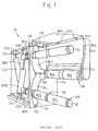
- Fig. 1 is a copy of Fig. 8 of European Published Patent Application No. 73930, but certain reference numerals have been changed to avoid conflict of usage with reference numerals used in other Figures of this application. Since full details of the machine are available from the published European Patent Specification, only a very brief outline will be repeated in this specification.
- Numeral 16 indicates a head stock housing containing drive systems, control systems and supports for the major operating elements which project forwardly from the front face of the head stock housing. Only some of those systems and supports have been shown in Fig. 1.
- FIG. 1 the front face of the head stock housing 16 is represented by a plate 310 having slots 312, 314 for a purpose to be described. Slots 312, 314 converge towards and run into each other adjacent a friction drive roll 18 extending forrwardly from plate 310. Roll 18 is supported at one end (by means not shown) in the head stock housing 16, and at the other end in a support structure 300 which projects cantilever-fashion from the front face of the housing. Drive roll 18 can be driven into rotation about its longitudinal axis (not shown) by means of a drive shaft 316 extending into the housing 16 to a non-illustrated (conventional) drive means therein.
- each chuck carries bobbin tubes (two of which are shown at 302 on the lower chuck 26) upon which respective thread packages are wound.
- each chuck is movable along its respective slot between a doffing position (in which the chuck is at the end of its slot remote from the drive roll 18, as illustrated in Fig. 1) and a position in which the tubes 302 are brought into contact with respective drive regions 304 formed on the drive roll 18.
- the chucks are brought alternately into the winding condition, that is into winding contact with the drive roll 18. While one chuck is in the winding condition, the other is maintained in its doffing position.
- a changeover operation is effected so that the threads are transferred from the one chuck to the other as the latter is moved into its winding condition. Details of the changeover operation are provided in European Patent Application No. 73930.
- the chuck bearing the completed packages (the "outgoing" chuck) is returned to its doffing position while winding of thread continues on the other chuck.
- release mechanisms within the chuck structure release the packages formed thereon, and these can be pushed off the chuck on command by the appropriate one of a pair of push-out shoes 118 associated with the respective doffing positions.
- An operating shaft for reciprocating the lower shoe 118 longitudinally of its respective chuck 26 is indicated at 120, and a similar operating shaft is provided for the upper shoe.
- a conventional traverse mechanism also projects forwardly from that plate, but in Fig. 1 this mechanism is hidden behind the support structure 300.
- the threads delivered to the chucks 24, 26 pass downwardly behind structure 300, between the traverse mechanism and that structure, around drive roll 18 and into their respective packages.
- Two bobbin tubes 302 have been illustrated in Fig. 2 merely by way of example. In practice, only one package may be formed per chuck, or there may be more than two packages (commonly up to 8) per chuck. For ease of description, in the remainder of this specification only a single thread will be referred to. It will be understood, however, that all operations described for this thread apply equally to any other threads wound simultaneously.
- each chuck 24, 26 is supported on a respective swing-arm (not shown) within housing 16.
- Chuck 24 is secured to its swing-arm by a set of clamping jaws 354, and a similar set of jaws (but without reference numeral) is illustrated for chuck 26.
- the swing-arm bearing chuck 24 can be moved through a defined swing-angle (sufficient to move the chuck from its doffing position into the winding condition) by a piston and cylinder assembly, the cylinder of which is seen at 358 and the non-illustrated piston of which is connected to the swing-arm by connecting rod 360.
- the swing-arm bearing chuck 26 is operated by a similar piston and cylinder assembly, only the cylinder which can be seen at 212.
- housing 16 The main structural elements of housing 16 include a base plate 328 and an upper plate 334 parallel to the base plate. Cylinder 358 is pivotally secured to a boss 210 on base plate 328, and cylinder 212 is pivotally secured to a boss 214 mounted on the underside of plate 334. Numeral 198 indicates a support element secured to plate 334 and carrying a brake-shoe (not shown) for braking rotation of chuck 24 after the latter returns to its doffing position upon completion of a winding operation. A similar support element 200 is mounted on base plate 328 for association with chuck 26.
- Numeral 135 illustrates a bracing strut in the housing 16, and other vertical structural elements are provided in that housing as already described in the prior application.
- Numerals 306 and 308 respectively indicate locations at which thread catching and severing devices are provided on chuck 26. Since these devices are of a known type, and form no part of the present invention, they will not be referred to again in this specification.
- the arm 324, with its rollers 122, indicated at the upper right in Fig. 1 was used for threading of the machine as described in the prior application; the embodiment to be described with reference to Figs. 2 to 7 includes an alternative threading system, so that arm 324 will not be referred to again in this specification.
- European Application No. 73930 refers to a "operating region" in front of plate 110.
- the operating region was not precisely defined in the prior application, it can be considered to comprise the space forward of the plate 310 at least as far as the end of structure 300, that is the region containing the major movable parts operating on the thread in each winding operation.
- a hood 326 was provided over the operating region.
- the present invention provides an enclosure for this region, with a corresponding substantial improvement in safety and in environmental conditions in the neighbourhood of the winder.
- the modifications to be described refer only to the enclosure of the operating region of the winder.
- the major operating elements remain substantially unchanged except for the mounting of roll 18.
- the support structure 300 is eliminated, and roll 18 is supported cantilever-fashion within housing 16. Since this arrangement is in any event conventional, it will not be described in detail.
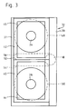
- the front wall shown in Fig. 2 comprises a fixed wall portion 30 and a door assembly 32.
- Door assembly 32 is hinged (by means not shown in Fig. 2) to the fixed wall portion 30 for swinging about a vertical axis adjacent the left-hand side of the assembly as viewed in Fig. 2.
- Fig. 2 The general layout of the major operating elements in the operating region has also been indicated diagrammatically in Fig. 2.
- the outline of the friction roll is indicated at 18
- the outlines of the chucks 24 and 26 in their respective doffing positions are indicated by the appropriate reference numerals and the outline of the traverse mechanism is indicated at 22.
- the path of a thread entering the winding machine from above and extending as far as its first contact with the friction roll 18 is indicated at 28.
- Slot 34 is provided in the top wall 12 in order to permit the thread to enter the machine. Slot 34 is elongated and extends parallel to the longitudinal axis (not indicated) of roll 18. Slot 34 extends forwardly to the front edge of plate 12, for a purpose which will be described immediately below. It extends rearwardly from the front edge over a distance sufficient to permit the normal traversing movement of the or each thread delivered to the winding machine. Plate 12 has a second slot 33 extending from the front edge of the plate rearwardly parallel to slot 34. Slot 33 is normally covered by cover plate 35 which is pivotable about a hinge (not indicated) at its left hand edge. Plate 35 is pivoted away from plate 12, to expose slot 35 from above, only during a threading and start-up operation as referred to briefly below.
- Door assembly 32 extends from its hinged left hand side across the front wall 20 to a right hand edge located to the right of slot 34.
- the door extends upwardly to the top edge of plate 12. Accordingly, when assembly 32 is swung open about its hinge, access is provided to almost the whole of the operating region including in particular the front, open edge of slot 34 and the thread path 28 to the friction roll 18, and beyond that roll upwards to the slot 33, which has been opened by pivoting of the cover 35 away from plate 12.
- the length of thread between friction roll 18 and slot 33 is available for a start-up operation winding thread initially on chuck 26 as in the prior application. This operation is not relevant to the present invention and will not be described in detail.
- the start-up operation can be effected automatically once the thread has been suitably located in the start-up postion. Initiation of the start-up operation can be triggered by pressing of a button on a control panel 36 built into the fixed wall portion 30.
- Door assembly 32 includes a frame 38 which holds two movable doors 40, 42 respectively as will be described below with reference to Figs. 3 to 5 inclusive.
- Each door 40, 42 comprises a respective transparent sheet 44, 46 enabling observation of the operating region, in particular the doffing positions of the chucks.
- Fig. 3 again shows a front elevation of the frame 38 and doors 40, 42. Also, the outlines of two full packages 48, 50 upon the upper and lower chucks 24, 26 respectively have also been shown in Fig. 3; normally, the winder will not carry two full packages in this way, but the condition enables explanation of the relationship between the doors and the full packages during doffing.
- Fig. 3 The full line illustration in Fig. 3 represents the doors in their closed positions. As viewed from the front of the machine (Fig. 3) the door 40 occupies completely the lower half of the space defined within frame 38, and door 42 occupies completely the upper half of that space. As best seen from Fig. 4, however, door 40 is located in front of door 42. Thus, door 40 can be moved into the upper half of frame 38, and door 42 into the lower half of the frame, without causing interference of the doors. The arrangements for causing and guiding such movement will be described later. As viewed in Fig. 3, there is only a very small degree of overlap of doors 40 and 42 at the mid-height of frame 38. Horizontal line 52 represents the upper edge of door 40 and dotted line 53 represents the lower edge of door 42.
- doors 40 and 42 are never moved simultaneously, but only individually.
- Door 40 is raised to enable doffing of a full package 50 from the chuck 26, and door 42 is lowered to enable doffing of a full package 48 from the chuck 24.
- door 40 When door 40 is fully raised, its lower edge lies along the dotted line 54, that is just above the uppermost edge of full package 50 as viewed from the front of the machine.
- door 42 when door 42 is fully lowered, its upper edge lies along the dotted line 56, that is just below the lowermost edge of the full package 46.
- Fig. 4 shows a sectioned plan view of the frame 38 with the central portion thereof omitted so that the more significant side members of the frame can be illustrated to a larger scale.
- Fig. 5 shows in front elevation (corresponding to Fig. 3) the lower corners of the frame 38 drawn to a scale corresponding to that of Fig. 4.
- the left hand side member 37 of the frame 38 is U shaped in section, with the open side of the U-facing inwardly of the frame.
- the right hand member 39 is also U shaped, with its open side facing inwardly of the frame, but the legs of the U are elongated to enable this member to contain additional elements as will be described.
- the doors 40 and 42 are located with their left hand edges just within the arms of U-member 37 and their right hand edges just within the arms of U-member 39.
- Door 40 has a pair of vertical, parallel bores (not indicated) each extending from the top to the bottom edge thereof. By means of these bores, the door is slidably mounted on a pair of parallel guide rods 60 extending between the upper and lower horizontal members of the frame 38. For purposes of accurate and low-friction guidance of the door relative to its guide rods 60, each bore is widened at each end thereof to receive a bearing sleeve 62 which fits accurately on its corresponding guide rod.
- the door is thus accurately located relative to the rods 62 at each corner, although only the bearing sleeves 62 for the lowermost corners are seen in Fig. 5.
- the mounting and guidance of door 42 is substantially the same, and will not be described again in detail.
- the guide rods for door 42 are indicated at 64 in Fig. 4 and the lower bearing sleeves for door 42 are indicated at 66 in the same Figure.
- Each door is moved relative to the frame 38 by a respective piston and cylinder unit, the two units being located side by side within U-member 39.
- the cylinder of the unit operating door 40 is indicated at 68 in Fig. 4 and the cylinder of the unit operating door 42 is indicated at 70.
- Cylinder 68 is fixed at its upper end (not shown) to the upper end of member 39, preferably by a pivotal connection enabling at least limited pivotal movement of the cylinder on its fixing. Cylinder 68 extends approximately halfway down member 39 from its fixing.
- the piston (not shown) of this unit is connected to a connector rod 72.
- the arrangement of the piston and cylinder unit operating door 42 is analogous to that already described for door 40, and the details will therefore be omitted.
- the arrangement is, however, inverted relative to that for door 40. That is, cylinder 70 is fixed to member 39 adjacent the lower end of said member and extends upwardly approximately halfway along member 39.
- the connector rod 80 (Fig. 4) for door 42 is fully extended, its free end is located adjacent the upper end of member 39, and the fitting between the connector rod and the door 42 is secured to the upper corner of that door. Accordingly, when the piston and cylinder unit operating door 42 is retracted, this door moves downwardly along its guide rods 64.
- This mechanism is indicated generally at 82 in Fig. 4. It comprises a latching element 84 which can be moved out of a withdrawn position (not shown) into an extended position (illustrated in Fig. 5) in which it engages with a suitable cooperating member on the fixed wall portion 32. Since this arrangement, and the manual operating means also included in the latching mechanism 82 is of generally conventional construction, it will not be described in detail.
- Fig. 6 is a circuit diagram of a control system for operating the door assembly shown in Fig. 2 to 5.
- the doors 40, 42 are shown again in association with their respective operating cylinders 68, 70 and connecting rods 72, 80.
- the frame 38 is represented separately in this diagram (in the center portion thereof) for reasons which will become apparent from the following description.
- the frame is again assumed to be pivotable about its left-hand edge as viewed in the figure.
- Chucks 24, 26 are indicated on the right-hand side of Figure 6, each being assumed to be in contact with its respective brake-shoe carried by the support elements 198, 200 respectively (that is, each chuck is assumed to be in its respective doffing position).
- the machine as a whole is controlled by a programmable controller represented in Fig. 6 by the block PC.
- a programmable controller represented in Fig. 6 by the block PC.
- This can be in the form of a microprocessor, but many other forms of such controllers are now currently available, so that details of such controllers will not be provided here.
- the controller is adapted to receive pretedermined input signals, and to emit predetermined output signals for control purposes in dependence upon the sequence and/or combination of input signals received.
- the controller will be designed to control a very large number of functions in the machine, and will have many more inputs and outputs than those referrred to here.
- the present description is confined to those inputs and outputs concerned with control of the door system.
- the arrangement for controlling individual door 42 is substantially identical with that for control of door 40. Accordingly, only the operation of the latter will be described although the control elements used for control of the former will also be referred to.
- Cylinder 68 is a double acting cylinder having chambers which can be pressurized via lines 82, 84 respectively.
- Line 82 is connected to the output from an element 86 which will be further described below.
- Line 84 is connected to a lead 88 which extends between a valve 90, further described below, and one input to the element 86.
- Another input to element 86 is connected to a source of pressure diagrammatically indicated at 92 and the same or another source of pressure can provide the pressure input to valve 90 indicated at 94.
- Valve 90 is biased to the illustrated condition in which lead 88 is isolated from the pressure source 94.
- An operating mechanism 96 (for example, an electro-magnetic device) is provided to operate valve 90 against the bias in order to place lead 88 in communication with pressure source 94.
- Mechanism 96 is selectively operable by the programmable controller PC on a control lead 98.
- Element 86 is so arranged that line 82 is in communication with pressure source 92 in the illustrated condition in which lead 88 is isolated from pressure source 94. In this condition, therefore, the upper chamber of cylinder 68 is pressurized from the source 92, the piston of the unit is moved to its lowermost position in the cylinder, door 40 is held in its lower position and therefore blocks access to the doffing position of chuck 26.
- Element 86 reacts to pressurization of lead 88 by isolating line 82 from pressure source 92 and connecting lead 82 to a suitable vent. The piston is therefore moved upwardly along cylinder 68, drawing door 40 upwardly along its guide rods 60 as described with reference to Figs. 4 and 5. Access is therefore provided to the doffing position of chuck 26 as described with reference to Fig. 3. Element 86 therefore functions as a NOT-element, for example of the type supplied by Crouzet SA, F 26027 Valences, France under the designation Type 81 504025.
- the signal supplied by controller PC to operating mechanism 96 in order to cause the described operation of valve 90 is produced by the controller in response to input signals it receives from two signal generators 100, 102 respectively.
- Generator 100 responses simply to the presence of chuck 26 in its doffing position.
- This generator may be, for example, a proximity sensor adapted to respond to the presence of a part of the chuck structure in the neighbourhood of the sensor.
- Generator 102 is designed to respond to rotation of the chuck 26.
- this generator is assumed to be a pulse generator adapted to generate pulse signals when it is passed by markings 104 on the circumference of the chuck 26 when the latter is rotating. When rotation of chuck 26 ceases, and the markings 104 no longer pass by the generator 102, generation of pulses ceases.
- controller PC When controller PC receives a signal from sensor 100 indicating that chuck 26 is in its doffing position, and at the same time does not receive a pulse sequence from generator 102, the controller emits a signal on line 98 causing operation of mechanism 96. The mechanism operating signal will not, however, appear on line 98 until any pulse sequence issued by generator 102 has ceased, that is, door 40 continues to block access to the doffing position of chuck 26 until the latter has come to a standstill.
- Controller PC also controls operation of a locking mechanism for the complete door assembly 32 (Fig. 2).
- This locking mechanism which is additional to the previously described latching mechanism, comprises an additional piston and cylinder unit 104 (Fig. 6, also indicated on Fig. 2), the cylinder of which is fixedly secured to the fixed wall portion 30.
- the piston of unit 104 is secured to a locking pin 106 (Fig. 6) and when unit 104 is extended pin 106 can enter a suitable recess (not indicated) provided in the right-hand edge of frame 38 when door assembly 32 is in its closed position.
- Unit 104 is single acting, being normally biased to its extended (locking) condition. Pin 106 can be retracted when the left-hand chamber (as viewed in Fig.
- valve 108 in the cylinder of unit 104 is pressurized by operation of a valve 108 similar to valve 90.
- An operating mechanism 110 is provided, similar to the mechanism 96 and correspondingly controllable by signal from controller PC along a lead 112.
- a suitable sensor 114 for example a proximity sensor, responds to the presense of door 32 in the closed condition and provides a corresponding input signal to controller PC on line 116.
- buttons indicated on control panel 36 in Fig. 2 may be marked respectively as “thread-up” and “start” buttons. Controller PC also responds to the conditions of these buttons.
- controller PC checks the condition of each of generators 100, 100A, 102, 102A.
- a "release" signal on line 112 causing operation of valve 108 to withdraw pin 106 will be produced only if both chucks 24, 26 are in their respective doffing positions and are not rotating. Failing this, a fault signal will be issued. If required conditions are satisfied, pin 106 is withdrawn to enable opening of a door assembly 32 and threading-up as already described with reference to Fig. 2.
- the side walls and top wall of the enclosure may each comprise a structural element, for example a relatively thin metal sheet, and a covering element designed to absorb or otherwise damp noise emission from the enclosure.
- a structural element for example a relatively thin metal sheet
- a covering element designed to absorb or otherwise damp noise emission from the enclosure.
- the central zone between the two doffing positions cannot be exposed for access to the operating region by operation of the doffing doors 40, 42, but only by opening of the complete door assembly.
- This central region contains the friction roll and also the complete locus of movement of thread packages during winding operations on both the upper and lower chucks.
- Each doffing door 40, 42 provides free access only to its own associated doffing position, and not to an ongoing winding operation on the other chuck. If required, the central region could be blocked in by structure fixed relative to the complete door assembly, and the doffing doors 40, 42 could then be made correspondingly smaller.
- sealing arrangements in the central region may then become relatively complex, and it is preferred to provide overlapping doors 40, 42 (generally as in Fig. 2). Suitable sealing (not illustrated) can be provided between the overlapped doffing doors.
- machines as illustrated are frequently arranged side-by-side in an array or battery.
- the minimum possible spacing is usually provided between the adjacent side walls.
- the side walls for intermediate machines in the array that is those not at the exterior of the array, could be omitted provided adequate structure remains to support the front walls thereof.
- this is not the preferred arrangement. Instead, it is preferred to provide side walls even in the array, so that each winding machine forms an isolated unit. This minimizes the risk that faults in one unit can cause associated faults in an adjacent unit, and it also improves safety since access to the operating region of one unit provides no access whatsoever to the operating region of any other unit.
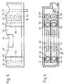
- FIG. 7 An alternative arrangement is shown in Fig. 7 where the modified front wall of the winder is indicated as a whole by reference numeral 20A.
- the outlines of the friction roll 18 and chucks 24, 26 are indicated in dotted lines, and these elements are identical with those shown in the previous embodiment.
- Doors 40A and 42A are essentially the same as the similarly numbered elements shown in Fig. 2.
- Line 52 represents the upper edge of lower door 40A; the lower edge of upper door 42A is hidden due to the overlap.
- the fixed wall portion 130 now provides the support structure for doors 40A, 42A.
- an additional door 121 is provided in the right-hand, upper portion of the front wall, being hinged at its right-hand vertical edge (as viewed in Fig. 7) to enable the right-hand upper portion of the operating region to be exposed.
- Door 121 extends downwardly to a position slightly below the lowermost point on roll 18. Control panel 36 is built into door 121.
- Door 121 is opened for threading up of the machine and it then exposes the front edge of top plate 12 of the enclosure and of the slot 34 which is identical in arrangement and function to slot 34 in Fig. 2.
- the thread path 28 as far as friction roll 18 is therefore the same in Figs. 2 and 7.
- the thread path downstream from friction roll 18 does not extend upwardly from roller 18 as in Fig. 2, but stubstantially horizontally across the upper part of door 40A as indicated by line 128 in Fig. 7. This portion of the thread path extends to a guide diagrammatically illustrated at 122 adjacent the left-hand side of door 40A.
- Door 40A must therefore be maintained open throughout the threading up operation to enable access to guide 122 so that thread path 128 can be established.
- the lowermost edge of door 121 must also extend at least slightly below the lower edge of door 40A when the latter is its raised position.
- the thread is drawn forwardly out of the operating region through the access opening associated with door 40A.
- chuck 24 is moved downwardly into winding association with roll 18, thereby taking up the thread along path length 128.
- door 40A must be maintained open until take up of the thread by chuck 24, or door 40A must be provided with an openable and closeable sub-section along its left-hand edge, the sub-section being opened to enable the thread to be drawn out of the machine even with door 40A in its closed position during the start-up operation.
- Doors 40A, 42A can be guided by guide rods which on the left-hand side as viewed in Fig. 7 are identical with those described with reference to Fig. 4. Similar operating piston and cylinder units can be provided, being associated however with the left-hand sides of the doors in Fig. 7 instead of the right as in Fig. 4. The guide rods on the right-hand side must be discontinuous to enable the thread to be passed into the operating region from the front of the machine.
- Fig. 8 illustrates the application of the principles of this inventions to an alternative type of continuous or wasteless winder.
- the friction roll is indicated at 180, one chuck at 124 and the other at 126; the traverse mechanism has been omitted, but is substantially the same as that shown in the preceding figures.
- chucks 124, 126 are carried on a common support ("revolver head") 132 which is rotatable about a central axis 134 extending parallel to the chuck axes (not shown).
- revolver head common support
- chuck 124 has just been brought into winding association with the friction roll 18, while chuck 126 has been moved to a doffing position, and carries a full package the outline of which is indicated at 136. While package winding continues on chuck 124, the full package (can be removed from chuck 126 and replaced by one or more fresh bobbin tubes ready for the next winding operation on that chuck.
- revolver head 132 is rotated about axis 134 to bring chuck 124 into the doffing position and to move chuck 126 into association with roll 180.
- transfer means (not shown) are effective to ensure that the thread is transferred from the outgoing to the incoming chuck.
- revolver head 132 may be fixed in a specific angular disposition about its axis 134 during any one winding operation, and friction roll 180 may be moved relative thereto, for example by vertical movement along the double-headed arrow 138 indicated in dotted lines in Fig. 8.
- roll 18 may be disposed in a fixed position relative to the machine frame and revolver head 132 may be rotatable about its axis 134, for example as illustrated by the dotted line arrow 139, in order to enable package build up.
- a circular access opening can be defined of a dimension slightly greater than the outline 136 and centered upon the axis of chuck 126 (or 124) in the doffing position.
- This can be normally closed by a door 140 pivoted at 141 for rotation relative to wall 120 about an axis extending parallel to the chuck axes, for example as indicated by the arrow 143. Opening of this door enables access to the doffing position for both chucks.
- a suitable locking means (not shown) similar to locking means 104 (Fig.
- the whole of the front wall 120 may be hinged at the left-hand vertical edge (as viewed in Fig. 8) to enable threading up of the machine and suitable inlet openings must be provided for the threads during normal operation and suitable exit openings for the threads during threading up.
- the doffing door In the arrangement in which revolver head 132 rotates during a winding operation, the doffing door must be made somewhat larger, since the doffing position wanders during an ongoing winding operation.
- This larger door might be made vertically slideable on the wall 120, so as to be raisable from the lower into the upper half of that wall.
- the door is dimensioned to hinder access to the ongoing winding operation at all stages thereof.
- the invention is not limited to the illustrated type of doors.
- slider doors for example, foldable doors could be used, or flexible, rollable doors could be provided.
- slat-type doors of the type shown in US Patent 3146572 could be used.
- control system indicated in Fig. 6 is diagrammatic only to indicate the principles involved; modification to the system can be made as required.
- alternative means may be used to generate a signal or a combination of signals indicating that a chuck is in a required condition.
- arrangements are already known in accordance with which the braking force between the chuck and a brake-shoe is sensed, so that the package clamping means in the chuck is released only when the brake-force sensor indicates that the chuck has been braked to a standstill.
- This arrangement could be used to produce an appropriate signal for control of the doffing doors. With the aid of additional complication, the arrangement could be such that the door is permitted to open when the rotational speed of the chuck has dropped below a predetermined set value.
- a control system may be a central control system for a complete installation including a battery of winding machines together with the package transporting carriage.
- a control system may be a control system on the carriage. In either case, the control system will need to "know" when the appropriate doffing door on the winder has been opened.
- additional signal generators and signal leads are required in the arrangement of Fig. 6.
- the additional signal generators must be arranged to respond to the positions of the associated doff doors 40, 42, at least when those doors are in the open positions.
- the signal generators may include contact or non-contact position/proximity sensors.
- each door may carry a "marker" or "flag" on one side edge, for example near the upper or lower edge, and this may be aligned with a marker/flag sensor on the frame elements 37 or 39 when the door is open.
- the sensors may be of the magnetic type, or photoelectric type.
- the marker is located near the upper door edge.
- sub-assembly (within frame 38) should not be connected directly to the machine structure, but instead this sub-assembly should be pivotally secured to at least one support element and the latter should be releasably secured to the machine frame.
- Figure 9 is a view similar to Figure 4 (but showing only the left-hand door edge of Fig. 4) with the addition of the auxiliary support element.
- auxiliary support in the form of an elongated channel element 150, extending over the full height of the left hand, front edge portion 152 of the machine frame.
- element 150 carries forwardly projecting lugs (only the lower lug 154 is visible in Fig. 9).
- Pivot pins extend between frame 38 and the lugs on element 154, only the lower pin 156 being visible in Fig.9.
- Frame 38 is pivotable on these pins between its open and closed positions relative to the frame.
- Channel element 150 opens onto the interior of the machine enclosure.
- the rear side wall of the channel engages the frame portion 152 and is releasably secured thereto, for example by bolts such as bolt 158.
- the front side wall of the channel engages the frame element 37 when the frame 38 is in its closed position (as illustrated).
- L-shaped projections such as projection 160, on frame element 37 then engage behind the front wall of the channel and ensure that the door remains shut at the hinge even in the event of an accident within the enclosure.
- a duct 162 indicated in dotted lines in Fig. 10, which is a view similar to Fig. 2.
- This duct is arranged with an equal spacing from each of the rest positions of the chucks to avoid interference with package build or with package storage in the rest postions of the chucks 24, 26.
- Quick release connectors (not shown) are provided between leads (not shown) in the sub-assembly and corresponding leads (not shown) in the duct 162. These connectors are provided at predetermined positions on the end face of duct 162 and on the corresponding mating face of channel element 150, and may be manually or automatically engaged when the channel element is correctly located on the support frame.
- Fig. 10 shows further detail of an additional feature already mentioned above, namely the conditioning system for the interior of the enclosure.
- Ducts 164, 166, 168 and 170 are formed in the corners of the operating region. These ducts occupy the free space left around packages on chucks 24, 26, in the rest positions, without of course interfering with chuck movement.
- Each duct 164 to 170 extends from the front face of the machine rearwards through the operating region to the headstock. Spaced along the length of each duct is a set of ports enabling air flow between the operating region and the interior of the duct.
- the lower ducts 164 and 166 are arranged as cool air inflow ducts. They may be connected together (not shown) within the head stock to cool air infeed from a seperate source associated with the complete installation, for example an air conditioning system for the plant.
- the upper ducts 168, 170 are arranged as warm air exit ducts. They may also be connected together (not shown) within the headstock and thereby linked into an overall air conditioning system. Alternatively, of course, the machine may be provided with its own fan, and the air infeed may draw air from the workroom surrounding the machine, in which case filters may be provided in the air flow system within the machine.
Landscapes
- Engineering & Computer Science (AREA)
- Textile Engineering (AREA)
- Replacing, Conveying, And Pick-Finding For Filamentary Materials (AREA)
- Spinning Or Twisting Of Yarns (AREA)
Description
- The present invention relates to improvements in enclosures for the operating regions of high-speed winding machines, for example take-up winders for threads of synthetic filament. In this context, the term "high-speed" refers generally to speeds in excess of 2000 m/min, but especially to speeds in excess of 4000 m/min.
- Enclosure of the main drives and ancillary service parts of textile machines has of course been common practice since the inception of such machines. Enclosure of the "operating regions" of those machines, for example the regions in which thread is spun and/or wound, is much less common, but has been proposed for a number of different purposes. For example, in United States Patent 3146572, it is proposed that raisable and lowerable shutters should be used to define an enclosed space containing the machine, which space can be controllably climatised in use. The shutters can be raised and/or lowered in order to provide access to the relevant operating regions when required. The arrangement has not found wide acceptance in the industry.
- United States Patent 3782087 describes a twisting machine in which selected regions of the machine, especially the spindle assemblies, are selectively shielded to control noise emission. Raisable and lowerable shutters are again shown in Figs. 10 to 16 of this patent.
- US Patent 3274803 describes a knitting machine in which the actual knitting region is enclosed to protect it from dust penetration, the enclosure including horizontally slidable transparent doors enabling selective access to the knitting region.
- Surprisingly, the idea of enclosing the operating region of the machine has been extended only comparatively recently to the enclosure of the operating region of take-up winders for example for threads of synthetic filament.
- US 2971710 shwos a wire winder having a safety slider plate slidable from side to side of the winder assembly in front of the winding heads. A winding head cannot be energised unless the plate is in a position which partly blocks access to the relevant winder head from the front thereof.
- A recent proposal for such enclosure is, however, shown in the European Patent Application published under the number 141936 on 26th May 1985, corresponding with United States
Patent Application 06/649222 filed on 10th September 1984 in the name Kurt Wetter. In that proposal, an access door extends over the whole of the front face of the winder, and is movable to the side thereof when access is required to the operating region for example for threading up or doffing of packages. The proposal is intended especially to limit noise emission from the winder. - The present invention provides a thread winding machine with enclosure. One function of the enclosure is to limit or control noise emission from the operating region of the winder. A second, and possibly more important function is to improve safety in operation by enabling only predetermined access to the operating region.
- This is to be contrasted with many of the arrangements of the prior art, in which it is an aim of the design to enable as far as possible unhindered access to the operating region for the performance of service operations.
- In a subsidiary feature of the invention, the above-mentioned functions are to be enabled in a layout which is economical in space. This is frequently very significant, for example when space is at a premium in layout of a complete installation comprising a large number of take-up winders located in a "battery".
- The invention provides a machine for winding thread comprising an operating region in which thread packages are formed and retained, if necessary, to await doffing thereof. In the operating region, there is at least one chuck rotatable about a longitudinal chuck axis for winding of thread into a package thereon. The chuck has a pretedermined doffing position in the operating region; the chuck is located in this position during removal of completed thread packages therefrom.
- The invention is characterised in that an enclosure is provided and comprises at least one access door openable to enable access to the doffing position of said chuck and controllably releasable retaining means is provided for the door. The retaining means is operable to retain the door in a condition closing the enclosure and to release the door to permit opening thereof to provide access to said chuck for removal of a completed package therefrom. There is also a sensing means responsive to the rotational condition of the chuck in its doffing position, and control means responsive to the sensing means and operable to control the retaining means. The arrangement is such that the door cannot be released unless the chuck is in a predetermined condition, for example located in its doffing position and at a standstill.
- The invention is intended particularly, but not exclusively, for application to a winder in which at least two chucks are provided in the operating region, each chuck being rotatable about its respective longitudinal chuck axis and being operable to wind packages sequentially to enable virtually continuous winding of thread. The operating region may contain other operating elements for cooperation with the chuck or with a thread during package winding, for example a friction drive roller for contacting the circumference of a package during winding thereof and/or a traverse mechanism for traversing a thread longitudinally of the chuck axis during package winding.
- According to further features of the invention, the control means may also be operable to control a drive means for driving the chuck. A sensor means is provided responsive to the condition of the door, and the control means is responsive to the sensor means so that the chuck drive means cannot be energised unless the door is in a predetermined condition, for example closed.
- In the preferred embodiments of all aspects of the invention, the enclosure comprises a "front wall" through which selected access to the operating region is to be enabled. The enclosure preferably comprises continuous side walls which do not enable access to the operating region when they are in place. A top wall of the enclosure may be either continuous, preventing access to the operating region, or may have very limited access openings for certain specific functions, for example in threading up. The rear of the operating region preferably adjoins a head stock and the operating region enclosure then preferably merges into a head stock enclosure. The enclosure may comprise a bottom plate, but this may be omitted where the machine is designed to stand upon an adequate base, for example a floor. The remaining walls of the enclosure can then form a hood closely approaching this base at its lowermost edges.
- By way of example, several embodiments of the invention will now be described with reference to the accompanying diagrammatic drawings, in which.
- Fig. 1 is a perspective view of a winding machine already commercially available from Rieter Machine Works Ltd. and in accordance with the European Patent Application published under the number 73930,
- Fig. 2 is the front elevation of a machine basically similar to that shown in Fig. 1 but modified to include an enclosure according to the present invention,
- Fig. 3 is a front elevation of a door assembly also shown in Fig. 2 but drawn to a larger scale in Fig. 3,
- Fig. 4 is a sectioned plan view of the door assembly shown in Fig. 3, the central portion thereof being omitted to enable illustration of the side elements to still larger scale,
- Fig. 5 is a front elevation of the lowermost corners of the door assembly,
- Fig. 6 is a diagrammatic representation of the door assembly in association with an operating system therefor,
- Fig. 7 is a view similar to Fig. 2 of an alternative embodiment of front wall for the enclosure of a machine of the type shown in Fig. 1,
- Fig. 8 is a front elevation of a type of winding machine different from that shown in Fig. 1 but also including an enclosure in accordance with the principles of the present invention, and
- Figs. 9 and 10 illustrate modifications of the previously described embodiments.
- Take-up winders for synthetic platics filament are currently available in two basic types, namely
- a) a multi-chuck winder with means for transferring a continuously delivered thread from one chuck to another so as to enable substantially continuous or "wasteless" package winding, and
- b) single chuck or multi-chuck winders without such transfer arrangements, so that package winding must be terminated during removal of completed packages.
- The present invention is intended particularly, but not exclusively, for application to the former type of winder where safety aspects are especially important during doffing (removal) of completed filament packages from one chuck during an ongoing winding operation on the other chuck. One design of continuous winder is shown in European Patent Application No. 73930, which is hereinafter referred to as "the prior application". The invention can be applied to alternative designs of continuous winder, for example the so-called "revolver" type, an example of which is illustrated in United States Patent 4298171. Still further possibilities will be referred to towards the end of the description, including the application of the principles of the invention to single-chuck type winders, for example as illustrated in United States Patent No. 4347989.
- Fig. 1 is a copy of Fig. 8 of European Published Patent Application No. 73930, but certain reference numerals have been changed to avoid conflict of usage with reference numerals used in other Figures of this application. Since full details of the machine are available from the published European Patent Specification, only a very brief outline will be repeated in this specification.
-
Numeral 16 indicates a head stock housing containing drive systems, control systems and supports for the major operating elements which project forwardly from the front face of the head stock housing. Only some of those systems and supports have been shown in Fig. 1. - In Fig. 1, the front face of the
head stock housing 16 is represented by a plate 310 havingslots Slots friction drive roll 18 extending forrwardly from plate 310.Roll 18 is supported at one end (by means not shown) in thehead stock housing 16, and at the other end in asupport structure 300 which projects cantilever-fashion from the front face of the housing. Driveroll 18 can be driven into rotation about its longitudinal axis (not shown) by means of adrive shaft 316 extending into thehousing 16 to a non-illustrated (conventional) drive means therein. - Two further major operating elements illustrated in Fig. 1 are the
chucks housing 16 so as to project cantilever-fashion throughrespective slots drive roll 18, as illustrated in Fig. 1) and a position in which thetubes 302 are brought into contact withrespective drive regions 304 formed on thedrive roll 18. - In use, the chucks are brought alternately into the winding condition, that is into winding contact with the
drive roll 18. While one chuck is in the winding condition, the other is maintained in its doffing position. When formation of thread packages on the one chuck is completed a changeover operation is effected so that the threads are transferred from the one chuck to the other as the latter is moved into its winding condition. Details of the changeover operation are provided in European Patent Application No. 73930. The chuck bearing the completed packages (the "outgoing" chuck) is returned to its doffing position while winding of thread continues on the other chuck. When rotation of the chuck in the doffing position has ceased, release mechanisms (not shown) within the chuck structure release the packages formed thereon, and these can be pushed off the chuck on command by the appropriate one of a pair of push-outshoes 118 associated with the respective doffing positions. An operating shaft for reciprocating thelower shoe 118 longitudinally of itsrespective chuck 26 is indicated at 120, and a similar operating shaft is provided for the upper shoe. - For completion of description of the major operating elements forward of the plate 310, it is mentioned that a conventional traverse mechanism also projects forwardly from that plate, but in Fig. 1 this mechanism is hidden behind the
support structure 300. The threads delivered to thechucks structure 300, between the traverse mechanism and that structure, around driveroll 18 and into their respective packages. Twobobbin tubes 302 have been illustrated in Fig. 2 merely by way of example. In practice, only one package may be formed per chuck, or there may be more than two packages (commonly up to 8) per chuck. For ease of description, in the remainder of this specification only a single thread will be referred to. It will be understood, however, that all operations described for this thread apply equally to any other threads wound simultaneously. - As more fully described in European Patent Application No. 73930, each
chuck housing 16.Chuck 24 is secured to its swing-arm by a set of clampingjaws 354, and a similar set of jaws (but without reference numeral) is illustrated forchuck 26. The swing-arm bearing chuck 24 can be moved through a defined swing-angle (sufficient to move the chuck from its doffing position into the winding condition) by a piston and cylinder assembly, the cylinder of which is seen at 358 and the non-illustrated piston of which is connected to the swing-arm by connectingrod 360. The swing-arm bearing chuck 26 is operated by a similar piston and cylinder assembly, only the cylinder which can be seen at 212. - The main structural elements of
housing 16 include abase plate 328 and anupper plate 334 parallel to the base plate.Cylinder 358 is pivotally secured to aboss 210 onbase plate 328, andcylinder 212 is pivotally secured to aboss 214 mounted on the underside ofplate 334.Numeral 198 indicates a support element secured to plate 334 and carrying a brake-shoe (not shown) for braking rotation ofchuck 24 after the latter returns to its doffing position upon completion of a winding operation. Asimilar support element 200 is mounted onbase plate 328 for association withchuck 26. -
Numeral 135 illustrates a bracing strut in thehousing 16, and other vertical structural elements are provided in that housing as already described in the prior application. Numerals 306 and 308 respectively indicate locations at which thread catching and severing devices are provided onchuck 26. Since these devices are of a known type, and form no part of the present invention, they will not be referred to again in this specification. Thearm 324, with itsrollers 122, indicated at the upper right in Fig. 1 was used for threading of the machine as described in the prior application; the embodiment to be described with reference to Figs. 2 to 7 includes an alternative threading system, so thatarm 324 will not be referred to again in this specification. - European Application No. 73930 refers to a "operating region" in front of
plate 110. Although the operating region was not precisely defined in the prior application, it can be considered to comprise the space forward of the plate 310 at least as far as the end ofstructure 300, that is the region containing the major movable parts operating on the thread in each winding operation. In the machine shown in Fig. 1, ahood 326 was provided over the operating region. As will now be described, the present invention provides an enclosure for this region, with a corresponding substantial improvement in safety and in environmental conditions in the neighbourhood of the winder. The modifications to be described refer only to the enclosure of the operating region of the winder. The major operating elements remain substantially unchanged except for the mounting ofroll 18. In the embodiment to be described, thesupport structure 300 is eliminated, and roll 18 is supported cantilever-fashion withinhousing 16. Since this arrangement is in any event conventional, it will not be described in detail. - The modifications to be described enable total enclosure of the operating region. Basically, this requires the design of a casing around that region. Only the front wall of this casing is of special significance in relation to the present invention. The remainder of the casing is provided simply by extending the
base plate 328,top plate 314 and side plates (not shown) of thehousing 16 forwardly of the plate 310. In Fig. 2, the forward extension of the base plate is indicated at 10, that of the top plate at 12, and the forward extension of the side plates are indicated at 14. - The front wall shown in Fig. 2 comprises a fixed
wall portion 30 and adoor assembly 32.Door assembly 32 is hinged (by means not shown in Fig. 2) to the fixedwall portion 30 for swinging about a vertical axis adjacent the left-hand side of the assembly as viewed in Fig. 2. - The general layout of the major operating elements in the operating region has also been indicated diagrammatically in Fig. 2. Thus, the outline of the friction roll is indicated at 18, the outlines of the
chucks friction roll 18 is indicated at 28. -
Slot 34 is provided in thetop wall 12 in order to permit the thread to enter the machine.Slot 34 is elongated and extends parallel to the longitudinal axis (not indicated) ofroll 18.Slot 34 extends forwardly to the front edge ofplate 12, for a purpose which will be described immediately below. It extends rearwardly from the front edge over a distance sufficient to permit the normal traversing movement of the or each thread delivered to the winding machine.Plate 12 has asecond slot 33 extending from the front edge of the plate rearwardly parallel to slot 34.Slot 33 is normally covered bycover plate 35 which is pivotable about a hinge (not indicated) at its left hand edge.Plate 35 is pivoted away fromplate 12, to exposeslot 35 from above, only during a threading and start-up operation as referred to briefly below. -
Door assembly 32 extends from its hinged left hand side across thefront wall 20 to a right hand edge located to the right ofslot 34. The door extends upwardly to the top edge ofplate 12. Accordingly, whenassembly 32 is swung open about its hinge, access is provided to almost the whole of the operating region including in particular the front, open edge ofslot 34 and thethread path 28 to thefriction roll 18, and beyond that roll upwards to theslot 33, which has been opened by pivoting of thecover 35 away fromplate 12. The length of thread betweenfriction roll 18 andslot 33 is available for a start-up operation winding thread initially onchuck 26 as in the prior application. This operation is not relevant to the present invention and will not be described in detail. The start-up operation can be effected automatically once the thread has been suitably located in the start-up postion. Initiation of the start-up operation can be triggered by pressing of a button on acontrol panel 36 built into the fixedwall portion 30. -
Door assembly 32 includes aframe 38 which holds twomovable doors door transparent sheet - Fig. 3 again shows a front elevation of the
frame 38 anddoors full packages lower chucks - The full line illustration in Fig. 3 represents the doors in their closed positions. As viewed from the front of the machine (Fig. 3) the
door 40 occupies completely the lower half of the space defined withinframe 38, anddoor 42 occupies completely the upper half of that space. As best seen from Fig. 4, however,door 40 is located in front ofdoor 42. Thus,door 40 can be moved into the upper half offrame 38, anddoor 42 into the lower half of the frame, without causing interference of the doors. The arrangements for causing and guiding such movement will be described later. As viewed in Fig. 3, there is only a very small degree of overlap ofdoors frame 38.Horizontal line 52 represents the upper edge ofdoor 40 and dotted line 53 represents the lower edge ofdoor 42. - As will be described later with reference to the control system diagram in Fig. 6,
doors Door 40 is raised to enable doffing of afull package 50 from thechuck 26, anddoor 42 is lowered to enable doffing of afull package 48 from thechuck 24. Whendoor 40 is fully raised, its lower edge lies along the dottedline 54, that is just above the uppermost edge offull package 50 as viewed from the front of the machine. Correspondingly, whendoor 42 is fully lowered, its upper edge lies along the dottedline 56, that is just below the lowermost edge of thefull package 46. Thus, when the appropriate door is opened, a full package in the upper or lower doffing position can be readily removed from the operation region via the access opening created within theframe 38 by movement of the door relative thereto. However, the space within theframe 38 lying between thelines doors friction roll 18 during an ongoing winding operation. Accordingly, there is no direct access to this "danger zone" of the operating region even during doffing a full package. - The mounting of
doors frame 38, the source of motive power for these doors, and the guidance thereof will now be described with reference to Figs. 4 and 5. Fig. 4 shows a sectioned plan view of theframe 38 with the central portion thereof omitted so that the more significant side members of the frame can be illustrated to a larger scale. Fig. 5 shows in front elevation (corresponding to Fig. 3) the lower corners of theframe 38 drawn to a scale corresponding to that of Fig. 4. As viewed in Fig. 4, the lefthand side member 37 of theframe 38 is U shaped in section, with the open side of the U-facing inwardly of the frame. Theright hand member 39 is also U shaped, with its open side facing inwardly of the frame, but the legs of the U are elongated to enable this member to contain additional elements as will be described. - As clearly seen in Fig. 4, the
doors U-member 39.Door 40 has a pair of vertical, parallel bores (not indicated) each extending from the top to the bottom edge thereof. By means of these bores, the door is slidably mounted on a pair ofparallel guide rods 60 extending between the upper and lower horizontal members of theframe 38. For purposes of accurate and low-friction guidance of the door relative to itsguide rods 60, each bore is widened at each end thereof to receive abearing sleeve 62 which fits accurately on its corresponding guide rod. The door is thus accurately located relative to therods 62 at each corner, although only the bearingsleeves 62 for the lowermost corners are seen in Fig. 5. The mounting and guidance ofdoor 42 is substantially the same, and will not be described again in detail. The guide rods fordoor 42 are indicated at 64 in Fig. 4 and the lower bearing sleeves fordoor 42 are indicated at 66 in the same Figure. - Each door is moved relative to the
frame 38 by a respective piston and cylinder unit, the two units being located side by side withinU-member 39. The cylinder of theunit operating door 40 is indicated at 68 in Fig. 4 and the cylinder of theunit operating door 42 is indicated at 70.Cylinder 68 is fixed at its upper end (not shown) to the upper end ofmember 39, preferably by a pivotal connection enabling at least limited pivotal movement of the cylinder on its fixing.Cylinder 68 extends approximately halfway downmember 39 from its fixing. The piston (not shown) of this unit is connected to aconnector rod 72. When the piston and cylinder unit is fully extended, that is when the piston is at the lowermost end ofcylinder 68, the lower end ofrod 62 is adjacent the bottom ofmember 39 and the lower edge of door 40 (as shown in Fig. 5). This free end of the connector rod has a fitting comprising afirst element 74 fixedly secured to the rod, asecond element 76 fixedly secured to the adjacent, lower corner ofdoor 40 and a pivot joint 78 between theelements cylinder 68,door 40 is drawn upwardly alongrods 60 until movement of the piston stops when it reaches the upper end ofcylinder 68. - The arrangement of the piston and cylinder
unit operating door 42 is analogous to that already described fordoor 40, and the details will therefore be omitted. The arrangement is, however, inverted relative to that fordoor 40. That is,cylinder 70 is fixed tomember 39 adjacent the lower end of said member and extends upwardly approximately halfway alongmember 39. When the connector rod 80 (Fig. 4) fordoor 42 is fully extended, its free end is located adjacent the upper end ofmember 39, and the fitting between the connector rod and thedoor 42 is secured to the upper corner of that door. Accordingly, when the piston and cylinderunit operating door 42 is retracted, this door moves downwardly along itsguide rods 64. - For the sake of completeness, brief reference is made here to the door latching mechanism built into the
right hand member 39. This mechanism is indicated generally at 82 in Fig. 4. It comprises a latchingelement 84 which can be moved out of a withdrawn position (not shown) into an extended position (illustrated in Fig. 5) in which it engages with a suitable cooperating member on the fixedwall portion 32. Since this arrangement, and the manual operating means also included in thelatching mechanism 82 is of generally conventional construction, it will not be described in detail. - Fig. 6 is a circuit diagram of a control system for operating the door assembly shown in Fig. 2 to 5. In this diagram, the
doors respective operating cylinders rods frame 38 is represented separately in this diagram (in the center portion thereof) for reasons which will become apparent from the following description. The frame is again assumed to be pivotable about its left-hand edge as viewed in the figure.Chucks support elements - The machine as a whole is controlled by a programmable controller represented in Fig. 6 by the block PC. This can be in the form of a microprocessor, but many other forms of such controllers are now currently available, so that details of such controllers will not be provided here. Essentially, the controller is adapted to receive pretedermined input signals, and to emit predetermined output signals for control purposes in dependence upon the sequence and/or combination of input signals received. The controller will be designed to control a very large number of functions in the machine, and will have many more inputs and outputs than those referrred to here. The present description is confined to those inputs and outputs concerned with control of the door system. The arrangement for controlling
individual door 42 is substantially identical with that for control ofdoor 40. Accordingly, only the operation of the latter will be described although the control elements used for control of the former will also be referred to. -
Cylinder 68 is a double acting cylinder having chambers which can be pressurized vialines Line 82 is connected to the output from anelement 86 which will be further described below.Line 84 is connected to a lead 88 which extends between avalve 90, further described below, and one input to theelement 86. Another input toelement 86 is connected to a source of pressure diagrammatically indicated at 92 and the same or another source of pressure can provide the pressure input tovalve 90 indicated at 94. -
Valve 90 is biased to the illustrated condition in which lead 88 is isolated from thepressure source 94. An operating mechanism 96 (for example, an electro-magnetic device) is provided to operatevalve 90 against the bias in order to placelead 88 in communication withpressure source 94.Mechanism 96 is selectively operable by the programmable controller PC on acontrol lead 98. -
Element 86 is so arranged thatline 82 is in communication with pressure source 92 in the illustrated condition in which lead 88 is isolated frompressure source 94. In this condition, therefore, the upper chamber ofcylinder 68 is pressurized from the source 92, the piston of the unit is moved to its lowermost position in the cylinder,door 40 is held in its lower position and therefore blocks access to the doffing position ofchuck 26. - When
mechanism 96 is operated, however,line 84 is pressurized fromsource 94 and correspondingly pressurizes the lower chamber incylinder 68.Element 86 reacts to pressurization oflead 88 by isolatingline 82 from pressure source 92 and connectinglead 82 to a suitable vent. The piston is therefore moved upwardly alongcylinder 68, drawingdoor 40 upwardly along itsguide rods 60 as described with reference to Figs. 4 and 5. Access is therefore provided to the doffing position ofchuck 26 as described with reference to Fig. 3.Element 86 therefore functions as a NOT-element, for example of the type supplied by Crouzet SA, F 26027 Valences, France under the designation Type 81 504025. - The signal supplied by controller PC to operating
mechanism 96 in order to cause the described operation ofvalve 90 is produced by the controller in response to input signals it receives from twosignal generators Generator 100 responses simply to the presence ofchuck 26 in its doffing position. This generator may be, for example, a proximity sensor adapted to respond to the presence of a part of the chuck structure in the neighbourhood of the sensor.Generator 102 is designed to respond to rotation of thechuck 26. In the illustrated embodiment, this generator is assumed to be a pulse generator adapted to generate pulse signals when it is passed bymarkings 104 on the circumference of thechuck 26 when the latter is rotating. When rotation ofchuck 26 ceases, and themarkings 104 no longer pass by thegenerator 102, generation of pulses ceases. - When controller PC receives a signal from
sensor 100 indicating thatchuck 26 is in its doffing position, and at the same time does not receive a pulse sequence fromgenerator 102, the controller emits a signal online 98 causing operation ofmechanism 96. The mechanism operating signal will not, however, appear online 98 until any pulse sequence issued bygenerator 102 has ceased, that is,door 40 continues to block access to the doffing position ofchuck 26 until the latter has come to a standstill. - Since the same control elements are used to control operation of
door 42, the same basic reference numerals have been used to indicate those elements, but the letter A has been added to each numeral to indicate the association of the respective element withchuck 24 anddoor 42. For clarity of the drawing, reference numerals have not been used to indicate the leads and pressure sources associated withdoor 42, but it is believed clear that whenvalve 90A is operated, the piston will be moved downwardly alongcylinder 70 thereby causing downward movement ofdoor 42 along its guide rods 64 (Fig. 4). Otherwise, the piston will be held at the upper end ofcylinder 72, maintainingdoor 42 closed and the blocking access to the doffing position ofchuck 24. - Controller PC also controls operation of a locking mechanism for the complete door assembly 32 (Fig. 2). This locking mechanism which is additional to the previously described latching mechanism, comprises an additional piston and cylinder unit 104 (Fig. 6, also indicated on Fig. 2), the cylinder of which is fixedly secured to the fixed
wall portion 30. The piston ofunit 104 is secured to a locking pin 106 (Fig. 6) and whenunit 104 is extendedpin 106 can enter a suitable recess (not indicated) provided in the right-hand edge offrame 38 whendoor assembly 32 is in its closed position.Unit 104 is single acting, being normally biased to its extended (locking) condition. Pin 106 can be retracted when the left-hand chamber (as viewed in Fig. 6) in the cylinder ofunit 104 is pressurized by operation of avalve 108 similar tovalve 90. Anoperating mechanism 110 is provided, similar to themechanism 96 and correspondingly controllable by signal from controller PC along alead 112. Asuitable sensor 114, for example a proximity sensor, responds to the presense ofdoor 32 in the closed condition and provides a corresponding input signal to controller PC online 116. - Two of the manually operable buttons indicated on
control panel 36 in Fig. 2 may be marked respectively as "thread-up" and "start" buttons. Controller PC also responds to the conditions of these buttons. When the "threading" button is pushed, controller PC checks the condition of each ofgenerators line 112 causing operation ofvalve 108 to withdrawpin 106 will be produced only if both chucks 24, 26 are in their respective doffing positions and are not rotating. Failing this, a fault signal will be issued. If required conditions are satisfied,pin 106 is withdrawn to enable opening of adoor assembly 32 and threading-up as already described with reference to Fig. 2. Whendoor assembly 32 has been re-closed, this is indicated to the controller by signal fromgenerator 114 online 116. If the "start" button is then pushed,pin 106 is immediately released to lock the door assembly in the closed condition and only then does the controller enable supply of energy to to the chuck drives. If desired, however, the layout can be such that power is supplied to bothfriction roll 18 and traversemechanism 22 as soon as the "threading" button is pushed. After "start" of the machine, however, general access to the operation region viadoor assembly 32 is prevented by lockingunit 104, and access to the doffing positions can be obtained only individually when the conditions for operation of theindividual doors - The side walls and top wall of the enclosure may each comprise a structural element, for example a relatively thin metal sheet, and a covering element designed to absorb or otherwise damp noise emission from the enclosure. Although not shown in the drawings, arrangements can be provided to "climatize" the operating region. This is especially important to remove heat generated in use within the enclosure. It can be effected by connecting the interior of the enclosure to a suitable air circulation system and/or by providing vents enabling selected limited communication for air flow between the interior and exterior of the enclosure.
- It will be noted that the central zone between the two doffing positions cannot be exposed for access to the operating region by operation of the doffing
doors door doors doors 40, 42 (generally as in Fig. 2). Suitable sealing (not illustrated) can be provided between the overlapped doffing doors. - In use, machines as illustrated are frequently arranged side-by-side in an array or battery. The minimum possible spacing is usually provided between the adjacent side walls. In theory, the side walls for intermediate machines in the array, that is those not at the exterior of the array, could be omitted provided adequate structure remains to support the front walls thereof. However, this is not the preferred arrangement. Instead, it is preferred to provide side walls even in the array, so that each winding machine forms an isolated unit. This minimizes the risk that faults in one unit can cause associated faults in an adjacent unit, and it also improves safety since access to the operating region of one unit provides no access whatsoever to the operating region of any other unit.
- In a further development of this principle, arrangements may be made to sub-divide the interior of the enclosure to isolate at least partially and/or temporarily different portions of the operating region of an individual winder. Arrangements suitable for performing this sub-division function have already been disclosed in co-pending United States Patent Application No. 06/707425 filed 1st March 1985 in the name of Kurt Schefer. The full disclosure of that application is incorporated in the present application by reference. Other arrangements for sub-dividing the interior of the enclosure may however also be devided and used in conjunction with the present invention.
- The openable and closable door assembly described with reference to Figs. 2 to 5 is a desirable but not essential feature of the invention. An alternative arrangement is shown in Fig. 7 where the modified front wall of the winder is indicated as a whole by reference numeral 20A. The outlines of the
friction roll 18 and chucks 24, 26 are indicated in dotted lines, and these elements are identical with those shown in the previous embodiment.Doors 40A and 42A are essentially the same as the similarly numbered elements shown in Fig. 2.Line 52 represents the upper edge oflower door 40A; the lower edge of upper door 42A is hidden due to the overlap. - The fixed
wall portion 130 now provides the support structure fordoors 40A, 42A. However, anadditional door 121 is provided in the right-hand, upper portion of the front wall, being hinged at its right-hand vertical edge (as viewed in Fig. 7) to enable the right-hand upper portion of the operating region to be exposed.Door 121 extends downwardly to a position slightly below the lowermost point onroll 18.Control panel 36 is built intodoor 121. -
Door 121 is opened for threading up of the machine and it then exposes the front edge oftop plate 12 of the enclosure and of theslot 34 which is identical in arrangement and function to slot 34 in Fig. 2. Thethread path 28 as far as friction roll 18 is therefore the same in Figs. 2 and 7. In the Fig. 7 embodiment, however, the thread path downstream from friction roll 18 (for threading up) does not extend upwardly fromroller 18 as in Fig. 2, but stubstantially horizontally across the upper part ofdoor 40A as indicated byline 128 in Fig. 7. This portion of the thread path extends to a guide diagrammatically illustrated at 122 adjacent the left-hand side ofdoor 40A. -
Door 40A must therefore be maintained open throughout the threading up operation to enable access to guide 122 so thatthread path 128 can be established. The lowermost edge ofdoor 121 must also extend at least slightly below the lower edge ofdoor 40A when the latter is its raised position. - After passing
guide 122, the thread is drawn forwardly out of the operating region through the access opening associated withdoor 40A. During the start-up operation, chuck 24 is moved downwardly into winding association withroll 18, thereby taking up the thread alongpath length 128. During this start-up operation, eitherdoor 40A must be maintained open until take up of the thread bychuck 24, ordoor 40A must be provided with an openable and closeable sub-section along its left-hand edge, the sub-section being opened to enable the thread to be drawn out of the machine even withdoor 40A in its closed position during the start-up operation. -
Doors 40A, 42A can be guided by guide rods which on the left-hand side as viewed in Fig. 7 are identical with those described with reference to Fig. 4. Similar operating piston and cylinder units can be provided, being associated however with the left-hand sides of the doors in Fig. 7 instead of the right as in Fig. 4. The guide rods on the right-hand side must be discontinuous to enable the thread to be passed into the operating region from the front of the machine. - Fig. 8 illustrates the application of the principles of this inventions to an alternative type of continuous or wasteless winder. In this embodiment, the friction roll is indicated at 180, one chuck at 124 and the other at 126; the traverse mechanism has been omitted, but is substantially the same as that shown in the preceding figures. In this embodiment, however, chucks 124, 126 are carried on a common support ("revolver head") 132 which is rotatable about a central axis 134 extending parallel to the chuck axes (not shown). The general principle of such systems is well known and will not be described in detail. In the Fig. 8 condition,
chuck 124 has just been brought into winding association with thefriction roll 18, whilechuck 126 has been moved to a doffing position, and carries a full package the outline of which is indicated at 136. While package winding continues onchuck 124, the full package (can be removed fromchuck 126 and replaced by one or more fresh bobbin tubes ready for the next winding operation on that chuck. When the winding operation onchuck 124 is completed,revolver head 132 is rotated about axis 134 to bringchuck 124 into the doffing position and to movechuck 126 into association withroll 180. During this changeover, transfer means (not shown) are effective to ensure that the thread is transferred from the outgoing to the incoming chuck. - The different movements of the elements are possible to take account of build up of a thread package between the chuck in the winding position and the
friction roll 180. Thus,revolver head 132 may be fixed in a specific angular disposition about its axis 134 during any one winding operation, andfriction roll 180 may be moved relative thereto, for example by vertical movement along the double-headedarrow 138 indicated in dotted lines in Fig. 8. Alternatively, roll 18 may be disposed in a fixed position relative to the machine frame andrevolver head 132 may be rotatable about its axis 134, for example as illustrated by the dottedline arrow 139, in order to enable package build up. - In the former case, the present invention can be applied relatively easily to this type of system, since there is a unique doffing position for both of the
chucks rectangle 120, a circular access opening can be defined of a dimension slightly greater than theoutline 136 and centered upon the axis of chuck 126 (or 124) in the doffing position. This can be normally closed by adoor 140 pivoted at 141 for rotation relative to wall 120 about an axis extending parallel to the chuck axes, for example as indicated by thearrow 143. Opening of this door enables access to the doffing position for both chucks. A suitable locking means (not shown) similar to locking means 104 (Fig. 2), can be provided to retaindoor 140 in the closed condition until the outgoing chuck has been located in the doffing position and brought to a standstill. Since the control of such a system is substantially the same as that already described with reference to Fig. 6, it will not be referred to again here. The whole of thefront wall 120 may be hinged at the left-hand vertical edge (as viewed in Fig. 8) to enable threading up of the machine and suitable inlet openings must be provided for the threads during normal operation and suitable exit openings for the threads during threading up. - In the arrangement in which
revolver head 132 rotates during a winding operation, the doffing door must be made somewhat larger, since the doffing position wanders during an ongoing winding operation. This larger door might be made vertically slideable on thewall 120, so as to be raisable from the lower into the upper half of that wall. Preferably, however, the door is dimensioned to hinder access to the ongoing winding operation at all stages thereof. - The invention is not limited to the illustrated type of doors. Instead of slider doors, for example, foldable doors could be used, or flexible, rollable doors could be provided. Also, slat-type doors of the type shown in US Patent 3146572 could be used.
- The control system indicated in Fig. 6 is diagrammatic only to indicate the principles involved; modification to the system can be made as required. In particular, alternative means may be used to generate a signal or a combination of signals indicating that a chuck is in a required condition. For example, arrangements are already known in accordance with which the braking force between the chuck and a brake-shoe is sensed, so that the package clamping means in the chuck is released only when the brake-force sensor indicates that the chuck has been braked to a standstill. This arrangement could be used to produce an appropriate signal for control of the doffing doors. With the aid of additional complication, the arrangement could be such that the door is permitted to open when the rotational speed of the chuck has dropped below a predetermined set value.
- All of the actually illustrated embodiments are of the continuous winding type with friction roll drive systems. This is not essential. It will be clear from Fig. 8 that the principles of the invention are equally applicable to a single chuck winder, where a winding operation is broken off during doffing of completed packages. The relevant doffing position is obviously that of the single chuck. Suitable devices may be provided within the enclosure to take up the thread upon completion of a winding operation. With increasing operating speeds, there is a tendency to move away from friction roll drives to direct drives, that is systems in which drive force is applied directly to the chuck instead of or in addition to the application of drive force via the circumference of the package. It will be clear that the principles of the invention are equally applicable to such systems.
- Where the machine is to cooperate with an automatically operated package transporting carriage, additional signals may be required for communication of the operating state of the winder to a control system. The latter may be a central control system for a complete installation including a battery of winding machines together with the package transporting carriage. Alternatively it may be a control system on the carriage. In either case, the control system will need to "know" when the appropriate doffing door on the winder has been opened. For this purpose, additional signal generators and signal leads are required in the arrangement of Fig. 6.
- The additional signal generators must be arranged to respond to the positions of the associated
doff doors frame elements - It will be appreciated by those familiar with the art that economy of space within the unit (sub-assembly) formed by
frame 38 anddoors cylinders - In order to satisfy these requirements, it is suggested that the sub-assembly (within frame 38) should not be connected directly to the machine structure, but instead this sub-assembly should be pivotally secured to at least one support element and the latter should be releasably secured to the machine frame. A suitable arrangement is illustrated diagrammatically in Figure 9, which is a view similar to Figure 4 (but showing only the left-hand door edge of Fig. 4) with the addition of the auxiliary support element.
- The arrangement shown in Fig. 9 assumes a single auxiliary support, in the form of an
elongated channel element 150, extending over the full height of the left hand,front edge portion 152 of the machine frame. At its upper and lower ends,element 150 carries forwardly projecting lugs (only thelower lug 154 is visible in Fig. 9). Pivot pins extend betweenframe 38 and the lugs onelement 154, only thelower pin 156 being visible in Fig.9.Frame 38 is pivotable on these pins between its open and closed positions relative to the frame. -
Channel element 150 opens onto the interior of the machine enclosure. The rear side wall of the channel engages theframe portion 152 and is releasably secured thereto, for example by bolts such asbolt 158. The front side wall of the channel engages theframe element 37 when theframe 38 is in its closed position (as illustrated). L-shaped projections such asprojection 160, onframe element 37 then engage behind the front wall of the channel and ensure that the door remains shut at the hinge even in the event of an accident within the enclosure. - Electrical and pneumatic leads pass from the machine head-stock to the front edge of
frame portion 152 by way of aduct 162 indicated in dotted lines in Fig. 10, which is a view similar to Fig. 2. This duct is arranged with an equal spacing from each of the rest positions of the chucks to avoid interference with package build or with package storage in the rest postions of thechucks duct 162. These connectors are provided at predetermined positions on the end face ofduct 162 and on the corresponding mating face ofchannel element 150, and may be manually or automatically engaged when the channel element is correctly located on the support frame. - Fig. 10 shows further detail of an additional feature already mentioned above, namely the conditioning system for the interior of the enclosure.
Ducts chucks duct 164 to 170 extends from the front face of the machine rearwards through the operating region to the headstock. Spaced along the length of each duct is a set of ports enabling air flow between the operating region and the interior of the duct. - The
lower ducts - The
upper ducts
Claims (8)
- A machine for winding thread comprising an operating region in which thread packages are formed and retained, if necessary, to await doffing thereof, at least one chuck (24, 26; 124, 126) having a doffing position in the operating region, said chuck being rotatable about a longitudinal chuck axis for winding of thread into a package thereon, characterised by an enclosure (10, 12, 14, 16, 20, 30, 32; 120) for the operating region, at least one access door (32, 40, 42; 140) in the enclosure, controllably releasable retaining means (90, 96, 104, 105, 106) operable to retain the door in a condition closing the enclosure and releasable to permit opening of the door to provide access to said chuck (24, 26; 124, 126) for removal of a completed package therefrom, sensing means (100, 102) responsive to the rotational condition of the chuck (24, 26; 124, 126) in its doffing position and control means (PC) responsive to said sensing means (100, 102) and operable to control the retaining means (90, 96, 104, 105, 106) so that the door (32, 40, 42; 140) cannot be released unless the chuck (24, 26; 124, 126) is in a predetermined condition.
- A machine as claimed in claim 1 characterised in that said chuck is movable between a winding position and a doffing position and in that said sensing means (100) is adapted to determine whether the chuck (24, 26; 124, 126) is in its doffing position.
- A machine as claimed in claim 1 or claim 2 characterised in that the sensing means (102) is adapted to determine whether the chuck (24, 26; 124, 126) is rotationally stationary.
- A machine as claimed in any of claims 1 to 3 and further characterised by a sensor means (114) responsive to the condition of the door (32), controllable drive means for driving said chuck (24, 26; 124, 126), said drive means being controllable by said control means (PC) which is responsive to the sensor means (114) so that the drive means cannot be energised unless the door (32) is in a predetermined condition.
- A machine as claimed in claim 4 characterised in that said predetermined condition of the door (32) is the closed condition thereof.
- A machine as claimed in one of claims 1 to 5 characterised in that means (164, 166, 168, 170) are provided to condition the interior of the enclosure (10, 12, 14, 16, 20, 30, 32; 120).
- A machine as claimed in claim 6 and further characterised in that said means comprises a plurality of ducts (164, 166, 168, 170) extending in the operating region.
- A machine as claimed in claim 7 characterised in that at least one duct (164, 166) is arranged in a lower portion of the operating region and at least one duct (168, 170) is arranged in an upper portion of the operating region.
Applications Claiming Priority (3)
| Application Number | Priority Date | Filing Date | Title |
|---|---|---|---|
| GB8517173A GB2177430B (en) | 1985-07-05 | 1985-07-05 | Enclosures for high speed winders |
| GB8517173 | 1985-07-05 | ||
| EP86108531A EP0208954B1 (en) | 1985-07-05 | 1986-06-23 | Enclosures for high-speed winders |
Related Parent Applications (1)
| Application Number | Title | Priority Date | Filing Date |
|---|---|---|---|
| EP86108531.4 Division | 1986-06-23 |
Publications (3)
| Publication Number | Publication Date |
|---|---|
| EP0353784A2 EP0353784A2 (en) | 1990-02-07 |
| EP0353784A3 EP0353784A3 (en) | 1990-03-14 |
| EP0353784B1 true EP0353784B1 (en) | 1994-07-20 |
Family
ID=10581912
Family Applications (3)
| Application Number | Title | Priority Date | Filing Date |
|---|---|---|---|
| EP89116614A Expired - Lifetime EP0353784B1 (en) | 1985-07-05 | 1986-06-23 | Enclosures for high-speed winders |
| EP89116506A Expired - Lifetime EP0353783B1 (en) | 1985-07-05 | 1986-06-23 | Enclosures for high-speed winders |
| EP86108531A Expired EP0208954B1 (en) | 1985-07-05 | 1986-06-23 | Enclosures for high-speed winders |
Family Applications After (2)
| Application Number | Title | Priority Date | Filing Date |
|---|---|---|---|
| EP89116506A Expired - Lifetime EP0353783B1 (en) | 1985-07-05 | 1986-06-23 | Enclosures for high-speed winders |
| EP86108531A Expired EP0208954B1 (en) | 1985-07-05 | 1986-06-23 | Enclosures for high-speed winders |
Country Status (5)
| Country | Link |
|---|---|
| US (1) | US4762284A (en) |
| EP (3) | EP0353784B1 (en) |
| JP (1) | JPS6212582A (en) |
| DE (3) | DE3682839D1 (en) |
| GB (1) | GB2177430B (en) |
Families Citing this family (4)
| Publication number | Priority date | Publication date | Assignee | Title |
|---|---|---|---|---|
| EP0272458B1 (en) * | 1986-12-02 | 1991-08-14 | Maschinenfabrik Rieter Ag | Traversing device |
| DE59706488D1 (en) * | 1996-11-27 | 2002-04-04 | Barmag Barmer Maschf | winding machine |
| DE112005001227A5 (en) * | 2004-05-28 | 2007-06-28 | Saurer Gmbh & Co. Kg | winding machine |
| DE102006005462A1 (en) * | 2006-02-07 | 2007-08-09 | Saurer Gmbh & Co. Kg | winding machine |
Family Cites Families (22)
| Publication number | Priority date | Publication date | Assignee | Title |
|---|---|---|---|---|
| GB298692A (en) * | 1927-07-18 | 1928-10-18 | Bell Telephone Labor Inc | Improvements in machines for winding wire and other materials |
| US2971710A (en) * | 1957-05-03 | 1961-02-14 | Western Electric Co | Apparatus for continuously reeling strand material |
| US3146572A (en) * | 1961-03-30 | 1964-09-01 | Keyser Johann Jacob | Textile machine with closed housing |
| US3182921A (en) * | 1963-08-01 | 1965-05-11 | Crompton & Knowles Corp | Continuous reel-winding apparatus |
| BE653062A (en) * | 1963-09-12 | |||
| DE1760270A1 (en) * | 1968-04-26 | 1971-03-18 | Weller Maschf Heinz | Covering for twisting spindles |
| US3661335A (en) * | 1970-04-24 | 1972-05-09 | Northern Electric Co | Anti-ricochet wire guard |
| CH551924A (en) * | 1971-05-26 | 1974-07-31 | Maillefer Sa | WIRE TAIL PROTECTION DEVICE IN A DOUBLE SPOOL WINDOW. |
| DE7123756U (en) * | 1971-06-21 | 1973-12-20 | Palitex Project Co Gmbh | Spinning or twisting machine, especially two-for-one twisting machine |
| US3877653A (en) * | 1972-02-23 | 1975-04-15 | Western Electric Co | Handling reels in high-speed takeup |
| GB1440239A (en) * | 1973-07-03 | 1976-06-23 | Bekaert Sa Nv | Apparatus for winding wire onto a bobbin power supply apparatus |
| DE2346869C2 (en) * | 1973-09-18 | 1975-08-07 | Barmag Barmer Maschinenfabrik Ag, 5600 Wuppertal | Soundproofing device on various textile machines |
| US3918650A (en) * | 1974-06-25 | 1975-11-11 | Bekaert Sa Nv | Apparatus for winding wire onto a bobbin |
| JPS5128425U (en) * | 1974-08-26 | 1976-03-01 | ||
| DE2532169C2 (en) * | 1975-07-18 | 1979-04-19 | Barmag Barmer Maschinenfabrik Ag, 5630 Remscheid | Control device for the slide drive of a winding machine for endless man-made fibers |
| JPS55123848A (en) * | 1979-03-12 | 1980-09-24 | Toray Ind Inc | Thread winder |
| DE3002849A1 (en) * | 1980-01-26 | 1981-07-30 | Barmag Barmer Maschinenfabrik Ag, 5630 Remscheid | SPINDING MACHINE FOR CHEMICAL FIBERS |
| GB2070084A (en) * | 1980-02-23 | 1981-09-03 | Tinsley Wire Ltd | Method and Apparatus for Winding Wire on to Cores and Wire Bobbins Resulting Therefrom |
| JPS5734219U (en) * | 1980-08-01 | 1982-02-23 | ||
| US4377264A (en) * | 1981-06-22 | 1983-03-22 | Wyrepak Industries, Inc. | Spool handling device |
| US4524918A (en) * | 1981-09-17 | 1985-06-25 | Rieter Machine Works, Ltd. | Filament winding machine |
| JPS6061465A (en) * | 1983-09-14 | 1985-04-09 | マシ−ネンフアブリク リ−タ− アクチエンゲゼルシヤフト | Noise preventive device for winder |
-
1985
- 1985-07-05 GB GB8517173A patent/GB2177430B/en not_active Expired
-
1986
- 1986-06-23 DE DE8686108531T patent/DE3682839D1/en not_active Expired - Fee Related
- 1986-06-23 EP EP89116614A patent/EP0353784B1/en not_active Expired - Lifetime
- 1986-06-23 EP EP89116506A patent/EP0353783B1/en not_active Expired - Lifetime
- 1986-06-23 DE DE3689982T patent/DE3689982T2/en not_active Expired - Fee Related
- 1986-06-23 EP EP86108531A patent/EP0208954B1/en not_active Expired
- 1986-06-23 DE DE3689483T patent/DE3689483T2/en not_active Expired - Fee Related
- 1986-06-27 US US06/879,292 patent/US4762284A/en not_active Expired - Fee Related
- 1986-07-04 JP JP61156357A patent/JPS6212582A/en active Pending
Also Published As
| Publication number | Publication date |
|---|---|
| EP0208954B1 (en) | 1991-12-11 |
| GB2177430A (en) | 1987-01-21 |
| GB2177430B (en) | 1989-07-19 |
| DE3689483T2 (en) | 1994-06-16 |
| EP0353784A3 (en) | 1990-03-14 |
| EP0353783B1 (en) | 1993-12-29 |
| DE3682839D1 (en) | 1992-01-23 |
| EP0353784A2 (en) | 1990-02-07 |
| US4762284A (en) | 1988-08-09 |
| DE3689982D1 (en) | 1994-08-25 |
| EP0353783A2 (en) | 1990-02-07 |
| EP0353783A3 (en) | 1990-03-07 |
| JPS6212582A (en) | 1987-01-21 |
| GB8517173D0 (en) | 1985-08-14 |
| EP0208954A1 (en) | 1987-01-21 |
| DE3689483D1 (en) | 1994-02-10 |
| DE3689982T2 (en) | 1995-03-23 |
Similar Documents
| Publication | Publication Date | Title |
|---|---|---|
| CA2172344C (en) | High speed, dual head, on-line winding apparatus | |
| JPH0141587B2 (en) | ||
| US5109662A (en) | Operating method and apparatus for the automated removal of yarn remnants from winding tubes by an automated maintenance and servicing device traveling along a textile yarn processing machine | |
| JPS59187631A (en) | Apparatus for performing pulling-off of bobbin from bobbin creel and attachment thereof to said creel provided above ring fine spinning frame | |
| EP0353784B1 (en) | Enclosures for high-speed winders | |
| EP0712802A3 (en) | Support for yarn bobbins rotating at high speed in textile machines and associated bobbin adapter | |
| EP0157654B1 (en) | Method and apparatus for automatically doffing and donning take up packages on a winder | |
| US3478504A (en) | Method of and apparatus for remedying a thread break | |
| JP2612848B2 (en) | Winder for thread package | |
| US4792100A (en) | Apparatus and method for continuous spooling | |
| US5048769A (en) | Traverse mechanism | |
| US5918828A (en) | Cop preparation device for a bobbin-winding machine | |
| EP0602554B1 (en) | A yarn winding apparatus | |
| EP0473134B1 (en) | An automatic bobbin changing apparatus of a winding machine | |
| JPH0364426B2 (en) | ||
| JPS6327257B2 (en) | ||
| US3370412A (en) | Apparatus for use in connection with two-for-one twisting machines for automatically changing bobbin units | |
| JPS5917708B2 (en) | A device for winding up a predetermined length of yarn and rewinding it without tension, and a Tzu-Ho-Wan twisting machine in which the device works together. | |
| JPH09104565A (en) | Device which transfers thread wound bobbin corresponding with fiber machine, and takes out bobbin which becomes emptyfrom fiber machine | |
| US5431353A (en) | Bobbin winding machine | |
| GB2087936A (en) | Yarn winding apparatus and method | |
| JPH02289131A (en) | Wagon for exchanging roving bobbin | |
| JPH0717313B2 (en) | Winder | |
| CS221509B2 (en) | Loom | |
| JP2775190B2 (en) | Yarn winding machine |
Legal Events
| Date | Code | Title | Description |
|---|---|---|---|
| PUAI | Public reference made under article 153(3) epc to a published international application that has entered the european phase |
Free format text: ORIGINAL CODE: 0009012 |
|
| PUAL | Search report despatched |
Free format text: ORIGINAL CODE: 0009013 |
|
| AC | Divisional application: reference to earlier application |
Ref document number: 208954 Country of ref document: EP |
|
| AK | Designated contracting states |
Kind code of ref document: A2 Designated state(s): CH DE FR GB IT LI |
|
| AK | Designated contracting states |
Kind code of ref document: A3 Designated state(s): CH DE FR GB IT LI |
|
| 17P | Request for examination filed |
Effective date: 19900501 |
|
| 17Q | First examination report despatched |
Effective date: 19910918 |
|
| GRAA | (expected) grant |
Free format text: ORIGINAL CODE: 0009210 |
|
| AC | Divisional application: reference to earlier application |
Ref document number: 208954 Country of ref document: EP |
|
| AK | Designated contracting states |
Kind code of ref document: B1 Designated state(s): CH DE FR GB IT LI |
|
| REF | Corresponds to: |
Ref document number: 3689982 Country of ref document: DE Date of ref document: 19940825 |
|
| ITF | It: translation for a ep patent filed | ||
| ET | Fr: translation filed | ||
| PLBE | No opposition filed within time limit |
Free format text: ORIGINAL CODE: 0009261 |
|
| STAA | Information on the status of an ep patent application or granted ep patent |
Free format text: STATUS: NO OPPOSITION FILED WITHIN TIME LIMIT |
|
| PG25 | Lapsed in a contracting state [announced via postgrant information from national office to epo] |
Ref country code: GB Effective date: 19950623 |
|
| PG25 | Lapsed in a contracting state [announced via postgrant information from national office to epo] |
Ref country code: LI Effective date: 19950630 Ref country code: CH Effective date: 19950630 |
|
| 26N | No opposition filed | ||
| GBPC | Gb: european patent ceased through non-payment of renewal fee |
Effective date: 19950623 |
|
| PG25 | Lapsed in a contracting state [announced via postgrant information from national office to epo] |
Ref country code: FR Effective date: 19960229 |
|
| REG | Reference to a national code |
Ref country code: CH Ref legal event code: PL |
|
| PG25 | Lapsed in a contracting state [announced via postgrant information from national office to epo] |
Ref country code: DE Effective date: 19960301 |
|
| REG | Reference to a national code |
Ref country code: FR Ref legal event code: ST |
|
| PG25 | Lapsed in a contracting state [announced via postgrant information from national office to epo] |
Ref country code: IT Free format text: LAPSE BECAUSE OF NON-PAYMENT OF DUE FEES;WARNING: LAPSES OF ITALIAN PATENTS WITH EFFECTIVE DATE BEFORE 2007 MAY HAVE OCCURRED AT ANY TIME BEFORE 2007. THE CORRECT EFFECTIVE DATE MAY BE DIFFERENT FROM THE ONE RECORDED. Effective date: 20050623 |