EP0353564A2 - Scored fiberboard having improved moldability - Google Patents
Scored fiberboard having improved moldability Download PDFInfo
- Publication number
- EP0353564A2 EP0353564A2 EP89113434A EP89113434A EP0353564A2 EP 0353564 A2 EP0353564 A2 EP 0353564A2 EP 89113434 A EP89113434 A EP 89113434A EP 89113434 A EP89113434 A EP 89113434A EP 0353564 A2 EP0353564 A2 EP 0353564A2
- Authority
- EP
- European Patent Office
- Prior art keywords
- board
- incisions
- fibers
- fiberboard
- face
- Prior art date
- Legal status (The legal status is an assumption and is not a legal conclusion. Google has not performed a legal analysis and makes no representation as to the accuracy of the status listed.)
- Granted
Links
Images


Classifications
-
- B—PERFORMING OPERATIONS; TRANSPORTING
- B27—WORKING OR PRESERVING WOOD OR SIMILAR MATERIAL; NAILING OR STAPLING MACHINES IN GENERAL
- B27N—MANUFACTURE BY DRY PROCESSES OF ARTICLES, WITH OR WITHOUT ORGANIC BINDING AGENTS, MADE FROM PARTICLES OR FIBRES CONSISTING OF WOOD OR OTHER LIGNOCELLULOSIC OR LIKE ORGANIC MATERIAL
- B27N3/00—Manufacture of substantially flat articles, e.g. boards, from particles or fibres
- B27N3/08—Moulding or pressing
- B27N3/10—Moulding of mats
-
- B—PERFORMING OPERATIONS; TRANSPORTING
- B27—WORKING OR PRESERVING WOOD OR SIMILAR MATERIAL; NAILING OR STAPLING MACHINES IN GENERAL
- B27N—MANUFACTURE BY DRY PROCESSES OF ARTICLES, WITH OR WITHOUT ORGANIC BINDING AGENTS, MADE FROM PARTICLES OR FIBRES CONSISTING OF WOOD OR OTHER LIGNOCELLULOSIC OR LIKE ORGANIC MATERIAL
- B27N7/00—After-treatment, e.g. reducing swelling or shrinkage, surfacing; Protecting the edges of boards against access of humidity
-
- B—PERFORMING OPERATIONS; TRANSPORTING
- B27—WORKING OR PRESERVING WOOD OR SIMILAR MATERIAL; NAILING OR STAPLING MACHINES IN GENERAL
- B27N—MANUFACTURE BY DRY PROCESSES OF ARTICLES, WITH OR WITHOUT ORGANIC BINDING AGENTS, MADE FROM PARTICLES OR FIBRES CONSISTING OF WOOD OR OTHER LIGNOCELLULOSIC OR LIKE ORGANIC MATERIAL
- B27N3/00—Manufacture of substantially flat articles, e.g. boards, from particles or fibres
- B27N3/08—Moulding or pressing
- B27N3/10—Moulding of mats
- B27N3/14—Distributing or orienting the particles or fibres
- B27N3/143—Orienting the particles or fibres
-
- B—PERFORMING OPERATIONS; TRANSPORTING
- B27—WORKING OR PRESERVING WOOD OR SIMILAR MATERIAL; NAILING OR STAPLING MACHINES IN GENERAL
- B27N—MANUFACTURE BY DRY PROCESSES OF ARTICLES, WITH OR WITHOUT ORGANIC BINDING AGENTS, MADE FROM PARTICLES OR FIBRES CONSISTING OF WOOD OR OTHER LIGNOCELLULOSIC OR LIKE ORGANIC MATERIAL
- B27N3/00—Manufacture of substantially flat articles, e.g. boards, from particles or fibres
- B27N3/08—Moulding or pressing
- B27N3/18—Auxiliary operations, e.g. preheating, humidifying, cutting-off
-
- E—FIXED CONSTRUCTIONS
- E04—BUILDING
- E04C—STRUCTURAL ELEMENTS; BUILDING MATERIALS
- E04C2/00—Building elements of relatively thin form for the construction of parts of buildings, e.g. sheet materials, slabs, or panels
- E04C2/02—Building elements of relatively thin form for the construction of parts of buildings, e.g. sheet materials, slabs, or panels characterised by specified materials
- E04C2/10—Building elements of relatively thin form for the construction of parts of buildings, e.g. sheet materials, slabs, or panels characterised by specified materials of wood, fibres, chips, vegetable stems, or the like; of plastics; of foamed products
- E04C2/16—Building elements of relatively thin form for the construction of parts of buildings, e.g. sheet materials, slabs, or panels characterised by specified materials of wood, fibres, chips, vegetable stems, or the like; of plastics; of foamed products of fibres, chips, vegetable stems, or the like
-
- E—FIXED CONSTRUCTIONS
- E04—BUILDING
- E04C—STRUCTURAL ELEMENTS; BUILDING MATERIALS
- E04C2/00—Building elements of relatively thin form for the construction of parts of buildings, e.g. sheet materials, slabs, or panels
- E04C2/30—Building elements of relatively thin form for the construction of parts of buildings, e.g. sheet materials, slabs, or panels characterised by the shape or structure
-
- B—PERFORMING OPERATIONS; TRANSPORTING
- B29—WORKING OF PLASTICS; WORKING OF SUBSTANCES IN A PLASTIC STATE IN GENERAL
- B29C—SHAPING OR JOINING OF PLASTICS; SHAPING OF MATERIAL IN A PLASTIC STATE, NOT OTHERWISE PROVIDED FOR; AFTER-TREATMENT OF THE SHAPED PRODUCTS, e.g. REPAIRING
- B29C43/00—Compression moulding, i.e. applying external pressure to flow the moulding material; Apparatus therefor
- B29C43/32—Component parts, details or accessories; Auxiliary operations
- B29C43/44—Compression means for making articles of indefinite length
- B29C43/46—Rollers
- B29C2043/461—Rollers the rollers having specific surface features
- B29C2043/463—Rollers the rollers having specific surface features corrugated, patterned or embossed surface
-
- B—PERFORMING OPERATIONS; TRANSPORTING
- B29—WORKING OF PLASTICS; WORKING OF SUBSTANCES IN A PLASTIC STATE IN GENERAL
- B29K—INDEXING SCHEME ASSOCIATED WITH SUBCLASSES B29B, B29C OR B29D, RELATING TO MOULDING MATERIALS OR TO MATERIALS FOR MOULDS, REINFORCEMENTS, FILLERS OR PREFORMED PARTS, e.g. INSERTS
- B29K2311/00—Use of natural products or their composites, not provided for in groups B29K2201/00 - B29K2309/00, as reinforcement
- B29K2311/14—Wood, e.g. woodboard or fibreboard
Definitions
- This invention relates to the molding of a composite board of cellulosic fibers between matched die sets to produce a high density, three dimensional board free of stretch marks and fractures.
- hardboard door facings may be molded with a high degree of fidelity to the contours and angles of the die set bearing the pattern of the desired profile.
- the fibers of a rigid fiberboard made of the consolidation of a water-felted mat under heat and pressure, are bound together primarily by hydrogen bonding and mechanical interlocking but also by the lignin native to the fibers.
- a fiberboard is difficult to consolidate into thin, non-planar panels without causing stretch marks and even fractures in deeply molded regions or regions adjacent thereto.
- the tension and compression forces pull and push the fibers in a rigid fiberboard apart, sometimes to the breaking point. This is a particularly significant problem with fiberboards having little or no resinous binders which would flow in response to said forces to take the place of the relatively inelastic fibers which cannot flow around the contours and angles of the die set.
- the fibers of a dry felted wood fiber mat are loosely bound together by a synthetic thermosetting resin and can flow along with the resin during hot pressure molding.
- Nishibori there is a problem when a synthetic resin is mixed with a cellulosic aggregate prior to molding.
- the aggregate such as pulverized wood chips, is added to the resin to prevent the residual internal stress in the molded product which leads to warping and twisting thereof.
- Large amounts of the cellulosic aggregate hamper the flowability of the resin and produce internal stresses in the resin product to be molded.
- Nishibori solves the problem by: first, heating and cooling the resin product; second, removing a skin layer of resin from the surface of the product by sanding or sandblasting; and third, cutting grooves out of the resulting exposed surface. This last operation suffers from the disadvantages of loss of the material removed to make the grooves and the expense of waste collection and removal.
- the invention provides a simple, non-destructive, and relatively inexpensive method of improving the moldability of consolidated fiberboards, especially water-felted wood fiberboards.
- the invention also provides a rigid board of consolidated fibers which may be molded under pressure to a three dimensional board with high fidelity to the contour and angles of the mold.
- the invention further provides an improved method of producing deeply molded hardboard from consolidated, water-felted wood fiberboards whereby the molded hardboard is free from stretch marks and tears or fractures.
- one or more of the foregoing objectives is accomplished by providing a board of consolidated fibers having at least one face comprising a plurality of discontinuous incisions in the surface region thereof.
- the board of consolidated fibers is molded into a non-planar board, and preferably at least some of the fibers are severed with the ends of the severed fibers being substantially contiguous.
- the invention also comprehends a method of molding a non-planar board, and an apparatus for cutting discontinuous incisions into the face of a board.
- a plurality of discontinuous incisions are made into the surface region of a major face of a fiberboard to sever fibers in the surface region without removing the fibers or other material therefrom, followed by molding the fiberboard.
- the surface region of a major face of the fiberboard extends inwardly for about one-third of the board's thickness.
- the discontinuous incisions define a line and may be made with a razor blade or similarly sharp cutting instrument having a thin blade, but it is preferred to use a cutting disk having circumferentially spaced notches in the blade.
- the fiberboard may be a dry, consolidated mass of cellulosic fibers such as paper pulp, wood fibers, or other lignocellulosic fibers. Its density is typically in the range of about 10 to about 28 lbs. per cubic foot, preferably up to about 22 lbs. per cubic foot.
- the invention is particularly advantageous in the molding of fiberboards made from long fibers such as redwood fibers. Although one important objective of the invention is to improve the moldability of wet-felted rigid fiberboards having no added binder, the invention is operative with fiberboards containing conventional binders such as resins, starch, tung oil and the like.
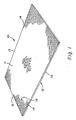
- a scored fiberboard 10 defines upper and lower major faces 11 and 12, respectively, and longitudinal edges 13. Intermittent incisions 14 in the face 11 lie along imaginary lines parallel to the longitudinal edges 13 and intermittent incisions 15 lie along imaginary lines perpendicular to those edges. Fibers in the surface region of the board are severed but are not removed from the board. The severed ends of the fibers are displaced initially by the thin blade of a cutting instrument but the consequent compression of the adjacent masses of fiber and binder is relieved somewhat as the blade is removed and as the severed ends of the fibers move back to substantially contiguous positions in response to that compression.
- a board having intermittent incisions in only one direction, i.e., along one or more lines parallel to or perpendicular to a longitudinal edge is useful when a design on the molded hardboard formed therefrom is to be unidirectional. Generally, however, it is preferred to make incisions along intersecting lines so that the board is adapted to improved moldability regardless of the orientation of the design on the die set.
- the intersecting sets of parallel lines defined by the incisions and the discontinuities therebetween are shown in FIG. 1 at right angles to one another but they may meet at acute angles.
- An advantage of the grid shown is the relative ease of designing and operating an apparatus for scoring a continuously moving board at right angles to the direction of movement as opposed to acute angles.
- the illustration in FIG. 1 of a grid of incisions on various portions of the face 11 is representative of a grid extending over the entire face of the board. It will also be understood that the face 12 may be incised in like manner.
- the discontinuities 16 or intervals of uncut surface between incisions along the imaginary lines have a maximum length of about 0.5 inch but they must be at least about 0.1 inch long. It is these intervals of uncut fibers that preserve the integrity of the face of the board during the molding operation. It has been found that when continuous parallel incisions are made in a dry, water-felted board, the severed fibers pulled apart during the molding operation, leaving gaps in the surface of the molded board which gave it an unsightly, unacceptable appearance.
- a fiberboard 20 is moved by a conveyor belt 21 into engagement with a rotating cylinder-like assembly 22 of toothed cutting disks 23 which are mounted co-axially in spaced-apart relation on a shaft 24 which is driven by a motor 25 in the direction indicated by an arrow A.
- the longitudinal incisions 14 are made as the deltoid teeth or blades 26 cut into the surface region of the face 11, as shown more clearly in FIG. 4.
- the incisions may be made by a razor blade, severance rather than separation of the fibers being a critical feature of this method, along with the intermittency of the incisions.
- the blades 26 are preferably wedge-shaped, having a thickness of as much as about 0.1 inch at their origin on the disk 23 and a razor-thin cutting edge.
- the transversely oriented incisions 15 are cut into the face 11 after the longitudinally oriented incisions 14 have been made.
- the board 20 is moved by the conveyor belt 21 onto a conveyor belt 27 which is activated when the leading edge of the board 20 has traversed the width of the belt 27 and bumped a trigger switch 28.
- the board 20 is then carried along a path at right angles to the belt 21 so that an assembly 22a of cutting disks may make the incisions 15.
- the fiberboard 10 is the product.
- a metal cylinder having multiple blades formed around its circumference by a machining operation.
- Such blades may be axially aligned for cutting the intermittent incisions 15 perpendicular to the longitudinal edges of the fiberboard or circumferentially aligned for cutting the intermittent incisions 14.
- the circumferentially aligned blades may have arcuate cutting edges instead of the saw tooth shape of the blades 26 but have divergent leading and trailing edges similar to those of the blades 26.
- the depth and spacing of the incisions 14 are shown in FIG. 5.
- the depth of the incisions in each face of the fiberboard may be from about 10% to about 30% or even up to about one-third of the thickness of the board.
- a 0.75 inch thick board may have incisions about 0.25 inch deep in the face which is to be pressed inwardly by the die having the negative of the desired profile. If the appearance of the obverse face of the molded hardboard is important, both faces will be incised to a depth appropriate to the contours and angles of the die set.
- the spacing between the parallel paths of the incisions 14 (and of the incisions 15) may be as large as about 0.5 inch but the fidelity of molding and the avoidance of stretch marks are better served by closer spacing, down to as little as about 0.1 inch or even less. It is preferred that a line of incisions in the board's face is generally oriented in the same direction as the margin of the design on a die and is located on the face so that there will be no more than about 0.25 inch between that line and the locus of contact points made by a die when the die set is closed upon the fiberboard.
- the surface of the scored fiberboard may be sprayed very lightly with water or an aqueous solution containing 20 wt.% urea and 10 wt.% of Glidden's Fibertight sealer, or equivalent materials, just prior to molding.
- the specific gravity of the molded hardboard is about 1.0-1.2 and the internal bond strength is 100-200 psi.
- Molded hardboards 60 and 70 of FIGS. 6 and 7, respectively, were made under substantially the same conditions from redwood fiberboards.
- a comparison of the hardboard 60 made according to the invention and the hardboard 70 made according to the prior art demonstrates the superiority of the product made from the incised fiberboard of this invention.
- Stretch marks 72 clearly visible in the board 70, are absent from the board 60. These stretch marks are visible as fuzzy lines even on a painted hardboard because of the uneven response to the paint.
Abstract
Description
- This invention relates to the molding of a composite board of cellulosic fibers between matched die sets to produce a high density, three dimensional board free of stretch marks and fractures. According to the invention, hardboard door facings may be molded with a high degree of fidelity to the contours and angles of the die set bearing the pattern of the desired profile.
- The fibers of a rigid fiberboard, made of the consolidation of a water-felted mat under heat and pressure, are bound together primarily by hydrogen bonding and mechanical interlocking but also by the lignin native to the fibers. Such a fiberboard is difficult to consolidate into thin, non-planar panels without causing stretch marks and even fractures in deeply molded regions or regions adjacent thereto. In a molding press, the tension and compression forces pull and push the fibers in a rigid fiberboard apart, sometimes to the breaking point. This is a particularly significant problem with fiberboards having little or no resinous binders which would flow in response to said forces to take the place of the relatively inelastic fibers which cannot flow around the contours and angles of the die set.
- The fibers of a dry felted wood fiber mat, on the other hand, are loosely bound together by a synthetic thermosetting resin and can flow along with the resin during hot pressure molding.
- C. C. Heritage teaches a method for improving the surfaces and strengthening contoured parts of a molded hardboard panel in Canadian Patent No. 572,073. Either dry- or water-felted wood fibers may be consolidated and molded to produce contoured hardboard, according to Heritage, by covering felted mats with an overlay of a thermoplastic or thermosetting resin in the form of a film, an impregnated fabric, or a coating.
- According to the teachings of Nishibori in U.S. Patent No. 4,610,900, there is a problem when a synthetic resin is mixed with a cellulosic aggregate prior to molding. The aggregate, such as pulverized wood chips, is added to the resin to prevent the residual internal stress in the molded product which leads to warping and twisting thereof. Large amounts of the cellulosic aggregate, however, hamper the flowability of the resin and produce internal stresses in the resin product to be molded. Nishibori solves the problem by: first, heating and cooling the resin product; second, removing a skin layer of resin from the surface of the product by sanding or sandblasting; and third, cutting grooves out of the resulting exposed surface. This last operation suffers from the disadvantages of loss of the material removed to make the grooves and the expense of waste collection and removal.
- It is an object of the invention to overcome one or more of the problems described above.
- The invention provides a simple, non-destructive, and relatively inexpensive method of improving the moldability of consolidated fiberboards, especially water-felted wood fiberboards.
- The invention also provides a rigid board of consolidated fibers which may be molded under pressure to a three dimensional board with high fidelity to the contour and angles of the mold.
- The invention further provides an improved method of producing deeply molded hardboard from consolidated, water-felted wood fiberboards whereby the molded hardboard is free from stretch marks and tears or fractures.
- According to the invention, one or more of the foregoing objectives is accomplished by providing a board of consolidated fibers having at least one face comprising a plurality of discontinuous incisions in the surface region thereof. Preferably, the board of consolidated fibers is molded into a non-planar board, and preferably at least some of the fibers are severed with the ends of the severed fibers being substantially contiguous.
- The invention also comprehends a method of molding a non-planar board, and an apparatus for cutting discontinuous incisions into the face of a board.
- Further objects and advantages of the invention will be apparent to those skilled in the art from a review of the following detailed description, taken in conjunction with the drawings and the appended claims.
- For a fuller understanding of this invention, reference should be made to the drawings, in which:
- FIG. 1 is a perspective view of a fiberboard having discontinuous incisions therein in accordance with the invention.
- FIG. 2 is a partially cut away perspective view of a fiberboard having discontinuous incisions being made into its upper surface parallel to its longitudinal edges as it moves under an assembly of co-axially mounted, toothed cutting disks.
- FIG. 3 is a top plan view of the apparatus of FIG. 2 in association with a similar apparatus set at right angles thereto.
- FIG. 4 is a side view of the fiberboard and apparatus of FIG. 2.
- FIG. 5 is an enlarged cross section of a board of this invention showing cuts in its surface region.
- FIG. 6 is a photograph of a deeply molded hardboard made from the incides fiberboard of this invention.
- FIG. 7 is a photograph of a deeply molded hardboard made from a fiberboard of the prior art having no incisions.
- According to the invention, a plurality of discontinuous incisions are made into the surface region of a major face of a fiberboard to sever fibers in the surface region without removing the fibers or other material therefrom, followed by molding the fiberboard. For the purposes of this invention, the surface region of a major face of the fiberboard extends inwardly for about one-third of the board's thickness. The discontinuous incisions define a line and may be made with a razor blade or similarly sharp cutting instrument having a thin blade, but it is preferred to use a cutting disk having circumferentially spaced notches in the blade.
- The fiberboard may be a dry, consolidated mass of cellulosic fibers such as paper pulp, wood fibers, or other lignocellulosic fibers. Its density is typically in the range of about 10 to about 28 lbs. per cubic foot, preferably up to about 22 lbs. per cubic foot. The invention is particularly advantageous in the molding of fiberboards made from long fibers such as redwood fibers. Although one important objective of the invention is to improve the moldability of wet-felted rigid fiberboards having no added binder, the invention is operative with fiberboards containing conventional binders such as resins, starch, tung oil and the like.
- In FIG. 1, a scored
fiberboard 10 defines upper and lowermajor faces 11 and 12, respectively, andlongitudinal edges 13.Intermittent incisions 14 in the face 11 lie along imaginary lines parallel to thelongitudinal edges 13 andintermittent incisions 15 lie along imaginary lines perpendicular to those edges. Fibers in the surface region of the board are severed but are not removed from the board. The severed ends of the fibers are displaced initially by the thin blade of a cutting instrument but the consequent compression of the adjacent masses of fiber and binder is relieved somewhat as the blade is removed and as the severed ends of the fibers move back to substantially contiguous positions in response to that compression. - A board having intermittent incisions in only one direction, i.e., along one or more lines parallel to or perpendicular to a longitudinal edge is useful when a design on the molded hardboard formed therefrom is to be unidirectional. Generally, however, it is preferred to make incisions along intersecting lines so that the board is adapted to improved moldability regardless of the orientation of the design on the die set. The intersecting sets of parallel lines defined by the incisions and the discontinuities therebetween are shown in FIG. 1 at right angles to one another but they may meet at acute angles. An advantage of the grid shown is the relative ease of designing and operating an apparatus for scoring a continuously moving board at right angles to the direction of movement as opposed to acute angles. The illustration in FIG. 1 of a grid of incisions on various portions of the face 11 is representative of a grid extending over the entire face of the board. It will also be understood that the
face 12 may be incised in like manner. - The
discontinuities 16 or intervals of uncut surface between incisions along the imaginary lines have a maximum length of about 0.5 inch but they must be at least about 0.1 inch long. It is these intervals of uncut fibers that preserve the integrity of the face of the board during the molding operation. It has been found that when continuous parallel incisions are made in a dry, water-felted board, the severed fibers pulled apart during the molding operation, leaving gaps in the surface of the molded board which gave it an unsightly, unacceptable appearance. - In FIG. 2, a
fiberboard 20 is moved by aconveyor belt 21 into engagement with a rotating cylinder-like assembly 22 oftoothed cutting disks 23 which are mounted co-axially in spaced-apart relation on ashaft 24 which is driven by amotor 25 in the direction indicated by an arrow A. Thelongitudinal incisions 14 are made as the deltoid teeth orblades 26 cut into the surface region of the face 11, as shown more clearly in FIG. 4. - As mentioned above, the incisions may be made by a razor blade, severance rather than separation of the fibers being a critical feature of this method, along with the intermittency of the incisions. Because of the limitations of strength of extremely thin blades, however, the
blades 26 are preferably wedge-shaped, having a thickness of as much as about 0.1 inch at their origin on thedisk 23 and a razor-thin cutting edge. - In FIG. 3, the transversely
oriented incisions 15 are cut into the face 11 after the longitudinallyoriented incisions 14 have been made. Theboard 20 is moved by theconveyor belt 21 onto aconveyor belt 27 which is activated when the leading edge of theboard 20 has traversed the width of thebelt 27 and bumped atrigger switch 28. Theboard 20 is then carried along a path at right angles to thebelt 21 so that anassembly 22a of cutting disks may make theincisions 15. Thefiberboard 10 is the product. - Several alternatives to an assembly of cutting disks are contemplated for use as the cutting apparatus of this invention, among which is a metal cylinder having multiple blades formed around its circumference by a machining operation. Such blades may be axially aligned for cutting the
intermittent incisions 15 perpendicular to the longitudinal edges of the fiberboard or circumferentially aligned for cutting theintermittent incisions 14. The circumferentially aligned blades may have arcuate cutting edges instead of the saw tooth shape of theblades 26 but have divergent leading and trailing edges similar to those of theblades 26. - The depth and spacing of the
incisions 14 are shown in FIG. 5. The depth of the incisions in each face of the fiberboard may be from about 10% to about 30% or even up to about one-third of the thickness of the board. For example, a 0.75 inch thick board may have incisions about 0.25 inch deep in the face which is to be pressed inwardly by the die having the negative of the desired profile. If the appearance of the obverse face of the molded hardboard is important, both faces will be incised to a depth appropriate to the contours and angles of the die set. The spacing between the parallel paths of the incisions 14 (and of the incisions 15) may be as large as about 0.5 inch but the fidelity of molding and the avoidance of stretch marks are better served by closer spacing, down to as little as about 0.1 inch or even less. It is preferred that a line of incisions in the board's face is generally oriented in the same direction as the margin of the design on a die and is located on the face so that there will be no more than about 0.25 inch between that line and the locus of contact points made by a die when the die set is closed upon the fiberboard. - Conventional conditions of temperature and pressure may be used for the deep molding of the scored fiberboard between matched die sets. A breathe press cycle is preferred over constant pressure. The surface of the scored fiberboard may be sprayed very lightly with water or an aqueous solution containing 20 wt.% urea and 10 wt.% of Glidden's Fibertight sealer, or equivalent materials, just prior to molding. The specific gravity of the molded hardboard is about 1.0-1.2 and the internal bond strength is 100-200 psi.
- Molded hardboards 60 and 70 of FIGS. 6 and 7, respectively, were made under substantially the same conditions from redwood fiberboards.
- A comparison of the
hardboard 60 made according to the invention and thehardboard 70 made according to the prior art demonstrates the superiority of the product made from the incised fiberboard of this invention. Stretch marks 72, clearly visible in theboard 70, are absent from theboard 60. These stretch marks are visible as fuzzy lines even on a painted hardboard because of the uneven response to the paint. - It will be appreciated that the invention may be practiced in various ways within the spirit and scope of the following claims.
Claims (17)
providing a dry board of consolidated fibers;
making a plurality of discontinuous incisions in a surface region of at least one face of said dry board; and
compressing said dry board with a die set bearing a pattern of a desired profile.
said dry board is provided by water-felting and consolidating fibers to make a fiberboard and drying the fiberboard; and
said dry board is compressed with a heated die set bearing a pattern of the desired profile.
means for transporting said board linearly;
a cyclindrical cutter mounted above said transporting means, said cutter having multiple of blades arrayed around the circumference of said cutter, said blades each comprising a first cutting edge extending below the plane of said board face, and second and third cutting edges diverging from said first cutting edge toward adjacent blades; and
means for rotating said cutter in cutting engagement with said board face.
Applications Claiming Priority (2)
| Application Number | Priority Date | Filing Date | Title |
|---|---|---|---|
| US22919788A | 1988-08-05 | 1988-08-05 | |
| US229197 | 1988-08-05 |
Publications (3)
| Publication Number | Publication Date |
|---|---|
| EP0353564A2 true EP0353564A2 (en) | 1990-02-07 |
| EP0353564A3 EP0353564A3 (en) | 1992-01-02 |
| EP0353564B1 EP0353564B1 (en) | 1995-08-23 |
Family
ID=22860198
Family Applications (1)
| Application Number | Title | Priority Date | Filing Date |
|---|---|---|---|
| EP89113434A Expired - Lifetime EP0353564B1 (en) | 1988-08-05 | 1989-07-21 | Scored fiberboard having improved moldability |
Country Status (13)
| Country | Link |
|---|---|
| EP (1) | EP0353564B1 (en) |
| JP (1) | JPH0829531B2 (en) |
| KR (1) | KR0152520B1 (en) |
| AU (1) | AU621392B2 (en) |
| BR (1) | BR8903934A (en) |
| CA (1) | CA1331683C (en) |
| DE (1) | DE68923923T2 (en) |
| ES (1) | ES2075015T3 (en) |
| FI (1) | FI92424C (en) |
| MX (1) | MX171818B (en) |
| NO (1) | NO305231B1 (en) |
| NZ (2) | NZ230209A (en) |
| ZA (1) | ZA895192B (en) |
Cited By (2)
| Publication number | Priority date | Publication date | Assignee | Title |
|---|---|---|---|---|
| FR2700566A1 (en) * | 1993-01-21 | 1994-07-22 | Lee Eun Hwan | Building plate |
| GB2436084A (en) * | 2006-03-17 | 2007-09-19 | Kevin Tomes | Folding and joining composite boards |
Families Citing this family (8)
| Publication number | Priority date | Publication date | Assignee | Title |
|---|---|---|---|---|
| MXPA03009030A (en) | 2001-04-03 | 2004-02-12 | James Hardie Res Pty Ltd | Reinforced fiber cement article, methods of making and installing. |
| KR20030005881A (en) * | 2001-07-10 | 2003-01-23 | 김월임 | A cleanser using sericite powder and the method of cleaning |
| US8281535B2 (en) | 2002-07-16 | 2012-10-09 | James Hardie Technology Limited | Packaging prefinished fiber cement articles |
| AR040590A1 (en) | 2002-07-16 | 2005-04-13 | James Hardie Res Pty Ltd | PROTECTED PRE-FABRICED FIBER CEMENT PRODUCTS |
| MXPA05003691A (en) | 2002-10-07 | 2005-11-17 | James Hardie Int Finance Bv | Durable medium-density fibre cement composite. |
| US7998571B2 (en) | 2004-07-09 | 2011-08-16 | James Hardie Technology Limited | Composite cement article incorporating a powder coating and methods of making same |
| KR100781932B1 (en) * | 2005-11-28 | 2007-12-04 | 주식회사 엘지화학 | In-line Process for Preparing Wood Plastic Composite Panel with the Appearance and Texture Similar to Natural Lumbers and Apparatus therefore |
| NZ571874A (en) | 2006-04-12 | 2010-11-26 | Hardie James Technology Ltd | A surface sealed reinforced building element |
Citations (5)
| Publication number | Priority date | Publication date | Assignee | Title |
|---|---|---|---|---|
| US2800423A (en) * | 1954-10-18 | 1957-07-23 | Swart Dev Company De | Molded article of stretchable glass cloth |
| FR1384835A (en) * | 1963-11-29 | 1965-01-08 | Tissage Des Avenieres | Glass fabric for three-dimensional reinforcement of a laminate and method of obtaining this fabric |
| GB1510412A (en) * | 1976-03-12 | 1978-05-10 | Dresser Corp | Method of forming a curved flexible substantially self-supporting sheet like structure |
| JPS60224530A (en) * | 1984-04-23 | 1985-11-08 | Mazda Motor Corp | Composite resin sheet containing reinforcing fiber |
| EP0248248B1 (en) * | 1986-05-23 | 1991-08-07 | International Business Machines Corporation | Method for making a substantially planar construction of resin impregnated fabric |
Family Cites Families (5)
| Publication number | Priority date | Publication date | Assignee | Title |
|---|---|---|---|---|
| US3314339A (en) * | 1964-05-04 | 1967-04-18 | Inland Container Corp | Scoring device |
| US3731600A (en) * | 1971-03-16 | 1973-05-08 | Ex Cell O Corp | Resilient female scoring |
| US3983827A (en) * | 1975-12-05 | 1976-10-05 | Peerless Machine & Tool Corporation | Tab scoring for containers and lids |
| JPS5539460A (en) * | 1978-09-14 | 1980-03-19 | Matsushita Electric Ind Co Ltd | Headphone |
| JPS563174A (en) * | 1979-06-25 | 1981-01-13 | Okamoto Seikou Kk | Water grinding process and device therefor |
-
1989
- 1989-07-07 ZA ZA895192A patent/ZA895192B/en unknown
- 1989-07-21 EP EP89113434A patent/EP0353564B1/en not_active Expired - Lifetime
- 1989-07-21 DE DE68923923T patent/DE68923923T2/en not_active Expired - Fee Related
- 1989-07-21 ES ES89113434T patent/ES2075015T3/en not_active Expired - Lifetime
- 1989-07-25 JP JP1190715A patent/JPH0829531B2/en not_active Expired - Lifetime
- 1989-07-25 CA CA000606593A patent/CA1331683C/en not_active Expired - Fee Related
- 1989-08-02 AU AU39225/89A patent/AU621392B2/en not_active Ceased
- 1989-08-03 NO NO893144A patent/NO305231B1/en unknown
- 1989-08-04 NZ NZ230209A patent/NZ230209A/en unknown
- 1989-08-04 MX MX017083A patent/MX171818B/en unknown
- 1989-08-04 FI FI893706A patent/FI92424C/en not_active IP Right Cessation
- 1989-08-04 BR BR898903934A patent/BR8903934A/en not_active IP Right Cessation
- 1989-08-04 NZ NZ247463A patent/NZ247463A/en unknown
- 1989-08-04 KR KR1019890011231A patent/KR0152520B1/en not_active IP Right Cessation
Patent Citations (5)
| Publication number | Priority date | Publication date | Assignee | Title |
|---|---|---|---|---|
| US2800423A (en) * | 1954-10-18 | 1957-07-23 | Swart Dev Company De | Molded article of stretchable glass cloth |
| FR1384835A (en) * | 1963-11-29 | 1965-01-08 | Tissage Des Avenieres | Glass fabric for three-dimensional reinforcement of a laminate and method of obtaining this fabric |
| GB1510412A (en) * | 1976-03-12 | 1978-05-10 | Dresser Corp | Method of forming a curved flexible substantially self-supporting sheet like structure |
| JPS60224530A (en) * | 1984-04-23 | 1985-11-08 | Mazda Motor Corp | Composite resin sheet containing reinforcing fiber |
| EP0248248B1 (en) * | 1986-05-23 | 1991-08-07 | International Business Machines Corporation | Method for making a substantially planar construction of resin impregnated fabric |
Non-Patent Citations (1)
| Title |
|---|
| PATENT ABSTRACTS OF JAPAN, vol. 10, no. 83 (M-466)[2140], 2nd April 1986; & JP-A-60 224 530 (MAZDA K.K.) 08-11-1985 * |
Cited By (2)
| Publication number | Priority date | Publication date | Assignee | Title |
|---|---|---|---|---|
| FR2700566A1 (en) * | 1993-01-21 | 1994-07-22 | Lee Eun Hwan | Building plate |
| GB2436084A (en) * | 2006-03-17 | 2007-09-19 | Kevin Tomes | Folding and joining composite boards |
Also Published As
| Publication number | Publication date |
|---|---|
| EP0353564B1 (en) | 1995-08-23 |
| JPH0260711A (en) | 1990-03-01 |
| BR8903934A (en) | 1990-03-20 |
| ES2075015T3 (en) | 1995-10-01 |
| KR0152520B1 (en) | 1998-10-01 |
| DE68923923D1 (en) | 1995-09-28 |
| AU621392B2 (en) | 1992-03-12 |
| DE68923923T2 (en) | 1996-01-04 |
| NZ230209A (en) | 1993-12-23 |
| KR900002937A (en) | 1990-03-23 |
| FI92424B (en) | 1994-07-29 |
| FI893706A0 (en) | 1989-08-04 |
| FI92424C (en) | 1994-11-10 |
| NO305231B1 (en) | 1999-04-26 |
| MX171818B (en) | 1993-11-17 |
| ZA895192B (en) | 1990-04-25 |
| NO893144L (en) | 1990-02-06 |
| FI893706A (en) | 1990-02-06 |
| JPH0829531B2 (en) | 1996-03-27 |
| NO893144D0 (en) | 1989-08-03 |
| AU3922589A (en) | 1990-02-08 |
| CA1331683C (en) | 1994-08-30 |
| EP0353564A3 (en) | 1992-01-02 |
| NZ247463A (en) | 1993-12-23 |
Similar Documents
| Publication | Publication Date | Title |
|---|---|---|
| US5489460A (en) | Molded non-planar board and method and apparatus for making same | |
| US3868300A (en) | Method of making a composite panel laminate having deep indentations | |
| US4751131A (en) | Waferboard lumber | |
| US2773789A (en) | Crosscut fiber and method for its preparation | |
| EP0353564B1 (en) | Scored fiberboard having improved moldability | |
| US3661491A (en) | Means for producing fibrous products having integral tongue and groove edges | |
| US7096916B2 (en) | Method of manufacturing consolidated cellulosic panels with contoured surfaces and variable basis weight | |
| US2776686A (en) | Crosscut fiber and method for its preparation | |
| US3549738A (en) | Method for producing fibrous products having integral tongue and groove edges | |
| US2786005A (en) | Crosscut woody wafers and structures embodying same | |
| US6895723B2 (en) | Compressed wood waste structural I-beam | |
| US7004215B2 (en) | Compressed wood waste structural beams | |
| CA1281528C (en) | Waferboard lumber | |
| DE4201201C2 (en) | Flat or curved semi-finished or finished product made of wood-based materials for use in furniture or interior design, in packaging material production, in wood products production or in building construction with a wall thickness between 2 mm and 1000 mm and process for its production | |
| USRE34283E (en) | Waferboard lumber | |
| CA1289442C (en) | Process for the production of a veneer workpiece with cutout, as well aspressure punching tool for performing the same | |
| US2776687A (en) | Crosscut fiber and method for its preparation | |
| US2776688A (en) | Crosscut fiber and method for its preparation | |
| US4828642A (en) | Process for the manufacture of parquet flooring blocks | |
| US3835902A (en) | Method of composing wide continuous bands of veneer | |
| CN2241620Y (en) | Partial edge-covering hard shell for hot-pressed formed board | |
| US20010035071A1 (en) | Dieboard and method of construction | |
| DE20022894U1 (en) | Punching tool for producing openings in workpieces made of thermoplastic material | |
| JPH0729274B2 (en) | A blade that cuts a sheet to form a serrated edge |
Legal Events
| Date | Code | Title | Description |
|---|---|---|---|
| PUAI | Public reference made under article 153(3) epc to a published international application that has entered the european phase |
Free format text: ORIGINAL CODE: 0009012 |
|
| AK | Designated contracting states |
Kind code of ref document: A2 Designated state(s): DE ES FR GB SE |
|
| 17P | Request for examination filed |
Effective date: 19901228 |
|
| PUAL | Search report despatched |
Free format text: ORIGINAL CODE: 0009013 |
|
| AK | Designated contracting states |
Kind code of ref document: A3 Designated state(s): DE ES FR GB SE |
|
| 17Q | First examination report despatched |
Effective date: 19930628 |
|
| GRAA | (expected) grant |
Free format text: ORIGINAL CODE: 0009210 |
|
| AK | Designated contracting states |
Kind code of ref document: B1 Designated state(s): DE ES FR GB SE |
|
| ET | Fr: translation filed | ||
| REF | Corresponds to: |
Ref document number: 68923923 Country of ref document: DE Date of ref document: 19950928 |
|
| REG | Reference to a national code |
Ref country code: ES Ref legal event code: FG2A Ref document number: 2075015 Country of ref document: ES Kind code of ref document: T3 |
|
| PLBE | No opposition filed within time limit |
Free format text: ORIGINAL CODE: 0009261 |
|
| STAA | Information on the status of an ep patent application or granted ep patent |
Free format text: STATUS: NO OPPOSITION FILED WITHIN TIME LIMIT |
|
| 26N | No opposition filed | ||
| REG | Reference to a national code |
Ref country code: GB Ref legal event code: IF02 |
|
| PGFP | Annual fee paid to national office [announced via postgrant information from national office to epo] |
Ref country code: FR Payment date: 20020702 Year of fee payment: 14 |
|
| PGFP | Annual fee paid to national office [announced via postgrant information from national office to epo] |
Ref country code: GB Payment date: 20020717 Year of fee payment: 14 |
|
| PGFP | Annual fee paid to national office [announced via postgrant information from national office to epo] |
Ref country code: ES Payment date: 20020807 Year of fee payment: 14 |
|
| PG25 | Lapsed in a contracting state [announced via postgrant information from national office to epo] |
Ref country code: GB Free format text: LAPSE BECAUSE OF NON-PAYMENT OF DUE FEES Effective date: 20030721 |
|
| PG25 | Lapsed in a contracting state [announced via postgrant information from national office to epo] |
Ref country code: ES Free format text: LAPSE BECAUSE OF NON-PAYMENT OF DUE FEES Effective date: 20030722 |
|
| GBPC | Gb: european patent ceased through non-payment of renewal fee |
Effective date: 20030721 |
|
| PG25 | Lapsed in a contracting state [announced via postgrant information from national office to epo] |
Ref country code: FR Free format text: LAPSE BECAUSE OF NON-PAYMENT OF DUE FEES Effective date: 20040331 |
|
| REG | Reference to a national code |
Ref country code: FR Ref legal event code: ST |
|
| PGFP | Annual fee paid to national office [announced via postgrant information from national office to epo] |
Ref country code: SE Payment date: 20040721 Year of fee payment: 16 |
|
| PGFP | Annual fee paid to national office [announced via postgrant information from national office to epo] |
Ref country code: DE Payment date: 20040831 Year of fee payment: 16 |
|
| REG | Reference to a national code |
Ref country code: ES Ref legal event code: FD2A Effective date: 20030722 |
|
| PG25 | Lapsed in a contracting state [announced via postgrant information from national office to epo] |
Ref country code: SE Free format text: LAPSE BECAUSE OF NON-PAYMENT OF DUE FEES Effective date: 20050722 |
|
| PG25 | Lapsed in a contracting state [announced via postgrant information from national office to epo] |
Ref country code: DE Free format text: LAPSE BECAUSE OF NON-PAYMENT OF DUE FEES Effective date: 20060201 |
|
| EUG | Se: european patent has lapsed |