EP0353556B1 - Device for storing elongate articles - Google Patents
Device for storing elongate articles Download PDFInfo
- Publication number
- EP0353556B1 EP0353556B1 EP89113415A EP89113415A EP0353556B1 EP 0353556 B1 EP0353556 B1 EP 0353556B1 EP 89113415 A EP89113415 A EP 89113415A EP 89113415 A EP89113415 A EP 89113415A EP 0353556 B1 EP0353556 B1 EP 0353556B1
- Authority
- EP
- European Patent Office
- Prior art keywords
- container
- transverse rollers
- chain
- drive
- rollers
- Prior art date
- Legal status (The legal status is an assumption and is not a legal conclusion. Google has not performed a legal analysis and makes no representation as to the accuracy of the status listed.)
- Expired - Lifetime
Links
Images


Classifications
-
- B—PERFORMING OPERATIONS; TRANSPORTING
- B65—CONVEYING; PACKING; STORING; HANDLING THIN OR FILAMENTARY MATERIAL
- B65G—TRANSPORT OR STORAGE DEVICES, e.g. CONVEYORS FOR LOADING OR TIPPING, SHOP CONVEYOR SYSTEMS OR PNEUMATIC TUBE CONVEYORS
- B65G1/00—Storing articles, individually or in orderly arrangement, in warehouses or magazines
- B65G1/02—Storage devices
- B65G1/04—Storage devices mechanical
- B65G1/0407—Storage devices mechanical using stacker cranes
- B65G1/0414—Storage devices mechanical using stacker cranes provided with satellite cars adapted to travel in storage racks
-
- B—PERFORMING OPERATIONS; TRANSPORTING
- B65—CONVEYING; PACKING; STORING; HANDLING THIN OR FILAMENTARY MATERIAL
- B65G—TRANSPORT OR STORAGE DEVICES, e.g. CONVEYORS FOR LOADING OR TIPPING, SHOP CONVEYOR SYSTEMS OR PNEUMATIC TUBE CONVEYORS
- B65G1/00—Storing articles, individually or in orderly arrangement, in warehouses or magazines
- B65G1/02—Storage devices
- B65G1/04—Storage devices mechanical
- B65G1/0442—Storage devices mechanical for elongated articles
Definitions
- the invention relates to a device for storing long goods, for example pipes, rods or the like, on a shelf which comprises a plurality of receiving spaces for long goods, with a mobile receiving carriage which can be moved from the front side into the receiving spaces of the shelf by means of a drive device is.
- the rack arrangement has receiving compartments with associated, displaceable receiving carriages and a separate loading and unloading carriage. This can be moved on the opening side of the storage compartments transversely to these and has a height-adjustable platform which can be aligned with the individual storage compartments for the purpose of taking over the storage trolley.
- the loading and unloading trolley runs on tracks or in a recessed track by means of rollers and is thus bound to the track or lane.
- the known design is also structurally extremely complex and unsuitable to transport long goods, such as pipes, rods or the like, without using lanes or rails.
- Another known device (DE-A-2 243 107) relates to a pallet truck for loading a high-bay warehouse with a shelf operating device and a lifting platform that can be moved in front of the high-bay warehouse.
- the pallet truck can be moved in rails that are installed both in the lifting platform and in individual shelf compartments, and has caterpillar tracks on the side to make it easier to move between these rails even when the rails are inexactly aligned on the high rack and in the lifting platform, even when doing so larger distances must be bridged between the rails.
- the invention has for its object to provide a device with the features of the generic term so that rails are no longer required to retract the receiving goods receiving the long goods and thus an individual constructive adjustment of the receiving carriage and the shelf is no longer necessary, so that the shelves easier, lighter in weight and thus cheaper to manufacture.
- the receiving carriage is designed as a trough-like, open-sided container, which is equipped for the transport of the long goods with caterpillars, which are deflected via end sprockets, this can be used in all conventional shelves, without special rails adapted to the track width of the container have to be. Accordingly, the arrangement of special L- and U-shaped profiled guide rails on the shelves not necessary anymore; the trough-shaped, caterpillar-equipped receiving trolley can thus also be inserted into existing shelves, which are only formed by vertical stands and horizontal crossbars connecting and stiffening them, provided that the width of the individual storage spaces on top of and next to each other is sufficiently large.
- a further advantage lies in the fact that several trough-like containers provided with caterpillar tracks can be inserted next to one another into correspondingly wide receiving spaces due to the design according to the invention. Furthermore, since a drive device for the mobile container is arranged on the container itself and the long goods are supported on transverse rollers in the container, easy loading and unloading as well as simple, effortless transport of the long goods is ensured even with long goods weighing tons.
- the lower section thereof is designed as a guide profile open at the bottom, which guides the caterpillar chain and from which the caterpillar chain protrudes with its running surface.
- This arrangement not only contributes to the increased stability and torsional rigidity of the trough-shaped container, but also serves for the exact guidance of the caterpillar chain and thus for the targeted positioning of the container in the receiving spaces.
- the drive device can be equipped with means which ensure a synchronous drive of both caterpillar tracks.
- Different versions of this are possible; one may consist in that a motor equipped with two shaft ends acts on the chain wheels or that a drive motor equipped with a drive shaft acts equally on both caterpillar tracks via a connecting shaft. If a low speed drive motor is used to move the container at a reasonable speed, a reduction gear and the motor can be directly coupled to the sprockets.
- An embodiment variant of the drive device also consists in that a drive motor acts on the running surfaces of the crawler belt with the interposition of friction wheels.
- the picking process is ended by the long goods being deposited on the cross members in the intended receiving space.
- the removal of the long goods from the container and deposits on the cross members can be done, for example, by the fact that a slide is provided which has the inner cross-sectional shape of the container and is movable relative to the container, so that when the container is extended from a receiving space, the long goods are opened the cross rollers are rolled out of the container.
- the number of cross rollers must be measured. It has been found that in the case of the commercial dimensions of long goods, which are approximately 6 m to 7 m, at least five transverse rollers, but preferably seven transverse rollers, are to be provided. These transverse rollers should have the same diameter and be arranged at approximately the same intervals over the length of the container. To discharge the long goods, it is particularly expedient that at least a part of the total number of transverse rollers can be driven, so that the long goods are moved out of the container by the rotational movement of the rollers. In this regard, it is particularly advantageous that the transverse rollers are provided with a chain or drive wheel, over which a conveyor chain or a drive belt is stretched.
- the caterpillar tracks, the conveyor chain and / or the drive belt are provided with tensioning means, which are preferably designed as tensioning rollers.
- a cover attached to one of the side wall parts which covers the drive means of the transverse rollers. It is particularly expedient for the cover to run at a short distance above the transverse rollers and to have downwardly projecting sections in the region between the transverse rollers. In this way it is ensured that the loading of the container with long goods is possible without special precautionary measures and the drive means for the transverse rollers are protected from any damage with certainty.
- a particularly preferred embodiment of the drive of the transverse rollers consists in that the conveyor chain is tensioned via a drive sprocket which is mounted on a shaft together with one of the sprockets of the caterpillar tracks, but can be driven independently of this.
- This independent driving is important because the transverse rollers of the transport of the long goods are fixed up to the receiving space and can only be driven in the receiving space provided for storing the long goods.
- the drive sprocket can be connected to the sprocket of the caterpillar chain if necessary via a clutch. This can suitably be a claw coupling or a similar type of coupling in which the coupling parts are in positive engagement.
- a particularly suitable embodiment of the invention is given when the direction of rotation of the transverse rollers is opposite is the direction of movement of the container, the speed on the lateral surface of the transverse rollers being equal to the speed of the container.
- the speed on the lateral surface of the transverse rollers being equal to the speed of the container.
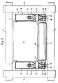
- Fig. 1 shows the schematic structure of a long goods store, of which two rows of shelves 1a and 1b are shown with an aisle 2 located between them.
- a lifting platform 3 can be moved horizontally and vertically between the rows of shelves 1a and 1b.
- the lifting platform 3 is used for conveying the height of a trough-shaped container 4 to the individual receiving spaces 5, one above the other and in the horizontal direction, which are formed by vertical stands 6 and horizontal cross bars 7.
- the receiving spaces 5 are used to store the different types of long goods 8, such as rods, pipes or the like.
- Lowerable slides 9 are arranged on the lifting device 3, the function of which will be explained in more detail later in FIG. 2.
- the container 4 is equipped with caterpillar tracks, by means of which the container 4 can be moved in and out in the direction of arrow F into the receiving spaces 5.
- the structure of the device is described in more detail with reference to the other figures.
- Fig. 2 shows a section through a container 4 for receiving long goods
- the trough shape of the container 4 is formed by the side wall parts 10 and the transverse rollers 11 arranged between them. Since the transverse rollers 11 rotatably mounted on the wall parts 10 could not produce the required rigidity of the trough-shaped container 4, the side wall parts 10 are - as shown in FIG. 3 - joined together to form a rigid frame via welded-on cross members 12. However, since the upper surface lines 11a of the transverse rollers 11 lie higher than the upper edges 12a of the transverse beams 12 (see FIG. 3), the transverse rollers 11 form a support and thus the bottom of the container 4 on which the (not shown in FIG. 2) ) Long goods lies.
- the container 4 drawn in cross section is shown in Fig. 2 so that it is located in a receiving space 5 of the shelf between the stand 6 and 7 cross members.
- a slide 9 is also shown in the lowered position, by means of which the long goods are held in their position when the container 4 is extended from the receiving space 5 and are thus slid out of the container 4 on the rollers 11.
- the lower part of the sprocket 13 protruding a corresponding opening 15 in the lower portion of the wall part 10 in a guide profile 16 connected to this lower wall part.
- An endless caterpillar track 17 is stretched over the chain wheels 13, the chains being guided exactly in the guide profiles 16.
- the lower links of the caterpillar track 17 protrude from the guide profiles 16 on the underside and thus form the running surface 18 of the caterpillar tracks 17. It goes without saying that the guide profiles 16 have the openings 15 only in the area of the sprockets 13, but for the rest the side wall parts are closed, as can be seen from FIGS. 2 and 3.
- the container 4 which contains the long goods 8 and which is located on the lifting platform 3, is brought into a position in which the container is positioned in an exactly aligned manner in front of an empty receiving space 5.
- the container 4 the caterpillar tracks of which can be driven by a drive device, is completely moved into the receiving space 5, as a result of which the long goods to be picked are also completely located within the receiving space 5.
- Fig. 4b The slider 9 arranged on the lifting platform 3 is then lowered, so that an end face of the container 4 closes while maintaining a small distance from the transverse rollers 11 and lateral wall parts 10.
- FIG. 2 With regard to the position that the slide 9 assumes, reference is made to the illustration in FIG. 2.
- the container 4 is moved out of the receiving space back onto the lifting platform 3, as shown in FIG. 4c. Since the lowered slider 9 holds the long goods 8 in place, the long goods roll off Cross rollers 11 down and lies on the cross bars 7 of the shelf row 1a. The empty container 4 is then available for further filling with long goods and for the next picking process.
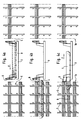
- FIG. 5 again shows a section through a container 4, which is located in a receiving space 5, the section being made through the axes of the chain wheels. Since this is a representation which essentially corresponds to that in FIG. 2, the reference numerals of FIG. 2 are used for the same parts.
- FIG. 5 shows the long goods 8 lying on the transverse rollers 11 in the form of round bars.
- the alternative embodiment of FIG. 5 differs from that in FIG. 2 in that the transverse rollers 11 are provided with a drive device by means of which the rollers 11 can be set in rotation and thus deposit the long goods.
- the sprocket 13 shown on the left in FIG. 5 is fastened to an elongated shaft 19 which projects into the interior of the container 4.
- a drive sprocket 20 On a section of this extended shaft 19 there is a drive sprocket 20, which is freely supported on the shaft 19.
- a conveyor chain 21 is tensioned over the drive sprocket 20 and is used to drive the transverse rollers 11 as required.
- a coupling part 23 On a pin 22 of the shaft 19, a coupling part 23 is fastened in a rotationally fixed but axially displaceable manner, which can be brought into engagement in the manner of a claw coupling with coupling bolts 24 projecting from the drive sprocket 20 in the axial direction.
- Fig. 5 the upper half of the coupling part 23 is shown in the uncoupled position and the lower half 23 'of the coupling part in the coupled state.
- This drive mechanism for the transverse rollers 11 is covered by a sheet metal hood 25 screwed onto the side wall part 10. This sheet metal hood 25 serves on the one hand as accident prevention protection and on the other hand to protect the drive means from being damaged by the long goods 8.
- Fig. 6 shows a section through a device according to FIG. 5, but in a different plane, and more in the middle of the container 4. From this illustration it can be seen that the caterpillar tracks 17 both with respect to the upper horizontal movement - ie their upper run - As well as the lower horizontal movement - so their lower run - are guided on slide rails 26 and 27.
- the slide rails 26 prevent sagging of the caterpillar track 17 and the slide rails 27 guarantee that a smooth course of the caterpillar chain is ensured even when the ground is uneven or when crossing cross bars 7.
- the transverse roller 11 has a sprocket 28 at its end shown on the left in FIG. 6, which is non-rotatably connected to the transverse roller 11 and which can be driven by the conveyor chain 21.
- FIG. 7 shows a section of an alternative embodiment to FIG. 3, namely the arrangement of a cross member 12 on a side wall part 10 or guide profile 16.
- the cross member 12 is fastened to an intermediate piece 31 which carries a slide rail 30 on its upper side, on which the conveyor chain 21 is guided in the area between two adjacent sprockets of the transverse rollers.
- the section 25 'of the sheet metal hood can be fastened by means of screws, so that the drive system for Is easily accessible for purposes of maintenance or repair work.
- FIG. 8 shows a part of a side view or a longitudinal section of the container according to FIGS. 5 and 6.
- the container 4 rests with the running surface 18 of the crawler belt 17 on the cross bars 7 of the shelf.
- a cross member 12 is arranged between two transverse rollers 11 which, according to the illustration in FIG. 3, forms the framework of the container 4 together with the side wall parts 10.
- the coupling part 23, in which the coupling bolts 24 of the drive sprocket 20 engage, is located on the journal 22 of the shaft 19.
- the conveyor chain 21 is guided over the drive sprocket 20 and runs in the lower region over the upper circumference of the sprockets 28.
- a tension roller 32 is also provided for tensioning the conveyor chain 21.
- the caterpillar chain 17 is placed over the outer ring gear of the chain wheel 13 and is guided to the slide rail 26 via a height-adjustable tensioning roller 33.
- the special guidance of the conveyor chain 21 over the upper part of the sprockets 28 results in a rotation of the transverse rollers 11 counterclockwise when the container 4 moves to the right in the drawing, which of course presupposes that the clutch is engaged.
- the long goods located in the container 4 remain virtually fixed, d. H. the long product does not move relative to the shelf and is rolled out of the container 4 by means of the transverse rollers 11 at the same speed as it moves out of the shelf.
- the long goods thus lay down on the cross bars 7 of the shelf, as has already been described for FIG. 4.
- FIG. 9 shows a top view of part of the container 4 according to FIG. 8.
- the reference numeral 6 is again a vertical stand and 7 a cross member of the shelf designated.
- a cross member 12 is welded to the side wall part 10 and runs parallel to transverse rollers 11.
- the transverse rollers 11 have chain wheels 28, over which a conveyor chain 21 is placed.
- the conveyor chain 21 is tensioned via a drive sprocket 20 which is mounted on a shaft 19 together with a further sprocket 13 and a coupling part 23.
- the caterpillar track 17, on which the container 4 can be moved, runs over the chain wheel 13.
- a coupling lever 34 is articulated on the coupling part 23, by actuating it in the position shown in broken lines, the coupling part 23 can be brought into engagement with the coupling bolts 24, as a result of which the transverse rollers 11 are driven.
- the sheet metal hood 25 covers the entire area of the drive mechanism of the transverse rollers 11 including the associated coupling in the front part of the container 4.
- FIG. 10 shows an embodiment variant of FIG. 2 with a drive device mounted on the container 4.
- the drive device comprises a motor 35, on the shaft of which a toothed pinion 36 is fastened, which engages in an intermediate wheel 37 designed as a toothed wheel.
- the intermediate gear 37 is fastened on a connecting shaft 38 which is guided in a connecting tube 39 between the side wall parts 10.
- a second idler gear 37 ' is fastened to it, which corresponds exactly to the first idler gear 37 with respect to the extent and number of teeth, which engages with the pinion gear 36.
- the intermediate wheels 37 and 37 ' engage with their respective sprockets in gears 40 and 40', which are connected to friction wheels 41 and 41 'of the shafts 42 and 42'.
- the friction wheels 41 and 41 ' are in frictional contact with the crawler belts 17 and thus transmit the rotary movement of the drive motor 35 at a correspondingly reduced speed to the caterpillar tracks 17.
- a good one Friction between the caterpillar tracks 17 and the friction wheels 41 and 41 ' is achieved in that the friction wheels 41 and 41' are provided with a covering 43 made of hard rubber.
- FIG. 11 shows a view of the container 4 according to FIG. 8, which is equipped with a drive device according to FIG. 10. Since the container 4 essentially corresponds to that of FIG. 8, only the additionally provided drive device will be discussed at this point.
- the drive device comprises the motor 35, which can be, for example, an electric or hydraulic motor or a pneumatic drive.
- the motor 35 drives an intermediate wheel 37 via a pinion 36, which is fastened on a connecting shaft 38.
- the connecting shaft 38 is located in a connecting tube 39.
- the intermediate gear 37 engages with its ring gear in a gear 40 which is arranged with a friction wheel 41 on a common shaft 42.
- the friction wheel 41 is in frictional connection with the running surface of the caterpillar track 17.
- the entire drive device is arranged in a support frame, which comprises side frame parts 44 and the connecting tube 39 connecting them.
- the drive device is hooked onto a fastening bolt 46 with a hook 45 and tensioned by means of a tensioning device 47 such that the required frictional force prevails between the friction wheel 41 and the crawler belt 17.
Abstract
Description
Die Erfindung betrifft eine Vorrichtung zur Einlagerung von Langgut, beispielsweise Rohren, Stangen oder dgl., in einem Regal, das eine Vielzahl von Aufnahmeräumen für Langgut umfaßt, mit einem fahrbaren Aufnahmewagen, der von der Stirnseite her in die Aufnahmeräume des Regals mittels einer Antriebseinrichtung einfahrbar ist.The invention relates to a device for storing long goods, for example pipes, rods or the like, on a shelf which comprises a plurality of receiving spaces for long goods, with a mobile receiving carriage which can be moved from the front side into the receiving spaces of the shelf by means of a drive device is.
Bei einer bekannten Vorrichtung dieser Art (DE-A-3 306 673) weist die Regalanordnung Aufnahmefächer mit zugeordneten, verschiebbaren Aufnahmewagen sowie einen hiervon gesonderten Be- und Entladewagen auf. Dieser ist an der Öffnungsseite der Aufnahmefächer quer zu diesen verfahrbar und hat eine höhenverstellbare Plattform, die zu den einzelnen Aufnahmefächern zwecks Übernahme des Aufnahmewagens ausgerichtet werden kann. Der Be- und Entladewagen läuft mittels Laufrollen auf Schienen oder in einer vertieften Spur und ist somit schienen- bzw. fahrspurgebunden. Die bekannte Ausführung ist überdies konstruktiv außerordentlich aufwendig und ungeeignet, langes Gut, wie beispielsweise Rohre, Stangen oder dgl., ohne Benutzung von Fahrspuren bzw. Schienen zu transportieren.In a known device of this type (DE-A-3 306 673), the rack arrangement has receiving compartments with associated, displaceable receiving carriages and a separate loading and unloading carriage. This can be moved on the opening side of the storage compartments transversely to these and has a height-adjustable platform which can be aligned with the individual storage compartments for the purpose of taking over the storage trolley. The loading and unloading trolley runs on tracks or in a recessed track by means of rollers and is thus bound to the track or lane. The known design is also structurally extremely complex and unsuitable to transport long goods, such as pipes, rods or the like, without using lanes or rails.
Eine andere bekannte Vorrichtung (DE-A-2 243 107) betrifft einen Palettenwagen zur Beschickung eines Hochregallagers mit einem Regalbedienungsgerät und einer vor dem Hochregallager verfahrbaren Hebebühne. Der Palettenwagen ist in Schienen verfahrbar, die sowohl in der Hebebühne als auch in einzelnen Regalfächern verlegt sind, und weist seitlich Raupenketten auf, um auch bei unexakter Ausfluchtung der Schienen im Hochregal und in der Hebebühne zwischen diesen Schienen leichter verfahrbar zu sein, selbst wenn dabei zwischen den Schienen größere Abstände zu überbrücken sind.Another known device (DE-A-2 243 107) relates to a pallet truck for loading a high-bay warehouse with a shelf operating device and a lifting platform that can be moved in front of the high-bay warehouse. The pallet truck can be moved in rails that are installed both in the lifting platform and in individual shelf compartments, and has caterpillar tracks on the side to make it easier to move between these rails even when the rails are inexactly aligned on the high rack and in the lifting platform, even when doing so larger distances must be bridged between the rails.
Der Erfindung liegt die Aufgabe zugrunde, eine Vorrichtung mit den Merkmalen des Gattungsbegriffes so auszubilden, daß Profilschienen zum Einfahren des das Langgut aufnehmenden Aufnahmewagens nicht mehr erforderlich sind und somit eine individuell konstruktive Anpassung des Aufnahmewagens und des Regales nicht mehr notwendig wird, so daß die Regale einfacher, gewichtsmäßig leichter und damit billiger hergestellt werden können.The invention has for its object to provide a device with the features of the generic term so that rails are no longer required to retract the receiving goods receiving the long goods and thus an individual constructive adjustment of the receiving carriage and the shelf is no longer necessary, so that the shelves easier, lighter in weight and thus cheaper to manufacture.
Diese Aufgabe wird bei einer Vorrichtung der gattungsgemäßen Art mit den Merkmalen des kennzeichnenden Teils des Anspruches 1 gelöst.This object is achieved in a device of the generic type with the features of the characterizing part of
Dadurch daß der Aufnahmewagen als wannenartiger, stirnseitig offener Behälter ausgebildet ist, der zum Transport des Langgutes mit Raupenketten ausgerüstet ist, die über endseitige Kettenräder umgelenkt sind, kann dieser in allen herkömmlichen Regalen verwendet werden, ohne daß besondere, der Spurbreite des Behälters angepaßte Fahrschienen vorhanden sein müssen. Demgemäß ist die Anordnung besonderer L- und U-förmig profilierter Führungsschienen in den Regalen nicht mehr erforderlich; der wannenartig ausgebildete, mit Raupenketten versehene Aufnahmewagen kann somit auch in bereits vorhandene Regale eingefahren werden, die lediglich durch vertikale Ständer und diese verbindende und versteifende horizontale Querholme gebildet sind, sofern die Breite der einzelnen übereinander- und nebeneinanderliegenden Aufnahmeräume der Regale genügend groß ist. Infolge der erfindungsgemäßen Ausbildung kann eine ausreichende Abstützung bei Regalen bereits durch zwei Querstege gegeben sein, wenn diese einen zur Länge des mit Raupenketten versehenen Behälters entsprechenden Abstand voneinander haben. Ein weiterer Vorteil liegt darin, daß durch die erfindungsgemäße Ausbildung nebeneinander mehrere mit Raupenketten versehene wannenartige Behälter in entsprechend breit ausgebildete Aufnahmeräume eingefahren werden können. Da weiterhin eine Antriebsvorrichtung für den fahrbaren Behälter auf dem Behälter selbst angeordnet ist und das Langgut auf Querrollen im Behälter auflagert, wird auch bei tonnenschwerem Langgutmaterial eine leichte Be- und Entladung sowie ein einfacher, müheloser Transport des Langgutes gewährleistet.Characterized in that the receiving carriage is designed as a trough-like, open-sided container, which is equipped for the transport of the long goods with caterpillars, which are deflected via end sprockets, this can be used in all conventional shelves, without special rails adapted to the track width of the container have to be. Accordingly, the arrangement of special L- and U-shaped profiled guide rails on the shelves not necessary anymore; the trough-shaped, caterpillar-equipped receiving trolley can thus also be inserted into existing shelves, which are only formed by vertical stands and horizontal crossbars connecting and stiffening them, provided that the width of the individual storage spaces on top of and next to each other is sufficiently large. As a result of the design according to the invention, adequate support for shelves can already be provided by two transverse webs if these are at a distance from one another corresponding to the length of the container provided with caterpillar tracks. A further advantage lies in the fact that several trough-like containers provided with caterpillar tracks can be inserted next to one another into correspondingly wide receiving spaces due to the design according to the invention. Furthermore, since a drive device for the mobile container is arranged on the container itself and the long goods are supported on transverse rollers in the container, easy loading and unloading as well as simple, effortless transport of the long goods is ensured even with long goods weighing tons.
Um eine möglichst lange Lauffläche zu schaffen, ist es vorteilhaft, die Kettenräder jeweils in den Endbereichen der Wandteile zu lagern und zwischen vorderem und hinterem Kettenrad eines Wandteiles Gleitschienen und/oder Führungsrollen für die Raupenkette vorzusehen. Die Ausführung mit Führungsrollen hat geringe Reibkräfte, wohingegen eine solche mit Gleitschienen kostengünstiger ist.In order to create the longest possible running surface, it is advantageous to store the sprockets in the end regions of the wall parts and to provide slide rails and / or guide rollers for the caterpillar chain between the front and rear sprockets of a wall part. The version with guide rollers has low frictional forces, whereas one with slide rails is less expensive.
Nach einer bevorzugten Ausgestaltung der seitlichen Wandteile ist deren unterer Abschnitt als nach unten offenes Führungsprofil ausgestaltet, das die Raupenkette führt und aus dem die Raupenkette mit ihrer Lauffläche herausragt.According to a preferred embodiment of the side wall parts, the lower section thereof is designed as a guide profile open at the bottom, which guides the caterpillar chain and from which the caterpillar chain protrudes with its running surface.
Diese Anordnung trägt nicht nur zur erhöhten Stabilität und Verwindungssteifigkeit des wannenförmigen Behälters bei, sondern dient auch der exakten Führung der Raupenkette und damit der gezielten Positionierung des Behälters in die Aufnahmeräume.This arrangement not only contributes to the increased stability and torsional rigidity of the trough-shaped container, but also serves for the exact guidance of the caterpillar chain and thus for the targeted positioning of the container in the receiving spaces.
Die Antriebsvorrichtung kann nach einer weiteren Ausbildung mit Mitteln ausgerüstet werden, die einen synchronen Antrieb beider Raupenketten gewährleisten. Verschiedene Ausführungen hierfür sind möglich; eine kann darin bestehen, daß ein mit zwei Wellenenden ausgerüsteter Motor auf die Kettenräder wirkt oder daß ein mit einer Antriebswelle ausgestatteter Antriebsmotor über eine Verbindungswelle beide Raupenketten gleichmäßig beaufschlagt. Kommt ein Antriebsmotor mit niedriger Drehzahl zum Einsatz, um den Behälter mit angemessener Geschwindigkeit zu bewegen, können ein Untersetzungsgetriebe und der Motor direkt mit den Kettenrädern gekoppelt sein. Eine Ausführungsvariante der Antriebseinrichtung besteht auch darin, daß ein Antriebsmotor unter Zwischenschaltung von Reibrädern auf die Laufflächen der Raupenkette wirkt. Auch hier ist es zweckmäßig, beide Raupenketten synchron kraftzubeaufschlagen, was zweckmäßigerweise dadurch erreicht wird, daß zwei gleiche Reibräder, von denen jeweils eines mit einer Raupenkette zusammenwirkt, über eine Welle miteinander verbunden sind, und diese Welle oder eines der Reibräder vom Motor angetrieben wird.After further training, the drive device can be equipped with means which ensure a synchronous drive of both caterpillar tracks. Different versions of this are possible; one may consist in that a motor equipped with two shaft ends acts on the chain wheels or that a drive motor equipped with a drive shaft acts equally on both caterpillar tracks via a connecting shaft. If a low speed drive motor is used to move the container at a reasonable speed, a reduction gear and the motor can be directly coupled to the sprockets. An embodiment variant of the drive device also consists in that a drive motor acts on the running surfaces of the crawler belt with the interposition of friction wheels. Here, too, it is expedient to apply synchronous force to both caterpillar tracks, which is expediently achieved in that two identical friction wheels, one of which interacts with a caterpillar chain, are connected to one another via a shaft, and this shaft or one of the friction wheels is driven by the motor.
Bekanntlich wird der Kommissioniervorgang dadurch beendet, daß das Langgut in dem vorgesehenen Aufnahmeraum auf den Querträgern abgelagert wird. Das Entfernen des Langgutes aus dem Behälter und Ablagern auf den Querträgern kann beispielsweise dadurch geschehen, daß ein Schieber vorhanden ist, der die innere Querschnittsform des Behälters aufweist und relativ zu dem Behälter bewegbar ist, so daß beim Ausfahren des Behälters aus einem Aufnahmeraum das Langgut auf den Querrollen aus dem Behälter herausgerollt wird.As is known, the picking process is ended by the long goods being deposited on the cross members in the intended receiving space. The removal of the long goods from the container and deposits on the cross members can be done, for example, by the fact that a slide is provided which has the inner cross-sectional shape of the container and is movable relative to the container, so that when the container is extended from a receiving space, the long goods are opened the cross rollers are rolled out of the container.
Je nach Länge des Behälters ist die Anzahl der Querrollen zu bemessen. Es hat sich herausgestellt, daß bei handelsüblichen Abmessungen von Langgut, die etwa 6 m bis 7 m betragen, mindestens fünf Querrollen, vorzugsweise jedoch sieben Querrollen vorzusehen sind. Diese Querrollen sollen den gleichen Durchmesser aufweisen und in annähernd gleichen Abständen über die Länge des Behälters verteilt angeordnet sein. Zum Austragen des Langgutes ist es besonders zweckmäßig, daß zumindest ein Teil der Gesamtzahl der Querrollen antreibbar ist, so daß durch die Drehbewegung der Rollen das Langgut aus dem Behälter ausgefahren wird. Diesbezüglich ist es von besonderem Vorteil, daß die Querrollen mi einem Ketten- oder Treibrad versehen sind, über die eine Förderkette oder ein Treibriemen gespannt ist. Damit ein exakter Bewegungsablauf garantiert ist, der nicht infolge sich ändernden Schlupfs zu Abweichungen im Bewegungsablauf führt, ist es zweckmäßig, daß die Raupenketten, die Förderkette und/oder der Treibriemen mit Spannmitteln versehen sind, die vorzugsweise als Spannrollen ausgestaltet sind.Depending on the length of the container, the number of cross rollers must be measured. It has been found that in the case of the commercial dimensions of long goods, which are approximately 6 m to 7 m, at least five transverse rollers, but preferably seven transverse rollers, are to be provided. These transverse rollers should have the same diameter and be arranged at approximately the same intervals over the length of the container. To discharge the long goods, it is particularly expedient that at least a part of the total number of transverse rollers can be driven, so that the long goods are moved out of the container by the rotational movement of the rollers. In this regard, it is particularly advantageous that the transverse rollers are provided with a chain or drive wheel, over which a conveyor chain or a drive belt is stretched. So that an exact movement sequence is guaranteed, which does not lead to deviations in the movement sequence due to changing slip, it is It is useful that the caterpillar tracks, the conveyor chain and / or the drive belt are provided with tensioning means, which are preferably designed as tensioning rollers.
Je nach Ausgestaltung der seitlichen Wandteile kann es sein, daß die Antriebsmittel für die Querrollen nicht innerhalb der seitlichen Wandteile untergebracht werden können. Es wird daher vorgeschlagen, daß eine an einem der seitlichen Wandteile befestigte Abdeckung vorgesehen ist, die die Antriebsmittel der Querrollen überdeckt. Besonders zweckmäßig ist es, daß die Abdeckung in geringem Abstand über den Querrollen verläuft und im Bereich zwischen den Querrollen nach unten ragende Abschnitte besitzt. Auf diese Weise ist sichergestellt, daß das Beladen des Behälters mit Langgut ohne besondere Vorsichtsmaßnahmen möglich ist und die Antriebsmittel für die Querrollen mit Sicherheit vor jeglicher Beschädigung geschützt sind.Depending on the design of the side wall parts, it may be that the drive means for the transverse rollers cannot be accommodated within the side wall parts. It is therefore proposed that a cover attached to one of the side wall parts is provided, which covers the drive means of the transverse rollers. It is particularly expedient for the cover to run at a short distance above the transverse rollers and to have downwardly projecting sections in the region between the transverse rollers. In this way it is ensured that the loading of the container with long goods is possible without special precautionary measures and the drive means for the transverse rollers are protected from any damage with certainty.
Eine besonders bevorzugte Ausgestaltung des Antriebs der Querrollen besteht darin, daß die Förderkette über ein Antriebskettenrad gespannt ist, das gemeinsam mit einem der Kettenräder der Raupenketten auf einer Welle gelagert, aber unabhängig von dieser antreibbar ist. Dieses unabhängige Antreiben ist deshalb wichtig, da die Querrollen des Transports des Langguts bis hin zu dem Aufnahmeraum feststehen und erst zum Ablagern des Langgutes in dem dafür vorgesehenen Aufnahmeraum antreibbar sind. Gemäß einer bevorzugten Ausgestaltung der Erfindung ist das Antriebskettenrad über eine Schaltkupplung bedarfsweise dem Kettenrad der Raupenkette zuschaltbar. Dabei kann es sich in geeigneter Weise um eine Klauenkupplung oder um eine ähnliche Kupplungsart, bei der die Kupplungsteile in formschlüssigem Eingriff stehen, handeln.A particularly preferred embodiment of the drive of the transverse rollers consists in that the conveyor chain is tensioned via a drive sprocket which is mounted on a shaft together with one of the sprockets of the caterpillar tracks, but can be driven independently of this. This independent driving is important because the transverse rollers of the transport of the long goods are fixed up to the receiving space and can only be driven in the receiving space provided for storing the long goods. According to a preferred embodiment of the invention, the drive sprocket can be connected to the sprocket of the caterpillar chain if necessary via a clutch. This can suitably be a claw coupling or a similar type of coupling in which the coupling parts are in positive engagement.
Eine besonders geeignete Ausgestaltung der Erfindung ist dann gegeben, wenn die Drehrichtung der Querrollen entgegengesetzt der Bewegungsrichtung des Behälters ist, wobei die Geschwindigkeit an der Mantelfläche der Querrollen gleich der Geschwindigkeit des Behälters ist. Auf diese Weise ergibt sich ein relativer Stillstand des Langgutes gegenüber dem Aufnahmeraum des Regals, was gleichzeitig jedoch einer Relativbewegung gegenüber dem Behälter entspricht. Das aus dem Behälter herausragende Langgut wird somit auf den Querträgern im Regal abgelegt und schließlich senkt sich beim Abrollen des Langgutes von der letzten Querrolle das Langgut vollständig hinab auf die Querträger des zugehörigen Aufnahmeraumes.A particularly suitable embodiment of the invention is given when the direction of rotation of the transverse rollers is opposite is the direction of movement of the container, the speed on the lateral surface of the transverse rollers being equal to the speed of the container. In this way, there is a relative standstill of the long goods compared to the receiving space of the shelf, which at the same time corresponds to a relative movement with respect to the container. The long goods protruding from the container are thus placed on the cross members on the shelf and finally, when the long goods roll off the last cross roll, the long goods completely descend onto the cross members of the associated receiving space.
Die Erfindung wird nachstehend anhand der Zeichnungen näher erläutert; sie zeigen:
- Fig. 1
- einen lotrechten Längsschnitt durch eine Lagereinrichtung für Langgut, mit einem Hubwagen und einem darauf befindlichen Behälter mit Langgut,
- Fig. 2
- einen Behälter zum Einlegen von Langgut im Schnitt quer zu seiner Bewegungsrichtung,
- Fig. 3.
- eine vereinfachte Darstellung eines Schnittes im Bereich eines Querträgers,
- Fig 4a bis Fig. 4c
- in drei verschiedenen zeitlichen Abschnitten den Einlagerungsvorgang mit einer Einrichtung gemäß Fig. 2,
- Fig. 5
- einen Schnitt durch eine alternative Ausführungsform des Behälters gemäß Fig. 2 im Bereich der Antriebskettenräder,
- Fig. 6
- einen Schnitt in einer anderen Ebene des Behälters gemäß Fig. 5 mit angetriebener Querrolle,
- Fig. 7
- einen Ausschnitt einer alternativen Ausführung zu Fig. 3,
- Fig. 8
- einen Teil einer Seitenansicht des Behälters gemäß Fig. 5 und 6,
- Fig. 9
- eine Draufsicht auf einen Teil des Behälters gemäß Fig. 8,
- Fig. 10
- einen Schnitt durch den Behälter gemäß Fig. 3 auf der Antriebsseite und
- Fig. 11
- eine Ansicht des Behälters gemäß Fig. 8 mit Antriebseinrichtung.
- Fig. 1
- a vertical longitudinal section through a storage device for long goods, with a pallet truck and a container with long goods located thereon,
- Fig. 2
- a container for inserting long goods in cross-section to its direction of movement,
- Fig. 3.
- a simplified representation of a section in the area of a cross member,
- 4a to 4c
- in three different time sections the storage process with a device according to FIG. 2,
- Fig. 5
- 2 shows a section through an alternative embodiment of the container according to FIG. 2 in the area of the drive sprockets,
- Fig. 6
- 5 shows a section in another plane of the container according to FIG. 5 with a driven transverse roller,
- Fig. 7
- a section of an alternative embodiment to Fig. 3,
- Fig. 8
- part of a side view of the container according to FIGS. 5 and 6,
- Fig. 9
- 8 shows a plan view of part of the container according to FIG. 8,
- Fig. 10
- a section through the container of FIG. 3 on the drive side and
- Fig. 11
- a view of the container of FIG. 8 with drive means.
Fig. 1 zeigt den schematischen Aufbau eines Langgutlagers, von dem zwei Regalreihen 1a und 1b mit einem dazwischen befindlichen Gang 2 dargestellt sind. In dem Gang 2 ist eine Hubbühne 3 zwischen den Regalreihen 1a und 1b horizontal und vertikal verfahrbar. Die Hubbühne 3 dient zur Höhenbeförderung eines wannenförmigen Behälters 4 zu den einzelnen übereinanderliegenden und in horizontaler Richtung sich gegenüberliegenden Aufnahmeräumen 5, die durch vertikale Ständer 6 und horizontale Querholme 7 gebildet sind. Die Aufnahmeräume 5 dienen zur Lagerung der verschiedenen Sorten von Langgut 8, wie beispielsweise Stangen, Rohren oder dgl.Fig. 1 shows the schematic structure of a long goods store, of which two rows of
An der Hubeinrichtung 3 sind auf jeder Seite absenkbare Schieber 9 angeordnet, deren Funktion später zu Fig. 2 noch näher erläutert wird. Der Behälter 4 ist mit Raupenketten ausgestattet, durch die das Ein- und Ausfahren des Behälters 4 in Richtung Pfeil F in die Aufnahmeräume 5 möglich ist. Der Aufbau der Vorrichtung wird anhand der weiteren Figuren noch näher beschrieben.Lowerable slides 9 are arranged on the lifting device 3, the function of which will be explained in more detail later in FIG. 2. The container 4 is equipped with caterpillar tracks, by means of which the container 4 can be moved in and out in the direction of arrow F into the receiving
Fig. 2 zeigt einen Schnitt durch einen Behälter 4 zur Aufnahme von Langgut, wobei die Wannenform des Behälters 4 durch die seitlichen Wandteile 10 und die zwischen diesen angeordneten Querrollen 11 gebildet ist. Da die drehbar an den Wandteilen 10 gelagerten Querrollen 11 nicht die erforderliche Steifigkeit des wannenförmigen Behälters 4 erzeugen könnten, sind - wie in Fig. 3 dargestellt - die seitlichen Wandteile 10 über angeschweißte Querträger 12 zu einem formsteifen Rahmen zusammengefügt. Da jedoch die oberen Mantellinien 11a der Querrollen 11 höher liegen als die Oberkanten 12a der Querträger 12 (vgl. Fig. 3) , bilden die Querrollen 11 ein Auflager und damit den Boden des Behälters 4, auf dem das (in Fig. 2 nicht dargestellte) Langgut liegt.Fig. 2 shows a section through a container 4 for receiving long goods, the trough shape of the container 4 is formed by the
Der im Querschnitt gezeichnete Behälter 4 ist in Fig. 2 so dargestellt, daß er sich in einem Aufnahmeraum 5 des Regals zwischen Ständern 6 und Querholmen 7 befindet. Es ist außerdem ein Schieber 9 in der abgesenkten Stellung dargestellt, durch den das Langgut beim Ausfahren des Behälters 4 aus dem Aufnahmeraum 5 in seiner Position gehalten wird und damit aus dem Behälter 4 auf den Rollen 11 gleitend herausgeschoben wird. In den seitlichen Wandteilen 10 ist jeweils ein Kettenrad 13 auf einer Achse bzw. Welle 14 drehbar gelagert, wobei der untere Teil des Kettenrades 13 eine entsprechende Öffnung 15 im unteren Abschnitt des Wandteiles 10 in ein mit diesem unteren Wandteil verbundenes Führungsprofil 16 ragt. Über die Kettenräder 13 ist jeweils eine endlose Raupenkette 17 gespannt, wobei die Ketten in den Führungsprofilen 16 exakt geführt sind. Die unteren Glieder der Raupenkette 17 ragen auf der Unterseite aus den Führungsprofilen 16 heraus und bilden somit die Lauffläche 18 der Raupenketten 17. Es versteht sich von selbst, daß die Führungsprofile 16 nur im Bereich der Kettenräder 13 die Öffnungen 15 besitzen, im übrigen aber zu den seitlichen Wandteilen hin geschlossen sind, wie dies aus Fig. 2 und 3 ersichtlich ist.The container 4 drawn in cross section is shown in Fig. 2 so that it is located in a receiving
Anhand der Fig. 4a bis 4c wird nunmehr der Kommissioniervorgang und die Betriebsweise des Behälters 4 erläutert. Zunächst wird der Behälter 4, der das Langgut 8 enthält und der sich auf der Hubbühne 3 befindet, in eine Position gebracht, in der der Behälter exakt ausgerichtet vor einem leeren Aufnahmeraum 5 positioniert wird. Ist diese Position erreicht, so wird der Behälter 4, dessen Raupenketten durch eine Antriebsvorrichtung antreibbar sind, vollständig in den Aufnahmeraum 5 hineingefahren, wodurch sich auch das zu kommissionierende Langgut vollständig innerhalb des Aufnahmeraumes 5 befindet. Dieser Vorgang ist in Fig. 4b dargestellt. Der an der Hubbühne 3 angeordnete Schieber 9 wird sodann abgesenkt, so daß sich unter Einhaltung eines geringen Abstandes zu den Querrollen 11 und seitlichen Wandteilen 10 ein stirnseitiges Ende des Behälters 4 verschließt. Bezüglich der Stellung, die der Schieber 9 einnimmt, wird auf die Darstellung in Fig. 2 verwiesen.The picking process and the mode of operation of the container 4 will now be explained with reference to FIGS. 4a to 4c. First, the container 4, which contains the
Zum Ablagern des Langgutes 8 in dem dafür vorgesehenen Aufnahmeraum 5 wird der Behälter 4 aus dem Aufnahmeraum zurück auf die Hubbühne 3 gefahren, wie dies in Fig. 4c dargestellt ist. Da der abgesenkte Schieber 9 das Langgut 8 in seiner Position festhält, rollt das Langgut von den Querrollen 11 herunter und legt sich auf die Querholme 7 der Regalreihe 1a. Der leere Behälter 4 steht dann für eine weitere Befüllung mit Langgut und den nächsten Kommissioniervorgang zur Verfügung.To store the
In Fig. 5 ist wiederum ein Schnitt durch einen Behälter 4, der sich in einem Aufnahmeraum 5 befindet, dargestellt, wobei der Schnitt durch die Achsen der Kettenräder geführt ist. Da es sich dabei um eine Darstellung handelt, die in wesentlichen Teilen mit derjenigen in Fig. 2 übereinstimmt, sind für gleiche Teile die Bezugszeichen der Fig. 2 eingesetzt. Zusätzlich ist in Fig. 5 das auf den Querrollen 11 liegende Langgut 8 in Form von Rundstäben dargestellt. Die alternative Ausführungsform der Fig. 5 unterscheidet sich von derjenigen in Fig. 2 dadurch, daß die Querrollen 11 mit einer Antriebsvorrichtung versehen sind durch die die Rollen 11 in Drehung versetzt werden können und damit das Langgut ablagern. Zu diesem Zweck ist das in der Fig. 5 links dargestellte Kettenrad 13 auf eine verlängerten Welle 19 befestigt, die in den Innenraum des Behälters 4 hineinragt. Auf einem Abschnitt dieser verlängerten Welle 19 befindet sich ein Antriebskettenrad 20, das auf der Welle 19 frei laufend gelagert ist. Über das Antriebskettenrad 20 ist eine Förderkette 21 gespannt, die zum bedarfsweisen Antrieb der Querrollen 11 dient. Auf einem Zapfen 22 der Welle 19 ist drehfest, aber axial verschieblich ein Kupplungsteil 23 befestigt, das nach Art einer Klauenkupplung mit in axialer Richtung aus dem Antriebskettenrad 20 hervorstehenden Kupplungsbolzen 24 in Eingriff bringbar ist. In Fig. 5 ist die obere Hälfte des Kupplungsteils 23 in der entkuppelten Stellung und die untere Hälfte 23′ des Kupplungsteils im eingekuppelten Zustand dargestellt. Dieser Antriebsmechanismus für die Querrollen 11 ist mittels einer an das seitliche Wandteil 10 angeschraubten Blechhaube 25 abgedeckt. Diese Blechhaube 25 dient einerseits als Unfallverhütungsschutz und andererseits zum Schutz vor Beschädigung der Antriebsmittel durch das Langgut 8.5 again shows a section through a container 4, which is located in a receiving
Fig. 6 zeigt einen Schnitt durch eine Vorrichtung gemäß Fig. 5, jedoch in einer anderen Ebene, und zwar mehr in der Mitte des Behälters 4. Aus dieser Darstellung ist zu ersehen, daß die Raupenketten 17 sowohl bezüglich der oberen Horizontalbewegung - also ihr Obertrum - als auch der unteren Horizontalbewegung -also ihr Untertrum - an Gleitschienen 26 und 27 geführt sind. Die Gleitschienen 26 verhindern ein Durchhängen der Raupenkette 17 und die Gleitschienen 27 garantieren, daß auch bei Unebenheiten des Untergrundes oder beim Überfahren von Querholmen 7 ein gleichmäßiger Ablauf der Raupenkette gewährleistet ist. Die Querrolle 11 weist an ihrem in Fig. 6 links dargestellten Ende ein Kettenrad 28 auf, das drehfest mit der Querrolle 11 verbunden ist und das von der Förderkette 21 antreibbar ist. Die Förderkette 21 wird, nachdem sie über alle Kettenräder 28 geführt ist, im oberen Teil unter der Blechhaube 25 zurückgeführt, wobei zur exakten Führung der Förderkette 21 Gleitschienen oder Führungsrollen 29 vorgesehen sind. Aus Fig. 6 ist auch ersichtlich, daß die Blechhaube 25 bis dicht über die Querrolle 11 reicht und in dem Bereich zwischen zwei Querrollen 11 einen hinab reichenden Abschnitt 25′ besitzt.Fig. 6 shows a section through a device according to FIG. 5, but in a different plane, and more in the middle of the container 4. From this illustration it can be seen that the
Fig. 7 zeigt einen Ausschnitt einer alternativen Ausführungsform zu Fig. 3, nämlich die Anordnung eines Querträgers 12 an einem seitlichen Wandteil 10 bzw. Führungsprofil 16. Dabei ist der Querträger 12 an einem Zwischenstück 31 befestigt, das an seiner Oberseite eine Gleitschiene 30 trägt, auf der die Förderkette 21 im Bereich zwischen zwei benachbarten Kettenrädern der Querrollen geführt ist. An dem Querträger 12 kann der Abschnitt 25′ der Blechhaube mittels Schrauben befestigt sein, so daß das Antriebssystem zum Zwecke durchzuführender Wartungs- oder Reparaturarbeiten gut zugänglich ist.FIG. 7 shows a section of an alternative embodiment to FIG. 3, namely the arrangement of a
Fig. 8 zeigt einen Teil einer Seitenansicht bzw. eines Längsschnitts des Behälters gemäß Fig. 5 und 6. Dabei ruht der Behälter 4 mit der Lauffläche 18 der Raupenkette 17 auf den Querholmen 7 des Regals. Aus der Darstellung in Fig. 8 ist auch ersichtlich, daß zwischen zwei Querrollen 11 ein Querträger 12 angeordnet ist, der gemäß der Darstellung in Fig. 3 zusammen mit den seitlichen Wandteilen 10 das Gerüst des Behälters 4 bildet. Auf dem Zapfen 22 der Welle 19 befindet sich das Kupplungsteil 23, in das die Kupplungsbolzen 24 des Antriebskettenrades 20 eingreifen. Die Förderkette 21 ist über das Antriebskettenrad 20 geführt und verläuft im unteren Bereich über den oberen Umfang der Kettenräder 28. Es ist außerdem eine Spannrolle 32 zum Spannen der Förderkette 21 vorgesehen. Über den äußeren Zahnkranz des Kettenrades 13 ist die Raupenkette 17 gelegt, die über eine höhenverstellbare Spannrolle 33 zur Gleitschiene 26 geführt ist. Durch die spezielle Führung der Förderkette 21 über den oberen Teil der Kettenräder 28 ergibt sich bei einer Fahrbewegung des Behälters 4 in der Zeichnung gesehen nach rechts eine Drehung der Querrollen 11 entgegen dem Uhrzeigersinn, was natürlich voraussetzt, daß die Kupplung zugeschaltet ist. Durch diese gegensinnige Bewegung des Behälters 4 und der Querrollen 11 wird erreicht, daß das im Behälter 4 befindliche Langgut quasi fest verbleibt, d. h. das Langgut bewegt sich nicht relativ zum Regal und wird mittels der Querrollen 11 mit gleicher Geschwindigkeit aus dem Behälter 4 gerollt wie dieser aus dem Regal herausfährt. Das Langgut legt sich somit auf den Querholmen 7 des Regals ab, wie dies bereits zu Fig. 4 beschrieben wurde.8 shows a part of a side view or a longitudinal section of the container according to FIGS. 5 and 6. The container 4 rests with the running
In Fig. 9 ist eine Draufsicht auf einen Teil des Behälters 4 gemäß Fig. 8 gezeigt. Dabei ist mit dem Bezugszeichen 6 wiederum ein vertikaler Ständer und mit 7 ein Querholm des Regals bezeichnet. An dem seitlichen Wandteil 10 ist ein Querträger 12 angeschweißt, der parallel zu Querrollen 11 verläuft. Die Querrollen 11 besitzen Kettenräder 28, über die eine Förderkette 21 gelegt ist. Die Förderkette 21 ist über ein Antriebskettenrad 20 gespannt, das gemeinsam mit einem weiteren Kettenrad 13 und einem Kupplungsteil 23 auf einer Welle 19 gelagert ist. Über das Kettenrad 13 läuft die Raupenkette 17, auf der der Behälter 4 verfahrbar ist. An dem Kupplungsteil 23 ist ein Kupplungshebel 34 angelenkt, durch dessen Betätigung in die gestrichelt dargestellte Position das Kupplungsteil 23 mit den Kupplungsbolzen 24 in Eingriff bringbar ist, wodurch ein Antrieb der Querrollen 11 erfolgt. Wie aus der Darstellung in Fig 9 ersichtlich ist, deckt die Blechhaube 25 den gesamten Bereich des Antriebsmechanismus der Querrollen 11 einschließlich der zugehörigen Kupplung im vorderen Teil der Behälters 4 ab. Fig. 10 zeigt eine Ausführungsvariante der Fig. 2 mit einer am Behälter 4 montierten Antriebsvorrichtung. Die Antriebsvorrichtung umfaßt einen Motor 35, auf dessen Welle ein Zahnritzel 36 befestigt ist, das in ein als Zahnrad ausgeführtes Zwischenrad 37 eingreift. Das Zwischenrad 37 ist auf einer Verbindungswelle 38 befestigt, die in einem Verbindungsrohr 39 zwischen den seitlichen Wandteilen 10 geführt ist. An dem dem Zahnritzel 36 abgewandten Ende der Verbindungswelle 38 ist auf dieser ein zweites Zwischenrad 37′ befestigt, das bezüglich Umfang und Anzahl der Zähne exakt dem ersten Zwischenrad 37, das mit dem Zahnritzel 36 in Eingriff steht, entspricht. Die Zwischenräder 37 und 37′ greifen mit ihren jeweiligen Zahnkränzen in Zahnräder 40 und 40′ ein, die mit Reibrädern 41 und 41′ der Wellen 42 und 42′ verbunden sind. Die Reibräder 41 und 41′ befinden sich in reibschlüssigem Kontakt mit den Raupenketten 17 und übertragen somit die Drehbewegung des Antriebsmotors 35 in entsprechend untersetzter Geschwindigkeit auf die Raupenketten 17. Ein guter Reibschluß zwischen den Raupenketten 17 und den Reibrädern 41 bzw. 41′ wird dadurch erreicht, daß die Reibräder 41 bzw. 41′ mit einem Belag 43 aus Hartgummi versehen sind.FIG. 9 shows a top view of part of the container 4 according to FIG. 8. The
Da die Zwischenräder 37, 37′, Zahnräder 40, 40′ und Reibräder 41, 41′ auf beiden Seiten des Behälters 4 exakt gleich gestaltet sind, erfolgt ein synchroner Antrieb der beiden Raupenketten 17, so daß ein exakter Geradeauslauf des Behälters 4 gewährleistet ist.Since the
In Fig. 11 ist eine Ansicht des Behälter 4 gemäß Fig. 8 gezeigt, die mit einer Antriebseinrichtung gemäß Fig. 10 ausgerüstet ist. Da der Behälter 4 im wesentlichen mit demjenigen der Fig. 8 übereinstimmt, wird an dieser Stelle lediglich auf die zusätzlich vorgesehene Antriebseinrichtung eingegangen. Die Antriebseinrichtung umfaßt den Motor 35, der beispielsweise ein Elektro- oder Hydromotor oder ein pneumatischer Antrieb sein kann. Der Motor 35 treibt über ein Zahnritzel 36 ein Zwischenrad 37 an, das auf einer Verbindungswelle 38 befestigt ist. Die Verbindungswelle 38 befindet sich in einem Verbindungsrohr 39. Das Zwischenrad 37 greift mit seinem Zahnkranz in ein Zahnrad 40 ein, das mit einem Reibrad 41 auf einer gemeinsamen Welle 42 angeordnet ist. Das Reibrad 41 steht in reibschlüssiger Verbindung mit der Lauffläche der Raupenkette 17. Die gesamte Antriebseinrichtung ist in einem Tragrahmen angeordnet, der seitliche Rahmenteile 44 und das diese verbindende Verbindungsrohr 39 umfaßt. Die Antriebseinrichtung wird mit einem Haken 45 an einem Befestigungsbolzen 46 eingehängt und mittels einer Spannvorrichtung 47 derart gespannt, daß zwischen Reibrad 41 und Raupenkette 17 die erforderliche Reibkraft herrscht.FIG. 11 shows a view of the container 4 according to FIG. 8, which is equipped with a drive device according to FIG. 10. Since the container 4 essentially corresponds to that of FIG. 8, only the additionally provided drive device will be discussed at this point. The drive device comprises the
Claims (13)
- Device for storing elongated articles, for example pipes, bars or the like in shelving, which comprises a plurality of receiving compartments for elongated articles, with a travelling receiving carriage, which can be introduced from the end side into the receiving compartments of the shelving by means of a driving device, characterised in that the receiving carriage is constructed as a trough-like container (4) open on its end face, which for the transportation of the elongated articles is equipped with caterpillar tracks (17), which are guided over chain wheels (13) on the end sides, and that a driving device (35 to 47) for the travelling container (4) is arranged on the container itself and supports the elongated articles (8) on transverse rollers (11) in the container.
- Device according to Claim 1, characterised in that the caterpillar tracks (17) are disposed on the longitudinal sides of the container (4), the chain wheels (13) being mounted respectively in the end regions of the wall parts (10) and that provided between the front and rear chain wheel of one wall part (10) are sliding rails (26, 27) and/or guide rollers for the caterpillar tracks (17).
- Device according to one of Claims 1 or 2, characterised in that the lower section of the wall parts (10) is constructed as a guide profile (16) open on the under side, from which the caterpillar track (17) projects by its tread (18).
- Device according to one of Claims 1 to 3, characterised in that means (37', 38, 40', 41') for the synchronous drive of the two caterpillar tracks (17) are provided.
- Device according to one of Claims 1 to 4, characterised by a coupling device of the driving device (35 to 47) with the shafts (14) of the chain wheels (13).
- Device according to Claim 5, characterised in that the driving device acts on the treads (18) of the caterpillar tracks (17) with the interposition of friction wheels (41, 41').
- Device according to one of Claims 1 to 6, characterised in that a pusher (9) is provided, which has the cross-sectional shape of the container (4) and is able to move relative to the container (4) so that when the container (4) travels out of a receiving compartment (5), the elongated articles (8) are able to roll out of the container (4) on the transverse rollers (11).
- Device according to one of Claims 1 to 7, characterised in that at least one part of the total number of transverse rollers (11) can be driven.
- Device according to Claim 8, characterised in that the transverse rollers (11) are provided respectively with chain or drive wheels (28), over which a conveying chain (21) or a drive belt is tensioned.
- Device according to one of Claims 1 to 9, characterised in that a cover (25) attached to one of the side wall parts (10) is provided, which covers the drive means (21, 28) of the transverse rollers (11).
- Device according to one of Claims 8 to 10, characterised in that the conveying chain (21) is tensioned over a driving chain wheel (20), which is mounted together with one of the chain wheels (13) of the caterpillar tracks (17) of a shaft (19) and can be driven optionally by the latter.
- Device according to one of Claims 1 to 11, characterised in that the direction of rotation of the transverse rollers (11) opposes the direction of movement (F) of the container (4), the speed on the surface of the transverse rollers (11) being equal to the speed of the container (4).
- Device according to Claim 12, characterised in that the cooling (23, 24) is constructed as a claw coupling and is provided with an actuating lever (34).
Priority Applications (1)
| Application Number | Priority Date | Filing Date | Title |
|---|---|---|---|
| AT89113415T ATE87585T1 (en) | 1988-07-28 | 1989-07-21 | DEVICE FOR STORING LONG GOODS. |
Applications Claiming Priority (2)
| Application Number | Priority Date | Filing Date | Title |
|---|---|---|---|
| DE3825570A DE3825570A1 (en) | 1988-07-28 | 1988-07-28 | DEVICE FOR THE STORAGE OF LONG GOODS |
| DE3825570 | 1988-07-28 |
Publications (2)
| Publication Number | Publication Date |
|---|---|
| EP0353556A1 EP0353556A1 (en) | 1990-02-07 |
| EP0353556B1 true EP0353556B1 (en) | 1993-03-31 |
Family
ID=6359700
Family Applications (1)
| Application Number | Title | Priority Date | Filing Date |
|---|---|---|---|
| EP89113415A Expired - Lifetime EP0353556B1 (en) | 1988-07-28 | 1989-07-21 | Device for storing elongate articles |
Country Status (4)
| Country | Link |
|---|---|
| US (1) | US4993905A (en) |
| EP (1) | EP0353556B1 (en) |
| AT (1) | ATE87585T1 (en) |
| DE (2) | DE3825570A1 (en) |
Families Citing this family (17)
| Publication number | Priority date | Publication date | Assignee | Title |
|---|---|---|---|---|
| IT1294287B1 (en) * | 1997-07-30 | 1999-03-24 | Fata Automation | CELL WAREHOUSE WITH HYDROPNEUMATIC HANDLING TRANSPORT WAGONS |
| KR20000004694A (en) * | 1998-06-30 | 2000-01-25 | 이해규 | Riser transferring device |
| US6179541B1 (en) | 1999-10-25 | 2001-01-30 | Sylvain Rioux | Transfer device for lumber packs and other loads |
| BR0107616A (en) * | 2000-01-13 | 2002-11-12 | Maritime Hydraulics As | Horizontal tube handling device |
| WO2003070607A1 (en) * | 2002-02-25 | 2003-08-28 | Tgw Transportgeräte Gmbh & Co.Kg. | Storage retrieval system comprising a load receiving element |
| ITMI20020669A1 (en) * | 2002-03-29 | 2003-09-29 | Schnell Spa | DEVICE FOR THE COLLECTION AND HANDLING OF METAL PROFILES, PARTICULARLY FOR STEEL BARS FOR THE PRODUCTION OF REINFORCEMENTS |
| US9321591B2 (en) | 2009-04-10 | 2016-04-26 | Symbotic, LLC | Autonomous transports for storage and retrieval systems |
| US8594835B2 (en) | 2009-04-10 | 2013-11-26 | Symbotic, LLC | Control system for storage and retrieval systems |
| US11078017B2 (en) | 2010-12-15 | 2021-08-03 | Symbotic Llc | Automated bot with transfer arm |
| US9187244B2 (en) | 2010-12-15 | 2015-11-17 | Symbotic, LLC | BOT payload alignment and sensing |
| US9561905B2 (en) | 2010-12-15 | 2017-02-07 | Symbotic, LLC | Autonomous transport vehicle |
| US8696010B2 (en) | 2010-12-15 | 2014-04-15 | Symbotic, LLC | Suspension system for autonomous transports |
| US8965619B2 (en) | 2010-12-15 | 2015-02-24 | Symbotic, LLC | Bot having high speed stability |
| US9499338B2 (en) | 2010-12-15 | 2016-11-22 | Symbotic, LLC | Automated bot transfer arm drive system |
| US8960825B2 (en) | 2011-10-04 | 2015-02-24 | Lg Electronics Inc. | Refrigerator |
| KR20220166370A (en) | 2013-09-13 | 2022-12-16 | 심보틱 엘엘씨 | Automated storage and retrieval system |
| EP4087797A1 (en) * | 2020-01-09 | 2022-11-16 | System Logistics S.P.A. | A movement device |
Family Cites Families (19)
| Publication number | Priority date | Publication date | Assignee | Title |
|---|---|---|---|---|
| US2406992A (en) * | 1944-02-07 | 1946-09-03 | Maui Pineapple Company Ltd | Method and apparatus for loading and storing pineapples |
| US3214934A (en) * | 1961-12-07 | 1965-11-02 | Raymor Corp | Refrigerated storage house |
| US3474916A (en) * | 1968-04-05 | 1969-10-28 | Joseph E Mcwilliams | Apparatus for loading bagged mail from a loading dock into a highway vehicle |
| DE2243107C2 (en) * | 1969-11-17 | 1984-08-09 | Industrie-Planungs-Gesellschaft Mbh, 8380 Landau | Pallet undercarriage for loading the individual shelves in a high-bay warehouse |
| US4063653A (en) * | 1976-10-05 | 1977-12-20 | Oehler, Wyhlen, Lagertechnic Ag | Automatic high shelf store |
| JPS5391276A (en) * | 1977-01-21 | 1978-08-10 | Daifuku Co Ltd | Pull-in conveyer |
| US4205934A (en) * | 1977-05-17 | 1980-06-03 | The British Mathews Limited | Stacking apparatus |
| CH620883A5 (en) * | 1977-07-14 | 1980-12-31 | Kempf & Co Ag | Device for stacking drums provided with stacking grooves |
| SE407047B (en) * | 1977-08-24 | 1979-03-12 | Aspen Kjell G | MATERIAL FRAME WITH TROLLEY COMPARTMENT |
| US4439091A (en) * | 1980-02-27 | 1984-03-27 | Ingram Corporation | Pipe feeding system |
| IT1136819B (en) * | 1981-03-13 | 1986-09-03 | Finsider Costr Metall Cmf | CONVEYOR DEVICE FOR A STORAGE SYSTEM |
| DE3172116D1 (en) * | 1981-05-20 | 1985-10-10 | Schenck Ag Carl | Press unloading apparatus |
| JPS58155606A (en) * | 1982-03-10 | 1983-09-16 | 住友電気工業株式会社 | Device for pressurizing and heating cable |
| US4541766A (en) * | 1982-08-09 | 1985-09-17 | Karl Dahl | Device for handling packs of elongated articles, especially lumber packs |
| DE3306673A1 (en) * | 1983-02-25 | 1984-09-06 | Schlosserei Klaus Matthiessen GmbH, 2374 Fockbek | Shelf arrangement |
| CA1224425A (en) * | 1983-05-31 | 1987-07-21 | Keith E. Hanford | Warehouse system with pan extractor mechanism |
| JPS6288630A (en) * | 1985-10-14 | 1987-04-23 | Kyokuto Kaihatsu Kogyo Co Ltd | Self-travel vehicle for carrying cargo |
| US4756657A (en) * | 1986-04-04 | 1988-07-12 | Interlake, Inc. | Stacker bin shuttle |
| US4856956A (en) * | 1987-06-18 | 1989-08-15 | Supac Systems, Inc. | Container extraction and transfer mechanism for an automated storage and retrieval system |
-
1988
- 1988-07-28 DE DE3825570A patent/DE3825570A1/en not_active Withdrawn
-
1989
- 1989-07-21 EP EP89113415A patent/EP0353556B1/en not_active Expired - Lifetime
- 1989-07-21 DE DE8989113415T patent/DE58903934D1/en not_active Expired - Fee Related
- 1989-07-21 AT AT89113415T patent/ATE87585T1/en active
- 1989-07-28 US US07/387,219 patent/US4993905A/en not_active Expired - Fee Related
Also Published As
| Publication number | Publication date |
|---|---|
| DE58903934D1 (en) | 1993-05-06 |
| ATE87585T1 (en) | 1993-04-15 |
| US4993905A (en) | 1991-02-19 |
| EP0353556A1 (en) | 1990-02-07 |
| DE3825570A1 (en) | 1990-02-01 |
Similar Documents
| Publication | Publication Date | Title |
|---|---|---|
| EP0353556B1 (en) | Device for storing elongate articles | |
| EP1058640B1 (en) | Device for positioning vehicles standing on their own wheels in a manner which is suitable for automation and for vehicles of different types | |
| DE2205505B2 (en) | Device for loading containers with piece goods, preferably loaded pallets | |
| DE102004032066A1 (en) | Conveyor for conveying preferably heavy conveyed on pallets or the like along a substantially horizontal conveyor line | |
| DE19510858C2 (en) | Containers for the transportation of goods | |
| DE2303425B2 (en) | RAILWAY SYSTEM WITH TRANSPORT UNITS | |
| DE3432764C2 (en) | ||
| EP2986404B9 (en) | Transport device and use thereof | |
| DE4032772C1 (en) | Loader-unloader for containers or wagons - incorporates intermediate- and curved segment conveyors | |
| DE4428897A1 (en) | Transport and storage of insulation glass panes | |
| EP0405471A1 (en) | Rolling truck for stocking and discharging of load carriers | |
| DE4002665A1 (en) | Vertical car storage bark | |
| EP0069050A1 (en) | Labour facilitating device for conveying building materials to a working site from a higher position to a lower position or in reverse | |
| EP0683118B1 (en) | Storage device for article especially storage containers | |
| DE3003180A1 (en) | Endless roller chain conveyor - supports goods on endless belts over pulleys rotatable on roller shafts to allow buffer storing as conveyor moves | |
| DE4407211A1 (en) | Transport installation for car parking platforms | |
| DE3431412A1 (en) | Shifting device actuated by pressure medium for conveying means in underground mining, in particular for chain conveyors in underground haulage | |
| DE2533976C2 (en) | Segment transport device | |
| DE1780704C2 (en) | Endless conveyor for containers | |
| DE2301823C3 (en) | Transfer system with a transfer device for a storage and retrieval vehicle | |
| DE4225527C2 (en) | Device for parking motor vehicles on pallets | |
| DE3223660C2 (en) | Angle scraper strut conveyor | |
| DE19810987A1 (en) | Telescopic mining conveyer with inner carriage | |
| DE1905750A1 (en) | Extendable roller conveyor | |
| DE1434753C (en) | Device for the vertical and / or horizontal and / or inclined transport of vehicles, in particular in garages |
Legal Events
| Date | Code | Title | Description |
|---|---|---|---|
| PUAI | Public reference made under article 153(3) epc to a published international application that has entered the european phase |
Free format text: ORIGINAL CODE: 0009012 |
|
| AK | Designated contracting states |
Kind code of ref document: A1 Designated state(s): AT CH DE FR GB IT LI SE |
|
| 17P | Request for examination filed |
Effective date: 19900804 |
|
| 17Q | First examination report despatched |
Effective date: 19910813 |
|
| GRAA | (expected) grant |
Free format text: ORIGINAL CODE: 0009210 |
|
| AK | Designated contracting states |
Kind code of ref document: B1 Designated state(s): AT CH DE FR GB IT LI SE |
|
| PG25 | Lapsed in a contracting state [announced via postgrant information from national office to epo] |
Ref country code: SE Effective date: 19930331 |
|
| REF | Corresponds to: |
Ref document number: 87585 Country of ref document: AT Date of ref document: 19930415 Kind code of ref document: T |
|
| ET | Fr: translation filed | ||
| REF | Corresponds to: |
Ref document number: 58903934 Country of ref document: DE Date of ref document: 19930506 |
|
| ITF | It: translation for a ep patent filed |
Owner name: STUDIO JAUMANN |
|
| GBT | Gb: translation of ep patent filed (gb section 77(6)(a)/1977) |
Effective date: 19930707 |
|
| PLBE | No opposition filed within time limit |
Free format text: ORIGINAL CODE: 0009261 |
|
| STAA | Information on the status of an ep patent application or granted ep patent |
Free format text: STATUS: NO OPPOSITION FILED WITHIN TIME LIMIT |
|
| 26N | No opposition filed | ||
| PGFP | Annual fee paid to national office [announced via postgrant information from national office to epo] |
Ref country code: GB Payment date: 19980611 Year of fee payment: 10 |
|
| PGFP | Annual fee paid to national office [announced via postgrant information from national office to epo] |
Ref country code: FR Payment date: 19980629 Year of fee payment: 10 |
|
| PGFP | Annual fee paid to national office [announced via postgrant information from national office to epo] |
Ref country code: CH Payment date: 19980729 Year of fee payment: 10 |
|
| PGFP | Annual fee paid to national office [announced via postgrant information from national office to epo] |
Ref country code: AT Payment date: 19980731 Year of fee payment: 10 |
|
| PGFP | Annual fee paid to national office [announced via postgrant information from national office to epo] |
Ref country code: DE Payment date: 19980925 Year of fee payment: 10 |
|
| PG25 | Lapsed in a contracting state [announced via postgrant information from national office to epo] |
Ref country code: GB Free format text: LAPSE BECAUSE OF NON-PAYMENT OF DUE FEES Effective date: 19990721 Ref country code: AT Free format text: LAPSE BECAUSE OF NON-PAYMENT OF DUE FEES Effective date: 19990721 |
|
| PG25 | Lapsed in a contracting state [announced via postgrant information from national office to epo] |
Ref country code: LI Free format text: LAPSE BECAUSE OF NON-PAYMENT OF DUE FEES Effective date: 19990731 Ref country code: FR Free format text: THE PATENT HAS BEEN ANNULLED BY A DECISION OF A NATIONAL AUTHORITY Effective date: 19990731 Ref country code: CH Free format text: LAPSE BECAUSE OF NON-PAYMENT OF DUE FEES Effective date: 19990731 |
|
| GBPC | Gb: european patent ceased through non-payment of renewal fee |
Effective date: 19990721 |
|
| REG | Reference to a national code |
Ref country code: CH Ref legal event code: PL |
|
| PG25 | Lapsed in a contracting state [announced via postgrant information from national office to epo] |
Ref country code: DE Free format text: LAPSE BECAUSE OF NON-PAYMENT OF DUE FEES Effective date: 20000503 |
|
| REG | Reference to a national code |
Ref country code: FR Ref legal event code: ST |
|
| PG25 | Lapsed in a contracting state [announced via postgrant information from national office to epo] |
Ref country code: IT Free format text: LAPSE BECAUSE OF NON-PAYMENT OF DUE FEES;WARNING: LAPSES OF ITALIAN PATENTS WITH EFFECTIVE DATE BEFORE 2007 MAY HAVE OCCURRED AT ANY TIME BEFORE 2007. THE CORRECT EFFECTIVE DATE MAY BE DIFFERENT FROM THE ONE RECORDED. Effective date: 20050721 |