EP0353099A2 - Monitoring system for load carriers - Google Patents
Monitoring system for load carriers Download PDFInfo
- Publication number
- EP0353099A2 EP0353099A2 EP89307719A EP89307719A EP0353099A2 EP 0353099 A2 EP0353099 A2 EP 0353099A2 EP 89307719 A EP89307719 A EP 89307719A EP 89307719 A EP89307719 A EP 89307719A EP 0353099 A2 EP0353099 A2 EP 0353099A2
- Authority
- EP
- European Patent Office
- Prior art keywords
- load
- boom
- transducers
- monitoring system
- crane
- Prior art date
- Legal status (The legal status is an assumption and is not a legal conclusion. Google has not performed a legal analysis and makes no representation as to the accuracy of the status listed.)
- Withdrawn
Links
Images


Classifications
-
- B—PERFORMING OPERATIONS; TRANSPORTING
- B66—HOISTING; LIFTING; HAULING
- B66C—CRANES; LOAD-ENGAGING ELEMENTS OR DEVICES FOR CRANES, CAPSTANS, WINCHES, OR TACKLES
- B66C23/00—Cranes comprising essentially a beam, boom, or triangular structure acting as a cantilever and mounted for translatory of swinging movements in vertical or horizontal planes or a combination of such movements, e.g. jib-cranes, derricks, tower cranes
- B66C23/88—Safety gear
- B66C23/90—Devices for indicating or limiting lifting moment
- B66C23/905—Devices for indicating or limiting lifting moment electrical
Definitions
- This invention relates to a monitoring system for use with load carriers which may be used for preventing and/or giving warning of overload conditions.
- the invention may also be used as a weighing device.
- the invention will be particularly described with reference to jib cranes, but is also useful with other load carriers such as tower cranes, container handling equipment, fork lift trucks and front end or bucket loaders.
- an object of the present invention is to provide an improved monitoring system for load carriers which is capable of working in real time in a manner which permits utilisation of permissible load/configuration combinations.
- the invention resides in a method of monitoring a load carrier, comprising providing a multi-dimensional mathematical model of loads and forces within the load carrier, continuously detecting the actual values of variable terms of said model, and performing real-time substitution of said actual values into the model to derive a definition of the status of the system.
- This formula is made up of components which describe multi-dimensional surfaces or manifolds with fixed boundary points corresponding to the operational limits of the system.
- the calibration procedure can consist of a series of steps where the boom is taken through its range of angles and lengths both with no load on the hook and with a range of varying loads on the hook. All necessary data will be logged at each distinct step.
- the logged data will consist.of actual length, actual radius, actual load on the hook and in the case of a pressure lifted boom pressure measurement from the hydraulic lifting ram(s) which will directly relate to forces on the boom.
- Computational means can be used to determine the sets of coefficients from the data points using for example a least-squares fit where a series of calculations is carried out to minimise the sum of the squares of the deviations of the predicted points from the data points.
- the result of the computation will be a formula for the total force on the ram(s) equating to two multi-dimensional polynomials one of which will directly relate to the boom behaviour with no load on the hook which is referred to as the boom transfer function.
- the other main component in the formula will be a polynomial directly related to the load on the hook referred to as the load function.
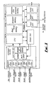
- FIG. 2 a schematic diagram of the signal paths.
- the forces applied to the boom structure may be sensed by transducer means by measuring the corresponding top cylinder end and bottom cylinder end ram pressure using two pressure transducers 21, 28. These pressure transducers may be of the semi-conductor strain gauge type. These two pressure signals are passed to the analogue to digital converter unit within the central unit, described in detail hereinbelow and shown in Figure 3 in block diagram form, where the analogue signals are converted to digital binary representations for processing by the central processing unit, a component within the central unit. Hereafter referred to as the CPU.
- the boom structure is made up of three telescopic sections. At minimum boom length the top two sections lie within the base section as power, the top two sections extend out each by a certain ratiometric amount determined by crane design beyond the base section extending the total length of the boom.
- This change in length of the boom can be measured using transducer means 23 where the transducer may consist of a mechanical cable drum with an internal spring.
- the cable is attached to the tip of the boom such that any linear motion of the boom results in a corresponding angular rotation of the drum.
- the internal spring maintains tension within the cable and ensures the cable is wrapped onto the drum during retraction of the boom.
- the shaft of the drum is coupled to a rotary potentiometer such that linear motion of the boom is translated into a corresponding proportional signal representative to change of boom length.
- This boom length signal is passed to the analogue to digital converter unit within the central unit for processing to a digital binary representation thereafter to the CPU for processing to a signal representative of actual boom length L.
- Another such device 24 may generate signals representative of the conditions of support for example proximity switches may be used to determine whether outriggers are in their extended position or not and would send a corresponding digital signal to the central unit for correct capacity determination. Such a device is able to detect the presence of ferrous material and appropriately positioned would be able to determine whether the outriggers are in an extended position or not.
- Another such device 25 may be operator controlled such that a coded position switch is chosen to correspond to for example the number of parts of rope that the crane is reeved to or to whether a boom extension is being used, these respective signals are then passed to the central unit to establish the correct capacity for that configuration.
- the central unit consists of : an analogue section which contains instrumentation amplifiers; d.c. amplifiers; filters; an analogue multiplexer for selection between analogue signals and an analogue to digital converter; a control unit which performs selection of functions such as memory decoding; a read/write memory unit for temporary data storage; a permanent memory for storing the CPU instructions representing the program and constant data; programmable memory which one programmed with for example specific calibration data becomes permanent memory; a CPU or central processing unit which performs manipulations on data representing signals such as logical or arithmetical operations or memory manipulations; input and output ports which perform the function of communicating with the display; the operators calibration interface, the terminal, and signalling means such as the operator selectable switches.
- the operators display console 27 consists of means of displaying the current operational signal values, system and crane status, this means can consist of a series of numeric displays which may be of the liquid crystal type; a series of annunciators which may be visual of the illuminated graphic symbol type or audible of the piezo-electrical buzzer type.
- the range of angles, range of lengths and range of loads chosen is dependent on the particular crane but in any case is chosen to be representative of the cranes full operational capability and must include calibration steps at the extreme points of practical operation or capacity.
- the optimum calibration points may be deduced from analysis of the crane manufacturers capacity chart.
- the boom angle, the boom length, the load on hook, the actual radius and any other relevant data are recorded, the radius and load on the hook being inputted manually via the portable computer keyboard.
- the ram areas that the forces act upon and physical dimensions of the crane base structure also are manually entered via the portable computer keyboard to allow calculation of actual force from the top and bottom ram cylinder pressure values and calculation of ram geometry.
- the portable computer will contain a file of calibration data points, it then reverts back to its full power as a portable computer and executes the curve modelling program the result of which is coefficient parameters specific to that crane.
- the modelling program tries to establish any linear dependence between initially, actual radius and its dependent variables, load, angle and length, in other words the actual radius or horizontal distance between the cranes rotating axis and the hook is a function of boom length, boom angle and the load on the hook.
- the number of dimensions this process is carried out for is one plus the number of dependent variables so in the case of radius the modelling is carried out to four dimensions.
- the process is carried out to provide an equation or polynomial formula which equates actual radius on one side of the equation to a sum of products on the dependent variables each multiplied by scalar quantities or the coefficient parameters the quantities determined by the modelling or calibration process.
- This process involves using a least squares fit where a series of calculations is carried out to minimise the sum of the square of the deviations of the predicted points from the calibration data points.
- the third step in the modelling process is the determination of the load function or component of total ram force due to the load on the hook. This is a function of actual load on the hook, boom length and boom angle.
- the load on hook calibration data points are therefore used to determine this relationship and to therefore produce the appropriate load function coefficients.
- These coefficient parameters are also programmed into programmable permanent memory of the CPU for later recall by the operational program.
- the fourth step in the modelling process is to bring together the components contributing to the total ram force and all their dependent variables, in other words to form an equation relating to one side the total ram force to on the other side the component of the total force due to the boom transfer function and the component due to the load on the hook.
- the force component due to the boom transfer function which is boom angle, boom length based, or more strictly with load on the hook it is "actual radius" based which of course is load dependent and with the second component of total ram force which is the load function component which is of course also load dependent.
- the final step in the calibration of a system is the duty chart modelling which aims to express for a particular crane, capacity available as a function of boom angle and boom length for a particular configuration. This allows precise interpolation of capacity utilising crane capacity to a maximum.
- the crane duty chart is entered into the computer as a series of data points the modelling computation produces a set of coefficient parameters for each configuration or page of the crane duty chart. Solution of the resulting polynomial for a particular configuration at a particular boom angle and length is a value representative of the available crane capacity. Again these coefficients are programmed into the programmable permanent memory for later recall by the operational program.
- the system due to its ability to model the aeolotropy of a system in mathematical form, say by application of N-th order polynomials, when applied to a fork lift truck or a front end or bucket loader will after analysis of taken data be able to repeat accurately the function of the machine in mathematical form. This will allow the user to know accurately, for example what weight is in the bucket or on the forks without the necessity of the machine to stop on level ground and place the forks or the bucket in a predetermined position whilst stationary, as is required with conventional apparatus and systems.
Landscapes
- Engineering & Computer Science (AREA)
- Mechanical Engineering (AREA)
- Jib Cranes (AREA)
- Testing And Monitoring For Control Systems (AREA)
Abstract
The monitoring system comprises a number of transducers (21,22,23) which are connected to a central unit in order to measure variables which affect the carrying ability of the load carrier. Memory means is also provided and stores data which defines the inter-relationships between the variables. The data defines the inter-relationships in terms of multi-dimensional surfaces or manifolds with a boundary corresponding to the operational limits of the system. Computing means connected to the transducers (21, 22, 23) and the memory means performs real time calculation of the status of the system by substitution of variable values received from the transducers (21, 22, 23).
Description
- This invention relates to a monitoring system for use with load carriers which may be used for preventing and/or giving warning of overload conditions. The invention may also be used as a weighing device.
- The invention will be particularly described with reference to jib cranes, but is also useful with other load carriers such as tower cranes, container handling equipment, fork lift trucks and front end or bucket loaders.
- The maximum safe load of a given jib crane is determined by a number of factors, such as the load radius, the jib angle to the horizontal, and (in the case of a vehicle mounted crane) the slew angle in relation to the chassis. The relationship between such variables and maximum safe load is complex and usually non-linear. It is necessary to provide the operator with information as to permissible and impermissible lifts.
- One way of doing so is to provide the operator with printed tables of data, but these are both difficult to use and are prone to misinterpretation and error. Various means have therefore been used to provide automatic warning signals.
- All of these make use of well-known forms of transducer to provide signals indicative of position, load, etc., but the processing of these signals has not hitherto been entirely satisfactory.
- It is well known in the prior art that at resolution of complex and non-linear inter-relationships of load, radius and capacity and their corresponding dependent variables is required to correctly model behaviour of load handling equipment. Attempts have been made to achieve this by the application of analogue techniques and look-up techniques where tabulated data sets are placed in memory for retrieval and conditioning. Later techniques attempted to linearly interpolate between the tabulated data to increase resolution. Yet later techniques used non-linear interpolation.
- Whilst systems of this type are an improvement on earlier systems they perform adequately only within certain regions and are not able to model the behaviour of the system because these systems are unable to take into account the dynamic interaction of the variables in real time.
- Accordingly, an object of the present invention is to provide an improved monitoring system for load carriers which is capable of working in real time in a manner which permits utilisation of permissible load/configuration combinations.
- The invention provides a monitoring system for a load carrier, comprising a plurality of transducers connected to measure variables affecting the carrying ability of the load carrier, memory means provided with data defining the inter-relationships between said variables, said data defining said inter-relationships in terms of multi-dimensional surfaces or manifolds, and computing means connected to the transducers and the memory means for real-time calculation of the status of the system by substitution of variable values received from the transducers.
- From another aspect, the invention resides in a method of monitoring a load carrier, comprising providing a multi-dimensional mathematical model of loads and forces within the load carrier, continuously detecting the actual values of variable terms of said model, and performing real-time substitution of said actual values into the model to derive a definition of the status of the system.
- Thus, in the context of a crane, the existent complex non-linear relationships between the angle, length and boom forces of a crane and the inter-relationship of the variables are defined using mathematical models the inter-reaction of which by substitution and elimination can produce a mathematical representation of each and every operation function of the device.
- This formula is made up of components which describe multi-dimensional surfaces or manifolds with fixed boundary points corresponding to the operational limits of the system.
- This approach to calculating operational parameters of the system is distinct from previous methods by using surfaces that by their very nature are continuous and thus resolution is fundamentally infinite whereas previous methods using interpolation, look-up or other techniques using discrete data points give inferior resolution leading to limited accuracy. Hence, the invention enables more accurate definition of the status of the system to be derived. One of the consequences of this is that the system is accurate enough to be used as a weighing system to accurately record the weight of a load and totalise a number of loads.
- The components of this formula can be of the form of a N-th order polynomial where N is a positive integer representing the number of coefficients.
- The general form of this polynomial is:
Z = a + b + c + dx + ex +fy + ...
Where a, b, c, are the coefficient parameters. - In order to fit or model the system on such polynomials sets of coefficients are required, these coefficient parameters are characteristic of the whole surface they relate to and not of any point or area within it. These coefficient sets are determined mathematically from a collection of characteristic data points gathered empirically and representative of the complete operational area and limits of the system. These data points can be determined during a calibration procedure.
- The calibration procedure can consist of a series of steps where the boom is taken through its range of angles and lengths both with no load on the hook and with a range of varying loads on the hook. All necessary data will be logged at each distinct step.
- The logged data will consist.of actual length, actual radius, actual load on the hook and in the case of a pressure lifted boom pressure measurement from the hydraulic lifting ram(s) which will directly relate to forces on the boom.
- Computational means can be used to determine the sets of coefficients from the data points using for example a least-squares fit where a series of calculations is carried out to minimise the sum of the squares of the deviations of the predicted points from the data points.
- The result of the computation will be a formula for the total force on the ram(s) equating to two multi-dimensional polynomials one of which will directly relate to the boom behaviour with no load on the hook which is referred to as the boom transfer function. The other main component in the formula will be a polynomial directly related to the load on the hook referred to as the load function.
- During operation of the crane at any point in time various values are substituted into the formula : sets of coefficients relating to the boom transfer function and to the load function; processed signals relating to length, angle and the force on the rams. The solution to this formula is value representative of load on the hook.
- For a load-handling system where warning signals are required, for example approach to overload as required say in the case of a crane, the manufacturer will have provided a set of safe working loads or capacities dictated by the structural limitations or the tipping moment limitations dependent on the area of operation and must be used in order to determine such an approach to overload. These capacity values for any particular crane, are dependent on boom length, boom angle and on the particular operating configuration. The complex non-linear relationship between angle, length and capacity for any particular configuration can also be represented by a multi-dimensional N-th order polynomial which describes a curve representing the capacity of the crane. Structural capacity and tipping capacity are represented by different areas of the curve. In order to fit the manufacturers capacity values or load chart to the polynomial, mathematical and computational means can be used to determine the coefficient parameters. The solution of the polynomial at any particular length and angle is a value for the capacity of the crane for that configuration. This system has advantages over interpolation method or look-up techniques in that the resolution is infinite thereby maximising crane capacity and therefore utilisation.
- In practice the solution of the polynomial at any length or angle is a value representative of the capacity of the crane. Moreover a system of this type allows continuous evaluation of crane capacity, the value of which is infinitely resolvable.
- The same technique in two dimensions using lower order polynomials can be used to linearise physical transducer signals such as from pressure transducers or from a load tensiometer.
- For a better understanding of the invention and to show how the same be carried into effect, reference will now be made, by way of example to the accompanying drawings, wherein:
- Figure 1 is a side elevational view of a crane;
- Figure 2 is a schematic diagram of the signal paths; and
- Figure 3 is a block diagram of the central unit of the load measuring and limiting system.
- Referring now to the drawings, Figure 1 illustrates a crane consisting of a
truck carrier 11 with a truck driver cab 12, abase structure 13, andboom structure 14 rotatably mounted upon the truck carrier by means of a turntable bearing plate 15. The truck carrier is normally transported upondrivable tyres 16 and operated either upon these tyres or upon outriggers 17. The boom structure is hinged at thebase structure 18 allowing vertical rotation through a boom angle theta. A suitable hoist cable may be rigged from theboom structure 19. The hoist cable is diven by a cable drum mounted at the base of the boom, this cable drum may be hydraulically driven. The boom structure itself is lifted by means of ahydraulic lifting ram 110 attached by pivots at the top end to theboom structure 14 and at the bottom end to thebase structure 11. There exists the means to control the top cylinder end and bottom cylinder end hydraulic lifting ram pressures. By means of increasing the hydraulic pressure in the bottom cylinder end and by decreasing the top cylinder end pressure the ram can be extended, the force thus applied to the boom structure will result in the boom vertical angle increasing. Conversely by means of reducing hydraulic pressure in the cylinder bottom end and by increasing the top cylinder end pressure the ram will retract thus reducing the force applied to the boom structure resulting in a corresponding reduction in the boom vertical angle. - Referring now also to Figure 2 a schematic diagram of the signal paths. The forces applied to the boom structure may be sensed by transducer means by measuring the corresponding top cylinder end and bottom cylinder end ram pressure using two
pressure transducers
RESULTANT FORCE = ( P bottom * A bottom ) - ( P top * A top ) - This vertical boom angle theta may be sensed by angle transducer means 22 consisting of a pendulum weight attached to a potentiometer shaft housed in an oil-filled enclosure. Vertical angular movement of the boom structure results in a corresponding angular rotation of the pendulum acting under gravitational force, the motion damped by the oil, resulting in a corresponding analogue signal representative of boom vertical angle. This signal is passed to the analogue to digital converter unit within the central unit for conversion to a digital binary representation for processing by the CPU to produce a signal for actual boom angle theta.
- The boom structure is made up of three telescopic sections. At minimum boom length the top two sections lie within the base section as power, the top two sections extend out each by a certain ratiometric amount determined by crane design beyond the base section extending the total length of the boom. This change in length of the boom can be measured using transducer means 23 where the transducer may consist of a mechanical cable drum with an internal spring. The cable is attached to the tip of the boom such that any linear motion of the boom results in a corresponding angular rotation of the drum. The internal spring maintains tension within the cable and ensures the cable is wrapped onto the drum during retraction of the boom. The shaft of the drum is coupled to a rotary potentiometer such that linear motion of the boom is translated into a corresponding proportional signal representative to change of boom length. This boom length signal is passed to the analogue to digital converter unit within the central unit for processing to a digital binary representation thereafter to the CPU for processing to a signal representative of actual boom length L.
- There is also provided further signalling means to allow manual and automatic determination of the particular crane operating conditions, one such device may determine the quadrant of operation in order to establish the correct available capacity, that is for a crane operating free-on-wheels and capacities available according to the manufacturers differ for over the front, over the side and over the rear operating areas. This signalling means may take the form of a potentiometric device driven by the rotational movement of the base structure where a signal representative of the quadrant of operating is inputted to the analogue to digital converter unit thereafter to the CPU within the central unit where a signal corresponding to the actual rotational angle of the boom is established. Another such device 24 may generate signals representative of the conditions of support for example proximity switches may be used to determine whether outriggers are in their extended position or not and would send a corresponding digital signal to the central unit for correct capacity determination. Such a device is able to detect the presence of ferrous material and appropriately positioned would be able to determine whether the outriggers are in an extended position or not. Another
such device 25 may be operator controlled such that a coded position switch is chosen to correspond to for example the number of parts of rope that the crane is reeved to or to whether a boom extension is being used, these respective signals are then passed to the central unit to establish the correct capacity for that configuration. - Referring now to Figure 3 a block diagram of the central unit. The central unit consists of : an analogue section which contains instrumentation amplifiers; d.c. amplifiers; filters; an analogue multiplexer for selection between analogue signals and an analogue to digital converter; a control unit which performs selection of functions such as memory decoding; a read/write memory unit for temporary data storage; a permanent memory for storing the CPU instructions representing the program and constant data; programmable memory which one programmed with for example specific calibration data becomes permanent memory; a CPU or central processing unit which performs manipulations on data representing signals such as logical or arithmetical operations or memory manipulations; input and output ports which perform the function of communicating with the display; the operators calibration interface, the terminal, and signalling means such as the operator selectable switches.
- There may also be direct measurement means consisting of for example a load pin 26 which consists of a shaft mounted inside of the jib extension tip pulley wheel where this shaft is internally strain gauged to produce an electrical signal proportional to load on the jib extension hook. This signal is passed to the analogue to digital converter unit for further processing.
- The operators display
console 27 consists of means of displaying the current operational signal values, system and crane status, this means can consist of a series of numeric displays which may be of the liquid crystal type; a series of annunciators which may be visual of the illuminated graphic symbol type or audible of the piezo-electrical buzzer type. - All of the calibration procedures may be carried out in the field. Initially a load measuring and safety system with the basic program in read only permanent memory is installed on a crane with the relevant transducers and hardware (Figure 2). Actual boom length and actual boom angle is established through empirical measurement and is calibrated by adjusting the gain of the corresponding amplifier in order to be displayed correctly. A portable computer operating VDU terminal emulation software in order to provide a human interface is connected via the serial RS232 port to the load measuring and safety system. This allows the inputting of data to the safety system via the computer keyboard and the display of safety system data via the computer monitor through appropriate communications software. The load measuring and safety system now controls a data gathering routine where the crane is taken through a series of boom lengths and boom angles initially with no load on the hook thereafter with known loads. The range of angles, range of lengths and range of loads chosen is dependent on the particular crane but in any case is chosen to be representative of the cranes full operational capability and must include calibration steps at the extreme points of practical operation or capacity. The optimum calibration points may be deduced from analysis of the crane manufacturers capacity chart. At each stop the ram pressures, the boom angle, the boom length, the load on hook, the actual radius and any other relevant data are recorded, the radius and load on the hook being inputted manually via the portable computer keyboard. The ram areas that the forces act upon and physical dimensions of the crane base structure also are manually entered via the portable computer keyboard to allow calculation of actual force from the top and bottom ram cylinder pressure values and calculation of ram geometry. Once the data gathering procedure has been completed the portable computer will contain a file of calibration data points, it then reverts back to its full power as a portable computer and executes the curve modelling program the result of which is coefficient parameters specific to that crane. The modelling program tries to establish any linear dependence between initially, actual radius and its dependent variables, load, angle and length, in other words the actual radius or horizontal distance between the cranes rotating axis and the hook is a function of boom length, boom angle and the load on the hook. The actual radius change with boom bending especially with long boom lengths and heavy hook loads, this effect lessens with increasing boom angle. The number of dimensions this process is carried out for is one plus the number of dependent variables so in the case of radius the modelling is carried out to four dimensions. The process is carried out to provide an equation or polynomial formula which equates actual radius on one side of the equation to a sum of products on the dependent variables each multiplied by scalar quantities or the coefficient parameters the quantities determined by the modelling or calibration process. The general form of this polynomial in three dimensions is:
Z = a + bx + cy + dxx + exy + fyy + ...
Where a, b, c, etc., are the coefficient parameters and x and y are the dependent variables. This process involves using a least squares fit where a series of calculations is carried out to minimise the sum of the square of the deviations of the predicted points from the calibration data points. The process can be carried out to increasing levels of accuracy depending on the number of coefficients the curve or surface is modelled to, thus N-th order accuracy requires N in number of coefficient parameters where N is a positive integer. These coefficient parameters distinct to that particular crane are then stored in programmable memory by use of a short programming algorithm. These coefficient parameters can then be recalled by the CPU when an actual radius value is required to be calculated, by simple substitution of the coefficients and the operational values of load, boom angle and boom length simple arithmetic then produces the result. - The second step in the modelling process is to determine the component of force in the rams due to the boom structure itself. That is the total resultant force applied by the ram can be expressed by the following general form:

- The component due to the boom structure is a function of boom angle and boom length for any particular crane with no load on the hook. Or more strictly taking boom bending into account the boom component is a function of angle, length and actual radius. Thus the no load calibration data points are used to determine the coefficient parameters related to the boom no load characteristics or hereafter described as the boom transfer function. The component of force due to the load on the hook will be described hereafter. Again a specific set of coefficient parameters are determined from the no load calibration data points to a required level of accuracy determined by the number of coefficients. The boom transfer coefficients relate to an equation one side of which is the component of total force in the ram due to the boom structure only the other side of the equation is a sum of products of coefficient parameters and boom length and boom angle values. These coefficient parameters are also programmed into the programmable permanent memory of the CPU.
- The third step in the modelling process is the determination of the load function or component of total ram force due to the load on the hook. This is a function of actual load on the hook, boom length and boom angle. The load on hook calibration data points are therefore used to determine this relationship and to therefore produce the appropriate load function coefficients. These coefficient parameters are also programmed into programmable permanent memory of the CPU for later recall by the operational program.
- The fourth step in the modelling process is to bring together the components contributing to the total ram force and all their dependent variables, in other words to form an equation relating to one side the total ram force to on the other side the component of the total force due to the boom transfer function and the component due to the load on the hook. Within this formula though there is an interdependence between the force component due to the boom transfer function which is boom angle, boom length based, or more strictly with load on the hook it is "actual radius" based which of course is load dependent and with the second component of total ram force which is the load function component which is of course also load dependent. Therefore computational means is required within the operational program to carry out a series of iterations to evaluate load on the hook from an initial estimate of load and through repeatedly substituting each more accurate load estimate into the predetermined formulae for load function and actual radius. This simultaneous solution of the component formulae produces an accurate value for load on the hook which satisfies both polynomial components of the total ram force equation.
- The final step in the calibration of a system is the duty chart modelling which aims to express for a particular crane, capacity available as a function of boom angle and boom length for a particular configuration. This allows precise interpolation of capacity utilising crane capacity to a maximum. The crane duty chart is entered into the computer as a series of data points the modelling computation produces a set of coefficient parameters for each configuration or page of the crane duty chart. Solution of the resulting polynomial for a particular configuration at a particular boom angle and length is a value representative of the available crane capacity. Again these coefficients are programmed into the programmable permanent memory for later recall by the operational program.
- Once the crane load measuring and safety system has been calibrated and the relevant data programmed into the CPU memory the portable computer can be removed to leave a stand-alone system consisting of the angle and length transducer means, the selection means both manual and automatic, the central unit and the operators display and warning console. A typical cycle of operation of the load measuring system can be described by following the outline sequence of operations programmed in the permanent memory of the CPU.
- The first operation is for the central unit to undergo a functionality test to ensure the integrity of the system this may include confirming the presence of the boom components and ensuring the functionality of the alarm means. The next step is for the control unit to select the length channel on the analogue multiplexer, this presents the analogue signal representation of length to the analogue to digital converter and a conversion is initiated. On completion of the conversion the binary value is checked to ensure it lies within an acceptable range it is then processed to a signal representative of actual length. This signal is temporarily stored in read/write memory for later usage.
- The next operation is for the control unit to select in sequence, the angle and the top and bottom ram pressures, these are in turn converted to binary values and checked for acceptable limits, processed to signals for actual angle and top and bottom ram force values respectively, then temporarily store in read/write memory.
- The next operation is to determine the actual operating configuration of the crane by reading the selecting switches and sensors to determine whether the outriggers are in or out; the number of parts of line the crane is reeved to; the quadrant of operation; and any other physical situation which may have a bearing on the capacity of the crane in other words the particular set of capacity coefficients are retrieved from programmable permanent memory for that particular operating configuration. The capacity polynomial is then evaluated by substitution of the coefficient parameters and the actual values for boom angle and boom length previously calculated. The result of this arithmetic computation is a value for actual capacity for later use in display and when evaluating percentage capacity.
- The next operation is to calculate the load on the hook from ram pressure measurements, boom angle, boom length values and the predetermined coefficients relating to the boom transfer function and the load function. The component of force due to the load is the total value of ram force minus the boom transfer component of force. As previously stated the boom transfer component of force is actual radius dependent which is in turn load dependent and at this point in time load is an unknown quantity. Therefore the evaluation of the boom transfer function force component is initially carried out using the theoretical value for radius ignoring boom bending effects. The load function is then equated to the remainder of the ram force value and the equation is solved to produce an initial approximate value for load. This value is then used to produce a value of actual radius which is in turn used to revise the boom transfer function component of force. This revised boom transfer component value produces a more accurate value for the load function which is again evaluated to produce a more accurate load value. This series of iterations, simultaneously solving the boom transfer function and the load function, is repeated many times, each evaluation producing a more accurate load value, to the eventual required accuracy.
- As a result of the system's increased accuracy over conventional systems, the system can be used as a totaliser, for example on offshore platforms where deck loading is a significant factor and is monitored daily. The system when applied to a crane can record accurately the weights of up lifts and back lifts and hold these values with other relevant information manually or automatically entered in the memory for easy retrieval.
- The system due to its ability to model the aeolotropy of a system in mathematical form, say by application of N-th order polynomials, when applied to a fork lift truck or a front end or bucket loader will after analysis of taken data be able to repeat accurately the function of the machine in mathematical form. This will allow the user to know accurately, for example what weight is in the bucket or on the forks without the necessity of the machine to stop on level ground and place the forks or the bucket in a predetermined position whilst stationary, as is required with conventional apparatus and systems.
- The final stage in the operation cycle is to compare the load value with the capacity value and to produce a warning signal if the load value exceeds a predetermined percentage of the capacity value. At this stage operational values such as load, angle and length may be passed to the operators console for display.
- Modifications and improvements may be incorporated without parting from the scope of the invention.
Claims (22)
1. A monitoring system for a load carrier, comprising a plurality of transducers connected to measure variables affecting the carrying ability of the load carrier, memory means provided with data defining the inter-relationships between said variables, said data defining said inter-relationships in terms of multi-dimensional surfaces or manifolds, and computing means connected to the transducers and the memory means for real-time calculation of the status of the system by substitution of variable values received from the transducers.
2. A monitoring system according to Claim 1, the system further comprising indicating means to indicate the status of the system.
3. A monitoring system according to Claim 2, wherein the multi-dimensional surfaces or manifolds have a boundary corresponding to the operational limits of the system.
4. A monitoring system according to Claim 3, wherein the indicating means comprises a warning signal to indicate when at least one operational limit of the system is within a predetermined limit of the status of the system.
5. A monitoring system according to Claim 4, wherein the warning signal comprises an audible alarm.
6. A monitoring system according to any of the preceding claims, wherein at least one of the transducers is an angle transducer.
7. A monitoring system according to any of the preceding claims, wherein at least one of the transducers is a length transducer.
8. A monitoring system according to any of the preceding claims, wherein at least one of the transducers is a pressure transducer.
9. A method of monitoring a load carrier, comprising providing a multi-dimensional mathematical model of loads and forces within the load carrier, continuously detecting the actual values of variable terms of said model, and performing real-time substitution of said actual values into the model to derive a definition of the status of the system.
10. A method according to Claim 9, wherein the multi-dimensional mathematical model describes multi-dimensional surfaces or manifolds.
11. A method according to any of Claim 9 or Claim 10, wherein the multi-dimensional mathematical model comprises fixed boundary points which correspond to the operational limits of the system.
12. A method according to any of Claims 9 to 11, wherein the multi-dimensional mathematical model is in the form of a N-th order polynomial.
13. A method according to Claim 12, wherein coefficients of the N-th dimensional polynomial are determined mathematically from a collection of characteristic data points gathered empirically and representative of the complete operational area of the system.
14. A method according to Claim 13, wherein the coefficients are determined from the data points using a least squares analysis.
15. A method according to Claim 13 or Claim 14, wherein the data points are determined during a calibration procedure.
16. A method according to Claim 15, wherein the calibration procedure comprises a series of steps in which the load carrier is taken through its range of possible orientations with no load and with a range of variable loads on the load carrier.
17. A method according to Claim 16, wherein all the necessary data is logged at each distinct step.
18. A method according to Claim 17, wherein the log data comprises actual length, actual radius and actual load.
19. A method according to Claim 17 or Claim 18, wherein the log data further comprises pressure measurements.
20. A method according to Claim 16, wherein the load carrier is a crane and wherein the series of steps comprises taking the boom through its range of angles and lengths with no load on the hook and with a range of varying loads on the hook.
21. A method according to any of Claims 9 to 19, wherein the load carrier is a crane.
22. A method according to Claim 21, wherein the multi-dimensional mathematical model defines the relationships between the angle, length and beam forces of the crane.
Applications Claiming Priority (2)
| Application Number | Priority Date | Filing Date | Title |
|---|---|---|---|
| GB888818074A GB8818074D0 (en) | 1988-07-29 | 1988-07-29 | Monitoring system for load carriers |
| GB8818074 | 1988-07-29 |
Publications (2)
| Publication Number | Publication Date |
|---|---|
| EP0353099A2 true EP0353099A2 (en) | 1990-01-31 |
| EP0353099A3 EP0353099A3 (en) | 1991-04-17 |
Family
ID=10641305
Family Applications (1)
| Application Number | Title | Priority Date | Filing Date |
|---|---|---|---|
| EP19890307719 Withdrawn EP0353099A3 (en) | 1988-07-29 | 1989-07-28 | Monitoring system for load carriers |
Country Status (3)
| Country | Link |
|---|---|
| EP (1) | EP0353099A3 (en) |
| AU (1) | AU3909889A (en) |
| GB (1) | GB8818074D0 (en) |
Cited By (13)
| Publication number | Priority date | Publication date | Assignee | Title |
|---|---|---|---|---|
| EP0470289A1 (en) * | 1990-08-10 | 1992-02-12 | ABUS Kransysteme GmbH & Co. KG. | Arrangement for executing maintenance and mounting tasks in crane arrangement |
| EP0535339A1 (en) * | 1991-10-02 | 1993-04-07 | Jlg Industries, Inc. | Load moment indicator system |
| EP1151958A2 (en) * | 2000-04-28 | 2001-11-07 | Hiab AB | Hydraulic crane |
| WO2003064311A1 (en) * | 2001-11-28 | 2003-08-07 | Højbjerg Maskinfabrik A/S | Load control system, preferably for boom cranes |
| EP1477452A1 (en) * | 2003-05-12 | 2004-11-17 | FASSI GRU IDRAULICHE S.p.A. | Process and device for detecting weight applied on a crane arm |
| WO2008143584A1 (en) * | 2007-05-23 | 2008-11-27 | Cargotec Patenter Ab | Hydraulic crane and a method for regulating the maximum allowed working pressure in such a crane |
| EP2145852A1 (en) * | 2008-07-16 | 2010-01-20 | Manitowoc Crane Companies, Inc. | Load monitoring and control system with selective boom-up lockout |
| ITBO20090588A1 (en) * | 2009-09-16 | 2011-03-17 | A M A S P A | OPERATING MACHINE |
| CN104495658A (en) * | 2014-12-31 | 2015-04-08 | 中联重科股份有限公司 | Debugging method, device and system for moment limiter of crane |
| WO2018068071A1 (en) * | 2016-10-14 | 2018-04-19 | Palfinger Europe Gmbh | Method for determining a load, controller for a hydraulic lifting device for carrying out a method of this type |
| CN110422779A (en) * | 2019-08-29 | 2019-11-08 | 山西五建集团有限公司 | A kind of derrick crane tool security monitoring and alarm system |
| US11142442B2 (en) | 2017-02-10 | 2021-10-12 | Arrow Acquisition, Llc | System and method for dynamically controlling the stability of an industrial vehicle |
| EP3313771B1 (en) | 2015-06-24 | 2021-12-08 | Palfinger AG | Crane controller |
Citations (5)
| Publication number | Priority date | Publication date | Assignee | Title |
|---|---|---|---|---|
| DE3019385A1 (en) * | 1979-05-18 | 1980-11-27 | Coles Cranes Ltd | CRANE WITH DATA PROCESSING SYSTEM |
| DE3341287A1 (en) * | 1982-12-02 | 1984-06-07 | Krüger GmbH & Co KG, 4300 Essen | LOAD MONITORING DEVICE FOR A JET CRANE |
| US4456093A (en) * | 1981-06-16 | 1984-06-26 | Interstate Electronics Corp. | Control system for aerial work platform machine and method of controlling an aerial work platform machine |
| WO1985005614A1 (en) * | 1984-06-01 | 1985-12-19 | Dr.-Ing. Ludwig Pietzsch Gmbh & Co | Monitoring and control system for jib-cranes |
| EP0285710A1 (en) * | 1987-03-06 | 1988-10-12 | 3B6 sistemi elettro-idraulici s.n.c. | Arm range and/or moment limiting device for elevator platforms |
-
1988
- 1988-07-29 GB GB888818074A patent/GB8818074D0/en active Pending
-
1989
- 1989-07-28 EP EP19890307719 patent/EP0353099A3/en not_active Withdrawn
- 1989-07-28 AU AU39098/89A patent/AU3909889A/en not_active Abandoned
Patent Citations (5)
| Publication number | Priority date | Publication date | Assignee | Title |
|---|---|---|---|---|
| DE3019385A1 (en) * | 1979-05-18 | 1980-11-27 | Coles Cranes Ltd | CRANE WITH DATA PROCESSING SYSTEM |
| US4456093A (en) * | 1981-06-16 | 1984-06-26 | Interstate Electronics Corp. | Control system for aerial work platform machine and method of controlling an aerial work platform machine |
| DE3341287A1 (en) * | 1982-12-02 | 1984-06-07 | Krüger GmbH & Co KG, 4300 Essen | LOAD MONITORING DEVICE FOR A JET CRANE |
| WO1985005614A1 (en) * | 1984-06-01 | 1985-12-19 | Dr.-Ing. Ludwig Pietzsch Gmbh & Co | Monitoring and control system for jib-cranes |
| EP0285710A1 (en) * | 1987-03-06 | 1988-10-12 | 3B6 sistemi elettro-idraulici s.n.c. | Arm range and/or moment limiting device for elevator platforms |
Cited By (18)
| Publication number | Priority date | Publication date | Assignee | Title |
|---|---|---|---|---|
| EP0470289A1 (en) * | 1990-08-10 | 1992-02-12 | ABUS Kransysteme GmbH & Co. KG. | Arrangement for executing maintenance and mounting tasks in crane arrangement |
| EP0535339A1 (en) * | 1991-10-02 | 1993-04-07 | Jlg Industries, Inc. | Load moment indicator system |
| EP1151958A2 (en) * | 2000-04-28 | 2001-11-07 | Hiab AB | Hydraulic crane |
| EP1151958A3 (en) * | 2000-04-28 | 2004-12-22 | Hiab AB | Hydraulic crane |
| WO2003064311A1 (en) * | 2001-11-28 | 2003-08-07 | Højbjerg Maskinfabrik A/S | Load control system, preferably for boom cranes |
| EP1477452A1 (en) * | 2003-05-12 | 2004-11-17 | FASSI GRU IDRAULICHE S.p.A. | Process and device for detecting weight applied on a crane arm |
| WO2008143584A1 (en) * | 2007-05-23 | 2008-11-27 | Cargotec Patenter Ab | Hydraulic crane and a method for regulating the maximum allowed working pressure in such a crane |
| US7677401B2 (en) | 2008-07-16 | 2010-03-16 | Manitowoc Crane Companies, Inc. | Load monitoring and control system with selective boom-up lockout |
| EP2145852A1 (en) * | 2008-07-16 | 2010-01-20 | Manitowoc Crane Companies, Inc. | Load monitoring and control system with selective boom-up lockout |
| ITBO20090588A1 (en) * | 2009-09-16 | 2011-03-17 | A M A S P A | OPERATING MACHINE |
| CN104495658A (en) * | 2014-12-31 | 2015-04-08 | 中联重科股份有限公司 | Debugging method, device and system for moment limiter of crane |
| EP3313771B1 (en) | 2015-06-24 | 2021-12-08 | Palfinger AG | Crane controller |
| WO2018068071A1 (en) * | 2016-10-14 | 2018-04-19 | Palfinger Europe Gmbh | Method for determining a load, controller for a hydraulic lifting device for carrying out a method of this type |
| JP2019530627A (en) * | 2016-10-14 | 2019-10-24 | パルフィンガー アクチエンゲゼルシャフトPalfinger Ag | Method for determining the load and control device for a hydraulic lifting device for carrying out such a method |
| RU2714833C1 (en) * | 2016-10-14 | 2020-02-19 | Палфингер Аг | Method of determining load, control unit for hydraulic lifting device for implementation of such method |
| AU2017342185B2 (en) * | 2016-10-14 | 2020-03-12 | Palfinger Ag | Method for determining a load, controller for a hydraulic lifting device for carrying out a method of this type |
| US11142442B2 (en) | 2017-02-10 | 2021-10-12 | Arrow Acquisition, Llc | System and method for dynamically controlling the stability of an industrial vehicle |
| CN110422779A (en) * | 2019-08-29 | 2019-11-08 | 山西五建集团有限公司 | A kind of derrick crane tool security monitoring and alarm system |
Also Published As
| Publication number | Publication date |
|---|---|
| AU3909889A (en) | 1990-02-01 |
| EP0353099A3 (en) | 1991-04-17 |
| GB8818074D0 (en) | 1988-09-01 |
Similar Documents
| Publication | Publication Date | Title |
|---|---|---|
| AU648367B2 (en) | A method for measuring the weight of a suspended load | |
| EP0353099A2 (en) | Monitoring system for load carriers | |
| EP0229083B1 (en) | The determining of the amount of material delivered each operational cycle of a shovel loader | |
| US8370031B2 (en) | Device for measuring a load at the end of a rope wrapped over a rod | |
| AU753875B2 (en) | Load weighing system for heavy machinery | |
| US5160055A (en) | Load moment indicator system | |
| EP2668476B1 (en) | Method in the check weighing of a weighing system and software product and arrangement in the check weighing of a weighing system and materials handling equipment | |
| CA2082930A1 (en) | Dynamic payload monitor | |
| CN109736372B (en) | Digger loader capable of weighing and preventing overload | |
| JPH05502292A (en) | Apparatus and method for monitoring payloads | |
| CN111847335B (en) | Overhead working platform truck, bearing monitoring method, bearing monitoring device and storage medium | |
| CN113124972A (en) | Excavator material weighing method and system | |
| US3853001A (en) | Crane load measuring means | |
| GB2103811A (en) | Measuring the loading of hydraulic excavators or the like | |
| JPH0439880Y2 (en) | ||
| JPH0459572B2 (en) | ||
| GB2571358A (en) | A conveyor system with weighing capability | |
| JPH0435579B2 (en) | ||
| EP1477452B1 (en) | Process and device for detecting weight applied on a crane arm | |
| US20230221200A1 (en) | System and method for determining load on winch hook | |
| CN117029984A (en) | Electric shovel weighing method and device | |
| JPH049244B2 (en) | ||
| JPS6343318B2 (en) |
Legal Events
| Date | Code | Title | Description |
|---|---|---|---|
| PUAI | Public reference made under article 153(3) epc to a published international application that has entered the european phase |
Free format text: ORIGINAL CODE: 0009012 |
|
| AK | Designated contracting states |
Kind code of ref document: A2 Designated state(s): AT BE CH DE ES FR GB GR IT LI LU NL SE |
|
| PUAL | Search report despatched |
Free format text: ORIGINAL CODE: 0009013 |
|
| AK | Designated contracting states |
Kind code of ref document: A3 Designated state(s): AT BE CH DE ES FR GB GR IT LI LU NL SE |
|
| STAA | Information on the status of an ep patent application or granted ep patent |
Free format text: STATUS: THE APPLICATION IS DEEMED TO BE WITHDRAWN |
|
| 18D | Application deemed to be withdrawn |
Effective date: 19911018 |