EP0352615A1 - Closure device for a container with a dispensing lip, in particular a glue container - Google Patents
Closure device for a container with a dispensing lip, in particular a glue container Download PDFInfo
- Publication number
- EP0352615A1 EP0352615A1 EP89113225A EP89113225A EP0352615A1 EP 0352615 A1 EP0352615 A1 EP 0352615A1 EP 89113225 A EP89113225 A EP 89113225A EP 89113225 A EP89113225 A EP 89113225A EP 0352615 A1 EP0352615 A1 EP 0352615A1
- Authority
- EP
- European Patent Office
- Prior art keywords
- container
- spatula
- closure
- adhesive
- sealing
- Prior art date
- Legal status (The legal status is an assumption and is not a legal conclusion. Google has not performed a legal analysis and makes no representation as to the accuracy of the status listed.)
- Withdrawn
Links
Images

Classifications
-
- B—PERFORMING OPERATIONS; TRANSPORTING
- B43—WRITING OR DRAWING IMPLEMENTS; BUREAU ACCESSORIES
- B43K—IMPLEMENTS FOR WRITING OR DRAWING
- B43K23/00—Holders or connectors for writing implements; Means for protecting the writing-points
- B43K23/08—Protecting means, e.g. caps
- B43K23/12—Protecting means, e.g. caps for pens
-
- B—PERFORMING OPERATIONS; TRANSPORTING
- B65—CONVEYING; PACKING; STORING; HANDLING THIN OR FILAMENTARY MATERIAL
- B65D—CONTAINERS FOR STORAGE OR TRANSPORT OF ARTICLES OR MATERIALS, e.g. BAGS, BARRELS, BOTTLES, BOXES, CANS, CARTONS, CRATES, DRUMS, JARS, TANKS, HOPPERS, FORWARDING CONTAINERS; ACCESSORIES, CLOSURES, OR FITTINGS THEREFOR; PACKAGING ELEMENTS; PACKAGES
- B65D51/00—Closures not otherwise provided for
- B65D51/24—Closures not otherwise provided for combined or co-operating with auxiliary devices for non-closing purposes
-
- B—PERFORMING OPERATIONS; TRANSPORTING
- B43—WRITING OR DRAWING IMPLEMENTS; BUREAU ACCESSORIES
- B43M—BUREAU ACCESSORIES NOT OTHERWISE PROVIDED FOR
- B43M11/00—Hand or desk devices of the office or personal type for applying liquid, other than ink, by contact to surfaces, e.g. for applying adhesive
Definitions
- the invention relates to a device for closing a container with a dosing tip, in particular a waste container, with a closure enclosing the dosing tip, which can be placed on the container, with a sealing cap which can be placed on the dosing tip and with a sealing nose which engages in the opening of the dosing tip.
- Such devices for closing containers serve to seal a container airtight after use so that the air-sensitive substance in the container, in particular flowable adhesive, does not dry out.
- the sealing effect is achieved in that the device has a sealing nose which engages in the dosing tip of the container and which ensures a tight seal of the dosing tip.
- a disadvantage of the containers with closing devices designed in this way is, however, that the substance in the container, in particular adhesive, can only be expressed in a punctiform manner by the metering tip.
- the adhesive in order to obtain a perfect adhesive surface, for example, it is necessary to apply the adhesive evenly to the adhesive surface, which is very difficult to achieve with a punctiform application.
- a uniform distribution can only be achieved by spreading the applied adhesive evenly with an additional spreading element.
- an additional element is required for this, which is not always available in daily use and, especially after use, that is to say after coming into contact with adhesive, brings with it removal problems, since it cannot be easily removed from the spreading surface due to adhesive residues.
- the object of the invention is to provide a solution which enables a uniformly planar distribution of materials, in particular adhesives, which are applied in a punctiform manner from containers in an easily manageable manner without additional external devices and without removal problems.
- spatula is pivotably arranged on the closure by means of at least one hinge.
- the spatula can then, for example, be folded into the interior of the closure in the starting position and can be folded out of the closure after removal.
- a particularly preferred embodiment of the invention is characterized in that two opposing side walls extending beyond the sealing cap are formed on the closure in the area of the sealing cap, the spatula being arranged in the area between the free ends of the side walls. It is particularly advantageous if the spatula has a hinge two flaps pivotable about the transverse axis is provided, each flap being arranged on the inner surface of the respective side wall via a further hinge.
- This embodiment represents a particularly expedient embodiment of the invention, the spatula can be folded out from the container before the closure is removed by slightly pulling the opposite side walls apart or, if necessary, also pulling on the spatula itself. After use, the spatula can then be returned to the folded starting position without hard contact, which prevents the spatula from coming into contact with objects unintentionally.
- closure is in one piece and the hinges are (are) designed as film hinges.
- the closure can in particular be manufactured as a one-piece injection molded part, which simplifies production and makes it particularly cost-effective.
- ribs are formed in the side walls in the region of the spatula.
- the invention advantageously also provides that a suspension is arranged at the free end of a side wall which can be integrated into the side wall.
- a bottle-shaped adhesive container 1 which is only shown in its upper end region, has a metering tip 2 with a metering opening 3.
- a tapering area 4 and an annular groove 5 are formed, which is provided for engaging a closure 6 for the container.
- This closure 6 has a cap-shaped area 7, at the opening of which an inner annular bead 8 is formed, which serves to snap the closure 6 into the groove 5 of the container 1.
- a sealing cap 9 is formed with a sealing lug 10, which engages in the metering opening 3 of the metering tip 2 in the attached state.
- the closure 6 also has two opposing side walls 11, 12, which are molded onto the cap-shaped region 7 and extend in the region of the sealing cap 9 and beyond.
- two opposite film hinges 15, 16 are formed on the inner surfaces, on each of which a tab 17, 18 is pivotably arranged. The ends of these tabs 17, 18 are connected to a spatula 21 via two further film hinges 19, 20.
- External ribs 22, 23 are formed in the side walls 11, 12 in the area of the spatula for reinforcement.
- the side wall 12 is longer compared to the side wall 11, a suspension eye 24 (FIG. 3) being formed at the free end 14 of the side wall 12.
- the closure 6 is pulled off the container 1, so that the metering opening 3 of the metering tip 2 is released.
- the adhesive can then be applied in a customary manner by exerting pressure on the container 1 in a punctiform manner through the metering opening 3 onto the adhesive surface to be treated.
- the spatula 21 integrated in the closure 6 can be used to evenly spread the adhesive.
- the spatula 21 is unfolded. This unfolding takes place by pulling apart the side walls 11, 12 in the area of the spatula 21, as a result of which the tabs 17, 18 are pivoted via the film hinges 15 and 16. At the same time, the film hinges 19 and 20 of the spatula 21 thereby fold out upwards.
- the closure 6 now serves as a spreading element for the dispensed adhesive.
- the closure 6 is preferably held with one hand in the unfolded position of the spatula 21 shown in FIG. 2 in the region of the ribs 22 and 23 and can thus be carried out with the spatula 21 spread the adhesive evenly.
- the side walls 11, 12 are again pulled apart in the region of the ribs 22 and 23, so that the tabs 17, 18 and the spatula 21 are again folded back into the closure 6 in the starting position shown in FIG. 1.
- This folding process can take place without touching the spatula 21 itself, so that no adhesive residues can reach the user's hand.
- the spatula 21 is then again in the position shown in Fig. 1, i. H. folded in such a way that an unintentional contact of the spatula 21 with other objects is excluded.
- the closure 6 is then placed again on the container 1.
- the adhesive container 1 can then be transported in a briefcase or the like, for example, without the risk that adhesive residues located on the spatula 21 can get onto other objects carried in the pocket.
- the container 1 with the closure 6 can also be suspended at a suitable point in the side wall 12 by means of the suspension eye 24.
- the invention is not limited to the exemplary embodiments shown in the drawing. Further refinements of the invention are possible without leaving the basic idea.
- a different arrangement of the spatula on the closure is of course also possible, for example, the spatula can be arranged on the closure via a simple hinge joint and the like. More.
Landscapes
- Engineering & Computer Science (AREA)
- Mechanical Engineering (AREA)
- Closures For Containers (AREA)
Abstract
Description
Die Erfindung betrifft eine Vorrichtung zum Verschließen eines Behälters mit Dosierspitze, insbesondere eines Kelbstoffbehälters, mit einem die Dosierspitze umschließenden, auf den Behälter aufsetzbaren Verschluß mit einer auf die Dosierspitze aufsetzbaren Dichtkappe mit einer in die Öffnung der Dosierspitze eingreifenden Dichtnase.The invention relates to a device for closing a container with a dosing tip, in particular a waste container, with a closure enclosing the dosing tip, which can be placed on the container, with a sealing cap which can be placed on the dosing tip and with a sealing nose which engages in the opening of the dosing tip.
Derartige Vorrichtungen zum Verschließen von Behältern sind bekannt. Sie dienen dazu, eine Behälter nach dem Gebrauch luftdicht zu verschließen damit der im Behälter befindliche luftempfindliche Stoff, insbesondere fließfähige Klebstoff, nicht austrocknet. Dabei wird die Dichtwirkung dadurch erzielt, daß die Vorrichtung eine in die Dosierspitze des Behälters eingreifende Dichtnase aufweist, welche einen dichten Abschluß der Dosierspitze gewährleistet.Such devices for closing containers are known. They serve to seal a container airtight after use so that the air-sensitive substance in the container, in particular flowable adhesive, does not dry out. The sealing effect is achieved in that the device has a sealing nose which engages in the dosing tip of the container and which ensures a tight seal of the dosing tip.
Nachteilig bei den derart ausgebildeten Behältern mit Verschließvorrichtungen ist aber, daß der im Behälter befindliche Stoff, insbesondere Klebstoff, nur punktförmig durch die Dosierspitze ausgedrückt werden kann. Um jedoch beispielsweise eine einwandfreie Klebefläche zu erhalten, ist es notwendig, den Klebstoff gleichmäßig auf die Klebe fläche aufzubringen, was durch ein punktförmiges Aufbringen nur sehr schwierig zu erreichen ist. Eine gleichmäßige Verteilung kann nur dadurch erreicht werden, daß mit einem zusätzlichen Verstreichelement der ausgetragene Klebstoff gleichmäßig verstrichen wird. Hierzu is allerdings ein zusätzliches Element notwendig, das im täglichen Gebrauch nicht immer zur Verfügung steht und vor allem nach dem Gebrauch, d. h. nach dem Inkontaktkommen mit Klebstoff, Beseitigungsprobleme mit sich bringt, da es aufgrund von Kleberesten an der Verstreichfläche nicht einfach abgelegt werden kann.A disadvantage of the containers with closing devices designed in this way is, however, that the substance in the container, in particular adhesive, can only be expressed in a punctiform manner by the metering tip. However, in order to obtain a perfect adhesive surface, for example, it is necessary to apply the adhesive evenly to the adhesive surface, which is very difficult to achieve with a punctiform application. A uniform distribution can only be achieved by spreading the applied adhesive evenly with an additional spreading element. However, an additional element is required for this, which is not always available in daily use and, especially after use, that is to say after coming into contact with adhesive, brings with it removal problems, since it cannot be easily removed from the spreading surface due to adhesive residues.
Aufgabe der Erfindung ist die Schaffung einer Lösung, welche auf leicht handhabbare Weise ohne zusätzliche externe Einrichtungen und ohne Beseitigungsprobleme eine gleichmäßige flächige Verteilung von punktförmig aus Behältern ausgebrachten Stoffen, insbesondere Klebstoffen ermöglicht.The object of the invention is to provide a solution which enables a uniformly planar distribution of materials, in particular adhesives, which are applied in a punctiform manner from containers in an easily manageable manner without additional external devices and without removal problems.
Diese Aufgabe wird mit einer Vorrichtung der eingangs bezeichneten Art erfindungsgemäß dadurch gelöst, daß in den Verschluß ein aus diesem ausklappbarer Spachtel integriert ist.This object is achieved according to the invention with a device of the type described in the introduction in that a spatula which can be folded out of it is integrated in the closure.
Mit dieser Vorrichtung kann auf besonders leicht handhabbare Weise punktförmig aus einem Behälter austretender Klebstoff oder dgl. gleichmäßig verteilt werden, ohne daß dazu zusätzliche Einrichtungen notwendig wären. Es muß dazu lediglich nach der Abnahme des Verschlusses ein in den Verschluß integrierter Spachtel ausgeklappt werden, mit dem dann der Klebstoff gleichmäßig flächig verstrichen werden kann. Der Verschluß erfüllt somit eine Doppelfunktion als Dichtungs-und Verstreichelement. Nach dem Auftragen des Klebstoffes kann der mit Klebstoff benetzte Spachtel einfach wieder eingeklappt und der Verschluß entsprechend auf den Behälter aufgesetzt werden, so daß keine Probleme mit der Beseitigung des Spachtels entstehen, d. h. es nicht zu einem ungewünschten Ankleten des Spachtels an umliegenden Gegenständen kommt.With this device, adhesive or the like emerging from a container can be uniformly distributed in a particularly easy-to-handle manner without additional facilities would be necessary for this. It is only necessary to fold out a spatula integrated in the closure after removing the closure, with which the adhesive can then be spread evenly over the entire area. The closure thus fulfills a double function as a sealing and spreading element. After the adhesive has been applied, the spatula wetted with adhesive can simply be folded in again and the closure placed on the container accordingly, so that there are no problems with removing the spatula, ie there is no undesired adherence of the spatula to surrounding objects.
Es ist zweckmäßig, wenn der Spachtel mittels wenigstens eines Scharnieres verschwenkbar am Verschluß angeordnet ist. Der Spachtel kann dann beispielsweise in der Ausgangsstellung in das Innere des Verschlusses eingeklappt sein und nach Abnahme des Verschlusses aus diesem ausgeklappt werden.It is expedient if the spatula is pivotably arranged on the closure by means of at least one hinge. The spatula can then, for example, be folded into the interior of the closure in the starting position and can be folded out of the closure after removal.
Eine besonders bevorzugte Ausführungsform der Erfindung zeichnet sich dadurch aus, daß am Verschluß im Bereich der Dichtkappe zwei gegenüberliegende, sich über die Dichtkappe hinaus erstreckende Seitenwände ausgebildet sind, wobei der Spachtel im Bereich zwischen den freien Enden der Seitenwände angeordnet ist. Dabei ist es besonders vorteilhaft, wenn der Spachtel über je ein Scharnier mit zwei um die Querachse verschwenkbaren Laschen versehen ist, wobei jede Lasche über je ein weiteres Scharnier an der Innenfläche der jeweiligen Seitenwand angeordnet ist. Diese Ausführungsform stellt eine besonders zweckmäßige Ausbildung der Erfindung dar, der Spachtel kann bereits vor dem Abnehmen des Verschlusses vom Behälter ausgeklappt werden, indem die gegenüberliegenden Seitenwände leicht auseinandergezogen werden bzw. ggf. auch am Spachtel selbst gezogen wird. Nach dem Gebrauch kann der Spachtel dann ohne Hardkontakt in die eingeklappte Ausgangsstellung zurückgeführt werden, wodurch verhindert wird, daß der Spachtel ungewollt mit Gegenständen in Berührung kommt.A particularly preferred embodiment of the invention is characterized in that two opposing side walls extending beyond the sealing cap are formed on the closure in the area of the sealing cap, the spatula being arranged in the area between the free ends of the side walls. It is particularly advantageous if the spatula has a hinge two flaps pivotable about the transverse axis is provided, each flap being arranged on the inner surface of the respective side wall via a further hinge. This embodiment represents a particularly expedient embodiment of the invention, the spatula can be folded out from the container before the closure is removed by slightly pulling the opposite side walls apart or, if necessary, also pulling on the spatula itself. After use, the spatula can then be returned to the folded starting position without hard contact, which prevents the spatula from coming into contact with objects unintentionally.
Besonders zweckmäßig ist es, wenn der Verschluß einstückig und die Scharniere als Filmscharniere ausgebildet ist (sind). Dabei kann der Verschluß insbesondere als einteiliges Spritzgußteil gefertigt werden was die Herstellung vereinfacht und besonders kostengünstig macht.It is particularly useful if the closure is in one piece and the hinges are (are) designed as film hinges. The closure can in particular be manufactured as a one-piece injection molded part, which simplifies production and makes it particularly cost-effective.
Zur Verstärkung der Seitenwände, welche durch das Auseinanderziehen beim Ausklappen und Wiedereinklappen des Spachtels überbeansprucht werden können, ist vorgesehen, daß in den Seitenwänden im Bereich des Spachtels Rippen ausgebildet sind.To reinforce the side walls, which can be overstressed by pulling them apart when the spatula is folded out and in again, it is provided that ribs are formed in the side walls in the region of the spatula.
Schließlich sieht die Erfindung vorteilhaft auch vor, daß am freien Ende einer Seitenwand eine Aufhängung angeordnet ist, die in die Seitenwand integriert sein kann. Dadurch kann der gesamte Behälter mit dem Verschluß nach dem Gebrauch auf einfache Weise durch Aufhängen abgelegt werden.Finally, the invention advantageously also provides that a suspension is arranged at the free end of a side wall which can be integrated into the side wall. As a result, the entire container with the closure can be stored in a simple manner by hanging up after use.
Die Erfindung ist nachstehend anhand der Zeichnung beispielsweise näher erläutert. Diese zeigt in:
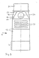
- Fig. 1 in einem Halbschnitt eine auf einen Behälter aufgesetzte erfindungsgemäße Vorrichtung mit eingeklappten Spachtel,
- Fig. 2 dieselbe Vorrichtung ohne Behälter wie in Fig. 1 mit ausgeklappten Spachtel ebenfalls in einem Halbschnitt
- Fig. 3 die Vorrichtung nach Fig. 2 in einer Seitenansicht.
- 1 is a half section of a device according to the invention placed on a container with the spatula folded,
- Fig. 2 shows the same device without a container as in Fig. 1 with the spatula also in a half section
- Fig. 3 shows the device of FIG. 2 in a side view.
Ein flaschenförmiger Klebstoffbehälter 1, der nur in seinem oberen Endbereich dargestellt ist, weist eine Dosierspitze 2 mit Dosieröffnung 3 auf. Im Bereich zwischen der Dosierspitze 2 und dem eingentlichen Behälter ist ein sich verjüngender Bereich 4 und eine ringförmige Nut 5 ausgebildet, welche zum Einrasten eines Verschlusses 6 für den Behälter vorgesehen ist.A bottle-shaped adhesive container 1, which is only shown in its upper end region, has a
Dieser Verschluß 6 weist einen kappenförmigen Bereich 7 auf, an dessen Öffnung eine innenliegende ringförmige Wulst 8 ausgebildet ist, welche zum Einrasten des Verschlusses 6 in die Nut 5 des Behälters 1 dient. Am oberen Ende des kappenförmigen Bereiches 7 ist eine Dichtkappe 9 mit einer Dichtnase 10 ausgebildet, welche im aufgesetzten Zustand in die Dosieröffnung 3 der Dosierspitze 2 eingreift.This
Der Verschluß 6 weist weiterhin zwei sich gegenüberliegende Seitenwände 11,12 auf, welche an den kappenförmigen Bereich 7 angeformt sind und sich in dem Bereich der Dichtkappe 9 und darüber hinaus erstrecken. Im Bereich der freien Enden 13,14 dieser Seitenwände 11,12 sind an den Innenflächen zwei sich gegenüberliegende Filmscharniere 15,16 ausgebildet, an denen verschwenkbar jeweils eine Lasche 17,18 angeordnet ist. Die Enden dieser Laschen 17,18 sind über zwei weitere Filmscharniere 19,20 mit einem Spachtel 21 verbunden.The
In den Seitenwänden 11,12 sind im Bereich des Spachtels 21 außenliegende Rippen 22,23 zur Verstärkung ausgebildet. Außerdem ist die Seitenwand 12 gegenüber der Seitenwand 11 länger ausgeführt, wobei am freien Ende 14 der Seitenwand 12 eine Aufhängeöse 24 (Fig. 3) ausgebildet ist.
Soll nun dem Behälter 1 Klebstoff entnommen werden, so wird der Verschluß 6 vom Behälter 1 abgezogen, so daß die Dosieröffnung 3 der Dosierspitze 2 freigegeben wird. Der Klebstoff kann dann in üblicher Weise durch Druckausübung auf den Behälter 1 punktförmig durch die Dosieröffnung 3 auf die zu behandelnde Klebefläche aufgetragen werden. Wird nun aber eine gleichmäßige Auftragung des Klebers gewünscht, so kann der in den Verschluß 6 integrierte Spachtel 21 zum gleichmäßigen Verstreichen des Klebers verwendet werden. Dazu wird der Spachtel 21 ausgeklappt. Dieses Ausklappen erfolgt durch ein Auseinanderziehen der Seitenwände 11,12 im Bereich des Spachtels 21, wodurch über die Filmscharniere 15 und 16 die Laschen 17,18 verschwenkt werden. Glecihzeitig wird dadurch über die Filmscharniere 19 und 20 der Spachtel 21 nach oben hin ausgeklappt.If adhesive 1 is now to be removed from the container, the
Sobald die Laschen 17,18 weit genug ausgeschwenkt sind, werden die Seitenflächen 11,12 im Bereich der Verstärkungsrippen 22 und 23 wieder zusammengedrückt, so daß die Laschen 17,18 und der Spachtel 21 in die in Fig. 2 dargestellte ausgeklappte Stellung gelangen. In dieser Position des Spachtels 21 dient nun der Verschluß 6 als Verstreichelement für den ausgetragenen Klebstoff. Dazu hält man vorzugsweise mit einer Hand den Verschluß 6 in der in Fig. 2 dargestellten ausgeklappten Stellung des Spachtels 21 im Bereich der Rippen 22 und 23 und kann so mit dem Spachtel 21 den Klebstoff gleichmäßig verstreichen. Nach dem Gebrauch werden wiederum die Seitenwände 11,12 im Bereich der Rippen 22 und 23 auseinandergezogen, so daß die Laschen 17,18 und der Spachtel 21 wiederum in die in Fig. 1 dargestellte Ausgansstellung zurück in den Verschluß 6 eingeklappt werden. Dieser Einklappvorgang kann dabei ohne Berührung des Spachtels 21 selbst erfolgen, so daß keine Klebereste an die Hand des Benutzers gelangen können.As soon as the
Der Spachtel 21 befindet sich dann wiederum in der in Fig. 1 dargestellten Stellung, d. h. derart eingeklappt, daß ein ungewolltes Inberührungkommen des Spachtels 21 mit anderen Gegenständen ausgeschlossen ist. Anschließend wird der Verschluß 6 dann wiederum auf den Behälter 1 aufgesetzt. In diesem Zustand kann dann beispielsweise der Klebstoffbehälter 1 in einer Aktentasche oder dgl. transportiert werden, ohne daß die Gefahr besteht, daß am Spachtel 21 befindliche Klebstoffreste an andere, in der Tasche transportierte Gegenstände geraten. Auch kann der Behälter 1 mit dem Verschluß 6 mittels der Aufhängeöse 24 in der Seitenwand 12 an geeigneter Stelle aufgehängt werden.The
Natürlich ist die Erfindung nicht auf die in der Zeichnung dargestellten Ausführungsbeispiele beschränkt. Weitere Ausgestaltungen der Erfindung sind möglich, ohne den Grundgedanken zu verlassen. So ist selbstverständlich auch eine andere Anordnung des Spachtels am Verschluß möglich, beispielsweise kann der Spachtel über ein einfaches Scharniergelenk am Verschluß angeordnet sein und dgl. mehr.Of course, the invention is not limited to the exemplary embodiments shown in the drawing. Further refinements of the invention are possible without leaving the basic idea. A different arrangement of the spatula on the closure is of course also possible, for example, the spatula can be arranged on the closure via a simple hinge joint and the like. More.
Claims (8)
dadurch gekennzeichnet,
daß in den Verschluß (6) ein aus diesen ausklappbarer Spachtel (21) integriert ist.1.Device for closing a container with a dosing tip, in particular an adhesive container, with a closure which surrounds the dosing tip and can be placed on the container with a sealing cap which can be placed on the dosing tip and has a sealing lug which engages in the opening of the dosing tip.
characterized,
that in the closure (6) a foldable spatula (21) is integrated.
dadurch gekennzeichnet,
daß der Spachtel (21) mittels wenigstens eines Scharnieres verschwenkbar am Verschluß (6) angeordnet ist.2. Device according to claim 1,
characterized,
that the spatula (21) is pivotally arranged on the closure (6) by means of at least one hinge.
dadurch gekennzeichnet,
daß am Verschluß (6) im Bereich der Dichtkappe (9) zwei sich gegenüberliegende, sich über die Dichtkappe (9) hinaus erstreckende Seitenwände (11,12) ausgebildet sind, wobei der Spachtel (21) im Bereich zwischen den freien Enden (13,14) der Seitenwände (11,12) angeordnet ist.3. Device according to claim 1 or 2,
characterized,
that two opposite side walls (11, 12) extending beyond the sealing cap (9) are formed on the closure (6) in the area of the sealing cap (9), the spatula (21) in the area between the free ends (13, 14) of the side walls (11, 12) is arranged.
dadurch gekennzeichnet,
daß der Spachtel (21) über je ein Scharnier (19,20) mit zwei um die Querachse des Spachtels (21) verschwenkbaren Laschen (17,18) versehen ist, wobei jede Lasche (17,18) über je ein weiteres Scharnier (15,16) an der Innenfläche der jeweiligen Seitenwand (11,12) angeordnet ist.4. The device according to claim 3,
characterized,
that the spatula (21) is provided with a hinge (19, 20) with two tabs (17, 18) which can be pivoted about the transverse axis of the spatula (21), each tab (17, 18) with a further hinge (15 , 16) is arranged on the inner surface of the respective side wall (11, 12).
dadurch gekennzeichnet,
daß der Verschluß (6) einstückig und die Scharniere (15,16,19,20) als Filmscharniere ausgebildet ist (sind).5. The device according to claim 2 or one of the following,
characterized,
that the closure (6) is in one piece and the hinges (15, 16, 19, 20) are (are) designed as film hinges.
dadurch gekennzeichnet,
daß in den Seitenwänden (11,12) im Bereich des Spachtels (21) Rippen (22,23) ausgebildet sind.6. The device according to claim 3 or one of the following,
characterized,
that ribs (22, 23) are formed in the side walls (11, 12) in the area of the spatula (21).
dadurch gekennzeichnet,
daß am freien Ende (14) einer Seitenwand (12) eine Aufhängung (24) angeordnet ist.7. The device according to claim 3 or one of the following,
characterized,
that a suspension (24) is arranged at the free end (14) of a side wall (12).
dadurch gekennzeichnet,
daß die Aufhängung (24) in die Seitenwand (12) integriert ist.8. The device according to claim 7,
characterized,
that the suspension (24) is integrated in the side wall (12).
Applications Claiming Priority (2)
| Application Number | Priority Date | Filing Date | Title |
|---|---|---|---|
| DE3825625A DE3825625C1 (en) | 1988-07-28 | 1988-07-28 | |
| DE3825625 | 1988-07-28 |
Publications (1)
| Publication Number | Publication Date |
|---|---|
| EP0352615A1 true EP0352615A1 (en) | 1990-01-31 |
Family
ID=6359738
Family Applications (2)
| Application Number | Title | Priority Date | Filing Date |
|---|---|---|---|
| EP89908408A Pending EP0426718A1 (en) | 1988-07-28 | 1989-07-19 | A device for sealing a container with a metering nozzle, especially an adhesive container |
| EP89113225A Withdrawn EP0352615A1 (en) | 1988-07-28 | 1989-07-19 | Closure device for a container with a dispensing lip, in particular a glue container |
Family Applications Before (1)
| Application Number | Title | Priority Date | Filing Date |
|---|---|---|---|
| EP89908408A Pending EP0426718A1 (en) | 1988-07-28 | 1989-07-19 | A device for sealing a container with a metering nozzle, especially an adhesive container |
Country Status (8)
| Country | Link |
|---|---|
| EP (2) | EP0426718A1 (en) |
| KR (1) | KR900701619A (en) |
| AU (1) | AU3968689A (en) |
| DE (2) | DE3825625C1 (en) |
| ES (1) | ES1011183Y (en) |
| PT (1) | PT91278B (en) |
| WO (1) | WO1990001004A1 (en) |
| ZA (1) | ZA895735B (en) |
Families Citing this family (1)
| Publication number | Priority date | Publication date | Assignee | Title |
|---|---|---|---|---|
| DE4205095A1 (en) * | 1991-11-02 | 1993-05-06 | Friedrich Sanner Gmbh & Co Kg Spritzgusswerk, 6140 Bensheim, De | Closure cap with applicator for containers - has spreader edge at top of conical projection defined by fin |
Citations (2)
| Publication number | Priority date | Publication date | Assignee | Title |
|---|---|---|---|---|
| US2397080A (en) * | 1943-03-19 | 1946-03-26 | Franklin B Baker | Applicator for adhesives |
| US2943338A (en) * | 1957-12-05 | 1960-07-05 | Lowen Stanley | Container closure and applicator |
Family Cites Families (1)
| Publication number | Priority date | Publication date | Assignee | Title |
|---|---|---|---|---|
| DE3202072A1 (en) * | 1982-01-23 | 1983-08-04 | Beiersdorf Ag, 2000 Hamburg | Container closure |
-
1988
- 1988-07-28 DE DE3825625A patent/DE3825625C1/de not_active Expired
-
1989
- 1989-05-26 DE DE8906489U patent/DE8906489U1/en not_active Expired
- 1989-07-19 KR KR1019900700667A patent/KR900701619A/en not_active Application Discontinuation
- 1989-07-19 WO PCT/EP1989/000841 patent/WO1990001004A1/en not_active Application Discontinuation
- 1989-07-19 EP EP89908408A patent/EP0426718A1/en active Pending
- 1989-07-19 EP EP89113225A patent/EP0352615A1/en not_active Withdrawn
- 1989-07-19 AU AU39686/89A patent/AU3968689A/en not_active Abandoned
- 1989-07-25 PT PT91278A patent/PT91278B/en not_active IP Right Cessation
- 1989-07-27 ZA ZA895735A patent/ZA895735B/en unknown
- 1989-07-27 ES ES19898902466U patent/ES1011183Y/en not_active Expired - Fee Related
Patent Citations (2)
| Publication number | Priority date | Publication date | Assignee | Title |
|---|---|---|---|---|
| US2397080A (en) * | 1943-03-19 | 1946-03-26 | Franklin B Baker | Applicator for adhesives |
| US2943338A (en) * | 1957-12-05 | 1960-07-05 | Lowen Stanley | Container closure and applicator |
Also Published As
| Publication number | Publication date |
|---|---|
| KR900701619A (en) | 1990-12-03 |
| ES1011183Y (en) | 1990-09-01 |
| EP0426718A1 (en) | 1991-05-15 |
| DE3825625C1 (en) | 1989-08-24 |
| WO1990001004A1 (en) | 1990-02-08 |
| ES1011183U (en) | 1990-03-01 |
| PT91278B (en) | 1995-07-06 |
| PT91278A (en) | 1990-02-08 |
| DE8906489U1 (en) | 1989-07-20 |
| AU3968689A (en) | 1990-02-19 |
| ZA895735B (en) | 1990-04-25 |
Similar Documents
| Publication | Publication Date | Title |
|---|---|---|
| EP0599301B1 (en) | Device for metered dispensing of flowable product from a container | |
| DE3829395C2 (en) | Device for applying a product to a surface, in particular applicator device for a cosmetic, in particular depilatory product | |
| DE2644758C2 (en) | ||
| DE69118524T2 (en) | Device for the controlled dispensing of substances from deformable tubes | |
| EP0405322A1 (en) | Package made from single cardboard blank | |
| DE3044223C1 (en) | Packaging and application unit for fast-curing adhesives etc. materials | |
| EP0151751A2 (en) | Cylindrical container | |
| EP0103600B1 (en) | Cap intended to be placed on the central outlet opening of a liquid container | |
| DE3420765C2 (en) | Angle-adjustable spout for a storage container for dispensing liquids, pastes or putties | |
| DE4400945A1 (en) | Pump container for medical or cosmetic fluids | |
| DE19500006A1 (en) | Disposable paste dispenser for e.g. tooth paste | |
| EP0011822A1 (en) | Hinged closure for a compressible container | |
| EP0352615A1 (en) | Closure device for a container with a dispensing lip, in particular a glue container | |
| EP0804106B1 (en) | Device for containing and dispensing a coating material | |
| WO2010112163A1 (en) | Application apparatus comprising wiping means adjustable via a crumple zone | |
| EP0360019A1 (en) | Opening and closing device for a container for fluid products | |
| DE19639542A1 (en) | Box with an inner lid that opens when pressed | |
| EP0087562B1 (en) | Dispenser for fluid, viscous or powdered products | |
| DE4428275A1 (en) | Bottle with brush and screw cap | |
| EP0066077B1 (en) | Folding box for loose goods, especially for liquids | |
| AT227155B (en) | Tube-like or pillow-like packaging for pasty materials, such as cosmetic products or the like. | |
| DE9107292U1 (en) | Dispenser for fluid products | |
| DE10109920A1 (en) | Container with foil cap opener has opening mechanism non-detachably fixed on area of lid to extend from outside upper edge into area of filling opening where it swivels about axis | |
| DE3937296A1 (en) | Applicator low viscosity adhesive - has cartridge with elastic container to hold substance | |
| AT514270A1 (en) | Lock for a small container |
Legal Events
| Date | Code | Title | Description |
|---|---|---|---|
| PUAI | Public reference made under article 153(3) epc to a published international application that has entered the european phase |
Free format text: ORIGINAL CODE: 0009012 |
|
| AK | Designated contracting states |
Kind code of ref document: A1 Designated state(s): ES GR |
|
| 17P | Request for examination filed |
Effective date: 19900518 |
|
| XX | Miscellaneous (additional remarks) |
Free format text: VERBUNDEN MIT 89908408.1/0426718 (EUROPAEISCHE ANMELDENUMMER/VEROEFFENTLICHUNGSNUMMER) DURCH ENTSCHEIDUNG VOM 11.06.91. |
|
| 17Q | First examination report despatched |
Effective date: 19910723 |
|
| STAA | Information on the status of an ep patent application or granted ep patent |
Free format text: STATUS: THE APPLICATION IS DEEMED TO BE WITHDRAWN |
|
| 18D | Application deemed to be withdrawn |
Effective date: 19930202 |