EP0352541B1 - Resilient axle suspension for motor vehicles, in particular for utility vehicles - Google Patents
Resilient axle suspension for motor vehicles, in particular for utility vehicles Download PDFInfo
- Publication number
- EP0352541B1 EP0352541B1 EP89112650A EP89112650A EP0352541B1 EP 0352541 B1 EP0352541 B1 EP 0352541B1 EP 89112650 A EP89112650 A EP 89112650A EP 89112650 A EP89112650 A EP 89112650A EP 0352541 B1 EP0352541 B1 EP 0352541B1
- Authority
- EP
- European Patent Office
- Prior art keywords
- spring
- axle
- guide
- axle suspension
- suspension according
- Prior art date
- Legal status (The legal status is an assumption and is not a legal conclusion. Google has not performed a legal analysis and makes no representation as to the accuracy of the status listed.)
- Expired - Lifetime
Links
Images


Classifications
-
- B—PERFORMING OPERATIONS; TRANSPORTING
- B60—VEHICLES IN GENERAL
- B60G—VEHICLE SUSPENSION ARRANGEMENTS
- B60G9/00—Resilient suspensions of a rigid axle or axle housing for two or more wheels
-
- B—PERFORMING OPERATIONS; TRANSPORTING
- B60—VEHICLES IN GENERAL
- B60G—VEHICLE SUSPENSION ARRANGEMENTS
- B60G11/00—Resilient suspensions characterised by arrangement, location or kind of springs
- B60G11/32—Resilient suspensions characterised by arrangement, location or kind of springs having springs of different kinds
- B60G11/34—Resilient suspensions characterised by arrangement, location or kind of springs having springs of different kinds including leaf springs
- B60G11/46—Resilient suspensions characterised by arrangement, location or kind of springs having springs of different kinds including leaf springs and also fluid springs
- B60G11/465—Resilient suspensions characterised by arrangement, location or kind of springs having springs of different kinds including leaf springs and also fluid springs with a flexible wall
-
- B—PERFORMING OPERATIONS; TRANSPORTING
- B60—VEHICLES IN GENERAL
- B60G—VEHICLE SUSPENSION ARRANGEMENTS
- B60G2204/00—Indexing codes related to suspensions per se or to auxiliary parts
- B60G2204/10—Mounting of suspension elements
- B60G2204/14—Mounting of suspension arms
- B60G2204/143—Mounting of suspension arms on the vehicle body or chassis
-
- B—PERFORMING OPERATIONS; TRANSPORTING
- B60—VEHICLES IN GENERAL
- B60G—VEHICLE SUSPENSION ARRANGEMENTS
- B60G2204/00—Indexing codes related to suspensions per se or to auxiliary parts
- B60G2204/40—Auxiliary suspension parts; Adjustment of suspensions
- B60G2204/43—Fittings, brackets or knuckles
- B60G2204/4302—Fittings, brackets or knuckles for fixing suspension arm on the vehicle body or chassis
-
- B—PERFORMING OPERATIONS; TRANSPORTING
- B60—VEHICLES IN GENERAL
- B60G—VEHICLE SUSPENSION ARRANGEMENTS
- B60G2204/00—Indexing codes related to suspensions per se or to auxiliary parts
- B60G2204/40—Auxiliary suspension parts; Adjustment of suspensions
- B60G2204/43—Fittings, brackets or knuckles
- B60G2204/4306—Bracket or knuckle for rigid axles, e.g. for clamping
Definitions
- the invention relates to a resilient axle suspension for motor vehicles, in particular commercial vehicles, with a guide spring and a spring link, both of which are articulated on the common front spring bearing of the vehicle frame, an air spring being supported in the region of the rear end of the spring link, which is attached to the top of the vehicle frame.
- a resilient axle suspension of the aforementioned type is known from DE-PS 2100048 and in part from US-PS 3841655, the guide spring being articulated in a rear spring bearing displaceably with respect to the vehicle frame and the spring link being located under the guide spring and in the area behind the sprung axle is cranked downwards to support a generally large air spring on the underside, which is supported on the top of the vehicle frame. Since the air bellows is arranged under a continuous handlebar blade, it must be placed on the side of the handlebar blade or on the side of the guide spring, which is not possible with a steered front axle due to space constraints. (With a steered axle (leading axle) the bellows can be moved towards the center of the frame).
- the known axle suspension is not suitable for a steered, sprung axle. If the air bag is located behind the tie rod, the wheel lock is further restricted when steering. Another disadvantage is that there is only a small ground clearance due to the offset of the spring link downwards. If the axles are only guided via the spring links and the axle clamping, the lateral guidance is not sufficient for long spring lengths. For kinematic reasons, short guide links are not an option for steering knuckle or steering axles. In addition, suspension parts of the steel suspension cannot be adopted.
- the object of the invention is to provide a resilient axle suspension of the type mentioned, which is simple in construction and, with little change, is particularly suitable for a steered axle in which the greatest possible wheel lock is important.
- the essence of the invention is the parabolic design of the continuous guide spring, the section behind the axis of which is longer than the front one.
- the parabolic spring is located under the non-cranked or only slightly cranked spring link, that is to say essentially in the longitudinal direction.
- the parabolic spring is pre-blown, ie strongly bent when not loaded. It assumes a static load share of the axle suspension of, for example, 20 to 30%, which means that the rear air spring of the spring link can be dimensioned comparatively small.
- This allows the air spring to be positioned under the longitudinal frame (and not to the side of it, as is the case, for example, with a resilient axle suspension according to DE-A-2 100 048).
- the overall concept is such that a surprisingly simple means create a very good axle suspension, which is particularly suitable for steered axles.
- the long rear end of the guide spring behind the sprung axle can reduce the overall tension level.
- continuous guide spring is understood to mean that the guide spring extends from the front spring bearing to the rear spring bearing and thus takes over the longitudinal and transverse guidance of the axle in a simple manner, so that the spring link only has to take over the load moments that occur.
- the comparatively large air spring is supported, which is on the top side directly under the vehicle frame, i.e. under the side member of the vehicle frame.
- the air spring can be arranged directly above the sprung axle or somewhat behind it. In the latter position, the shock absorber is located directly above the sprung axle.
- the spring link is therefore a simply designed construction element. The overall arrangement allows a large amount of free space when the steering of a steered axle is turned.
- a particular advantage is that a continuous guide spring does not have to be dispensed with, as a result of which, according to the prior art, the air bellows must be arranged laterally from the guide spring. Overall, there is a small footprint, little change to set up a steering knuckle, and a low overall height.
- An axle guide is therefore provided by means of a continuous guide spring which is supported on the vehicle frame on two spring bearings.
- the guide spring is arranged under the spring link, which is preferably designed as a parabolic link, and in turn is arranged above the sprung, steered axle.
- the guide spring and parabolic link are clamped together with the actual axle body.
- the guiding spring primarily takes on longitudinal and transverse guiding tasks, but can also apply a static load-bearing component.
- the front spring bearing is a fixed bearing that forms a hinge joint with the spring eye of the guide spring.
- the spring eye of the parabolic link encloses the spring eye of the guide spring in such a way that a longitudinal displacement and, in the area of the front spring bearing, also a limited transverse displacement of the parabolic link relative to the guide spring is possible. There is no play between the spring eyes in the vertical direction.
- the guide spring and parab handlebar must be shaped so that they do not accidentally touch in the area between the front spring bearing and the axle.
- the rear spring bearing is a guide allowing longitudinal movements, preferably a rocker guide.
- the parabolic handlebar is designed as a parabolic half-spring.
- the axis-side end of the parabolic link can also be extended beyond the axis.
- the handlebar extension is then designed such that an unwanted contact with the spring surfaces is excluded.
- the air spring is supported between the parab handlebar and the vehicle frame.
- the air spring can be above or behind the axle between the parab handlebar and the vehicle frame.
- the shock absorber can also be arranged behind or above the axle. If the shock absorber is arranged above or behind the axle, the respective lower bearings can be braced together with the handlebar and the axle. If the air spring or the bellows is above the axle, the shock absorber can be in front of or behind the axle, and the lower end can also be at the level of the axle or lower. If the air spring is arranged above the sprung axle, the shock absorber can be fastened to an upper and to a lower lateral bracket bracket bearing on the vehicle frame or on the sprung axle. If the bellows is above the axle and the shock absorber is behind the axle, you may not need to use bracket brackets.
- axle normally has a torsionally soft profile
- an additional stabilizer is advantageous, which keeps the body inclination and thus the axis torsion within limits.
- a torsionally rigid connection between the two parabolic kernels is also conceivable. This cross connection should be close to the axis, but can also be attached to the free ends of the parabolic link.
- a pull and a push stop are provided. The stabilizing effect of the axle suspension is increased by the cross connection of the two spring links, which means that an additional bracket stabilizer can be omitted.
- the spring is not designed as a continuous, longitudinal and transverse force-absorbing guide spring, but rather as a so-called half spring, which at most assumes an auxiliary transverse guidance of the vehicle axle.
- the longitudinal and transverse guidance is effected by the cranked, stiff, upper handlebar.
- the continuous guide spring according to the invention in conjunction with the essentially straight, non-cranked spring link located above, ensures an improved guide function of the axle clamped below and improved caster conditions.
- a resilient axle suspension (30) of a truck is provided, the spring bearings (2 and 3) of the steel suspension being screwed to the vehicle frame (1).
- a guide spring (4) and a parabolic link (5) are articulated in the front spring bearing (2) in a manner to be described.
- the rear spring bearing (3) is designed with a rocker (6) and articulates the "free" end of the guide spring (4) extended in the rear section (9).
- the guide spring (4), parabolic or spring link (5) and lower shock absorber bearing (7) are rigidly clamped to the vehicle axle (20), which carries the vehicle wheels and is designed as a double-T profile, by means of front and rear screw bolts (25 ).
- the spring link (5) is extended beyond the axis (20) and forms in its rear section (18) the lower bearing of an air spring (8), on the upper end of which the chassis (1) is supported, or the associated longitudinal member of the Vehicle frame.
- the lower shock absorber bearing (7) and the upper shock absorber bearing (10) are designed as bracket brackets for reasons of installation space.
- the shock absorber (21) can also be arranged directly next to the vehicle frame (1). Since the axle cross section is relatively torsionally soft, the axle suspension (30) is provided with additional stabilizers.
- axle-side stabilizer mounting is connected to the axle via the axle clamp (14). If the bow stabilizer (11) is not sufficient to keep the body inclination and thus the axle torsion within limits, there is still the option of connecting the ends of the spring links (5) to one another by means of a common torsionally rigid bridge or torsion bar.
- the guide spring (4) is a parabolic spring, the articulated end of which is designed as a spring eye (14) which, without any or no substantial play, comprises a cylindrical sleeve (15) which also surrounds the bearing pin (16) without play, around which the Can rotate the sleeve with the front spring eye (14).
- the guide spring (4) comprises the bolt (16) over its entire width. Thrust washers, which are attached to the pin on both sides of the guide spring, compensate for the lateral play and at the same time ensure an almost free movement of the handlebar package as well as the introduction of the lateral shear forces into the spring bracket (but only when the small lateral handlebar play (approx . 1 mm) is overcome).
- the spring link (5) is designed as a parabolic link.
- the weakest end (17) comprises the front spring eye (14) of the guide spring (4) so that the parabolic or spring link (5) does not have to transmit tensile forces on both sides of the vehicle with the same or reciprocal deflection of the axle (20). If the axle (20) is tilted from its normal position due to uneven deflection of both sides, the guide spring (4) and the parabolic link will bend and twist (5), the center of the weakest end (17) of the parabolic link or the front spring eye of the parabolic link (5) being displaced relative to the center of the front spring eye (14) of the guide spring (4). In order to enable this displacement path, the front spring eye (17) of the parabolic link according to FIG.
- the guide spring (4) and spring link (5) are designed elliptical or oval, so that in the longitudinal direction of the vehicle there is play (a) at the front and play (b) at the rear relative to the front spring eye (14) of the guide spring (4) remains as illustrated in FIG. 4.
- the front spring eye (17) of the spring link (5) is designed such that it rests with a slight prestress on the front spring eye (14) of the guide spring (4).
- the guide spring (4) and spring link (5) are deformed in an S-shape so that the part of the spring link (5) lying in front of the axle (20) bends towards the road.
- the spring or parabolic link (5) is deformed less than the guide spring (4).
- the guide spring (4) and spring link (5) are enclosed by a spring clip (22) which contains a pre-tensioned rubber cushion (23) as shown in FIG Sharing is possible.
- the guide or parabolic spring (4) and the spring or parabolic link (5) are rolled out so that the mutually contacting sides of the springs are flat and the parabolic roll is located on the outside. Fretting corrosion can occur in the contact area.
- the spring clip (22) is therefore fastened in an area in the vicinity of the front spring eyes (14 or 17) where the sheet thickness is oversized due to the introduction of force.
- the free end of the guide spring (4) is pre-blasted so that the natural frequency of the axle suspension (30) is influenced as little as possible by the steel spring. However, it must be ensured that the empty vehicle can still be lowered to the desired extent and in this state the voltages are still within permissible limits. This reduces the load of the air spring (8) as much as possible, and an air spring with a smaller diameter can be used. However, this should only be done in the case of limited installation space or other serious reasons. In principle, the largest possible air spring (8) should be aimed at in order to maintain or increase the air spring character.
- the wheel axle In a static position, the wheel axle should not be higher than the bearing pin (16) on the front spring bearing (2), better still slightly below. This results in the smallest wheelbase changes with a slightly understeering self-steering behavior of the axle.
- the rubber stop buffer (24) can, as can be seen in particular in FIG. 2, lie above the axis, the effective volume of the air spring (8) not being restricted. It is also conceivable to integrate it into the air spring (8), which results in better emergency spring properties if the air spring fails.
Description
Die Erfindung betrifft eine federnde Achsaufhängung für Kraftfahrzeuge, insbesondere Nutzfahrzeuge, mit einer Führungsfeder und einem Federlenker, die beide am gemeinsamen vorderen Federlager des Fahrzeugrahmens angelenkt sind, wobei im Bereich des hinteren Endes des Federlenkers eine Luftfeder abgestützt ist, die oberseitig am Fahrzeugrahmen befestigt ist.The invention relates to a resilient axle suspension for motor vehicles, in particular commercial vehicles, with a guide spring and a spring link, both of which are articulated on the common front spring bearing of the vehicle frame, an air spring being supported in the region of the rear end of the spring link, which is attached to the top of the vehicle frame.
Eine federnde Achsaufhängung der vorgenannten Art ist aus DE-PS 2100048 und zum Teil aus US-PS 3841655 bekannt, wobei die Führungsfeder in einem hinteren Federlager verschieblich bezüglich des Fahrzeugrahmens angelenkt ist und der Federlenker sich unter der Führungsfeder befindet und im Bereich hinter der gefederten Achse nach unten gekröpft ist, um eine in der Regel groß dimensionierte Luftfeder unterseitig abzustützen, die oberseitig am Fahrzeugrahmen abgestützt ist. Da der Luftfederbalg unter einem durchgehenden Lenkerblatt angeordnet ist, muß er seitlich vom Lenkerblatt bzw. seitlich von der Führungsfeder plaziert werden, was aus Platzgründen bei einer gelenkten Vorderachse nicht geht. (Bei einer gelenkten Achse (Vorlaufachse) kann der Balg zur Rahmenmitte hin verschoben werden). Wird der Balg unter dem Rahmen angeordnet, müssen der Parabellenker und die Führungsfeder neben dem Fahrzeugrahmen liegen. Bei einer gelenkten Achse ist das zumeist aus Platzgründen nicht möglich (genügender Radeinschlagswinkel). Aus diesem Grunde eignet sich die bekannte Achsaufhängung nicht für eine gelenkte gefederte Achse. Ist der Luftfederbalg hinter der Spurstange angeordnet, wird der Radeinschlag beim Lenken weiter eingeschränkt. Von Nachteil ist ferner, daß durch die Abkröpfung des Federlenkers nach unten nur eine geringe Bodenfreiheit gegeben ist. Bei einer Achsquerführung nur über die Federlenker und die Achseinspannung ist die Seitenführung bei großen Federlängen nicht ausreichend. Kurze Führungslenker kommen aus kinematischen Gründen bei Achsschenkel- bzw. Lenkachsen nicht in Frage. Außerdem können Aufhängungsteile der Stahlfederung nicht übernommen werden.A resilient axle suspension of the aforementioned type is known from DE-PS 2100048 and in part from US-PS 3841655, the guide spring being articulated in a rear spring bearing displaceably with respect to the vehicle frame and the spring link being located under the guide spring and in the area behind the sprung axle is cranked downwards to support a generally large air spring on the underside, which is supported on the top of the vehicle frame. Since the air bellows is arranged under a continuous handlebar blade, it must be placed on the side of the handlebar blade or on the side of the guide spring, which is not possible with a steered front axle due to space constraints. (With a steered axle (leading axle) the bellows can be moved towards the center of the frame). If the bellows is placed under the frame, the parab handlebar and the guide spring must be next to the vehicle frame. With a steered axle, this is usually not possible due to space constraints (sufficient wheel lock angle). For this reason, the known axle suspension is not suitable for a steered, sprung axle. If the air bag is located behind the tie rod, the wheel lock is further restricted when steering. Another disadvantage is that there is only a small ground clearance due to the offset of the spring link downwards. If the axles are only guided via the spring links and the axle clamping, the lateral guidance is not sufficient for long spring lengths. For kinematic reasons, short guide links are not an option for steering knuckle or steering axles. In addition, suspension parts of the steel suspension cannot be adopted.
Aufgabe der Erfindung ist die Schaffung einer federnden Achsaufhängung der eingangs genannten Art, die einfach aufgebaut ist und mit geringem Änderungsaufwand insbesondere für eine gelenkte Achse geeignet ist, bei der es auf einen möglichst großen Radeinschlag ankommt.The object of the invention is to provide a resilient axle suspension of the type mentioned, which is simple in construction and, with little change, is particularly suitable for a steered axle in which the greatest possible wheel lock is important.
Gelöst wird die der Erfindung zugrundeliegende Aufgabe durch die im kennzeichnenden Teil des Anspruchs 1 angegebenen Mittel.The object on which the invention is based is achieved by the means specified in the characterizing part of claim 1.
Vorteilhaft weitergebildet wird der Erfindungsgegenstand durch die Merkmale der Unteransprüche 2 bis 13.The subject of the invention is advantageously further developed by the features of
Wesen der Erfindung ist insbesondere die Parabelausbildung der durchgehenden Führungsfeder, deren hinter der Achse angeordneter Abschnitt länger ist als der vordere. Die Parabelfeder befindet sich unter dem ungekröpften bzw. nur geringfügig abgekröpften, d.h. im wesentlichen in Längsrichtung geradlinigen Federlenker. Die Parabelfeder ist vorgesprengt, d.h. bei Nichtbelastung stark gebogen. Sie übernimmt einen statischen Traganteil der Achsaufhängung von beispielsweise 20 bis 30%, wodurch die hintere Luftfeder des Federlenkers vergleichsweise klein dimensioniert werden kann. Dadurch kann die Luftfeder unter dem Längsrahmen positioniert werden (und nicht seitlich von diesem, wie dies beispielsweise bei einer federnden Achsaufhängung gemäß DE-A-2 100 048 der Fall ist). Die Gesamtkonzeption ist so getroffen, daß mit verblüffend einfachen Mitteln eine sehr gute Achsaufhängung geschaffen wird, welche sich insbesondere für gelenkte Achsen eignet. Durch das lange hintere Ende der Führungsfeder hinter der gefederten Achse kann insgesamt das Spannungsniveau reduziert werden.In particular, the essence of the invention is the parabolic design of the continuous guide spring, the section behind the axis of which is longer than the front one. The parabolic spring is located under the non-cranked or only slightly cranked spring link, that is to say essentially in the longitudinal direction. The parabolic spring is pre-blown, ie strongly bent when not loaded. It assumes a static load share of the axle suspension of, for example, 20 to 30%, which means that the rear air spring of the spring link can be dimensioned comparatively small. This allows the air spring to be positioned under the longitudinal frame (and not to the side of it, as is the case, for example, with a resilient axle suspension according to DE-A-2 100 048). The overall concept is such that a surprisingly simple means create a very good axle suspension, which is particularly suitable for steered axles. The long rear end of the guide spring behind the sprung axle can reduce the overall tension level.
Im Sinne der vorliegenden Erfindung wird unter "durchgehender Führungsfeder" verstanden, daß die Führungsfeder vom vorderen Federlager bis zum hinteren Federlager verläuft und somit auf einfache Weise die Längs- und Querführung der Achse übernimmt, so daß der Federlenker lediglich die auftretenden Lastmomente zu übernehmen braucht. Im Bereich des hinteren Endes des Federlenkers ist die vergleichsweise groß dimensionierte Luftfeder abgestützt, die oberseitig direkt unter dem Fahrzeugrahmen liegt, d.h. unter dem Längsträger des Fahrzeugrahmens. Die Luftfeder kann hierbei direkt über der gefederten Achse oder etwas dahinterliegend angeordnet sein. In letztgenannter Lage befindet sich der Stoßdämpfer direkt über der gefederten Achse. Der Federlenker ist mithin ein einfach gestaltetes Konstruktionselement. Die Gesamtanordnung ermöglicht einen großen Freiraum bei einem Lenkeinschlag einer gelenkten Achse. Besonderer Vorteil ist, daß gleichwohl nicht auf eine durchgehende Führungsfeder verzichtet werden muß, durch die nach dem Stand der Technik der Luftbalg seitlich von der Führungsfeder angeordnet werden muß. Insgesamt ergibt sich ein geringer Platzbedarf, ein geringer Änderungsaufwand zur Einrichtung einer Achsschenkellenkung, sowie eine geringe Bauhöhe.In the sense of the present invention, "continuous guide spring" is understood to mean that the guide spring extends from the front spring bearing to the rear spring bearing and thus takes over the longitudinal and transverse guidance of the axle in a simple manner, so that the spring link only has to take over the load moments that occur. In the area of the rear end of the spring link, the comparatively large air spring is supported, which is on the top side directly under the vehicle frame, i.e. under the side member of the vehicle frame. The air spring can be arranged directly above the sprung axle or somewhat behind it. In the latter position, the shock absorber is located directly above the sprung axle. The spring link is therefore a simply designed construction element. The overall arrangement allows a large amount of free space when the steering of a steered axle is turned. A particular advantage is that a continuous guide spring does not have to be dispensed with, as a result of which, according to the prior art, the air bellows must be arranged laterally from the guide spring. Overall, there is a small footprint, little change to set up a steering knuckle, and a low overall height.
Es ist also eine Achsführung mittels einer durchgehenden Führungsfeder vorgesehen, die sich am Fahrzeugrahmen an zwei Federlagern abstützt. Die Führungsfeder ist unter dem vorzugsweise als Parabellenker ausgebildeten Federlenker und hierbei wiederum über der gefederten gelenkten Achse angeordnet. Führungsfeder und Parabellenker sind mit dem eigentlichen Achskörper zusammengespannt. Die Führungsfeder übernimmt in erster Linie Längs- und Querführungsaufgaben, kann aber auch zusätzlich einen statischen Traganteil aufbringen.An axle guide is therefore provided by means of a continuous guide spring which is supported on the vehicle frame on two spring bearings. The guide spring is arranged under the spring link, which is preferably designed as a parabolic link, and in turn is arranged above the sprung, steered axle. The guide spring and parabolic link are clamped together with the actual axle body. The guiding spring primarily takes on longitudinal and transverse guiding tasks, but can also apply a static load-bearing component.
Das vordere Federlager ist ein Festlager, das mit dem Federauge der Führungsfeder ein Scharniergelenk bildet. Das Federauge des Parabellenkers umschließt das Federauge der Führungsfeder derart, daß eine Längsverschiebung und im Bereich des vorderen Federlagers auch eine begrenzte Querverschiebung des Parabellenkers relativ zur Führungsfeder möglich ist. In vertikaler Richtung ist kein Spiel zwischen den Federaugen vorhanden.The front spring bearing is a fixed bearing that forms a hinge joint with the spring eye of the guide spring. The spring eye of the parabolic link encloses the spring eye of the guide spring in such a way that a longitudinal displacement and, in the area of the front spring bearing, also a limited transverse displacement of the parabolic link relative to the guide spring is possible. There is no play between the spring eyes in the vertical direction.
Führungsfeder und Parabellenker müssen so geformt sein, daß sie sich im Bereich zwischen vorderem Federlager und Achse nicht ungewollt berühren.The guide spring and parab handlebar must be shaped so that they do not accidentally touch in the area between the front spring bearing and the axle.
Das hintere Federlager ist eine Längsbewegungen zulassende Führung, vorzugsweise eine Schwingenführung.The rear spring bearing is a guide allowing longitudinal movements, preferably a rocker guide.
Der Parabellenker ist als Parabelhalbfeder ausgeführt. Das achsseitige Ende des Parabellenkers kann auch über die Achse hinaus verlängert sein. Die Lenkerverlängerung ist dann aber derart gestaltet, daß eine ungewollte Berührung der Federoberflächen ausgeschlossen ist.The parabolic handlebar is designed as a parabolic half-spring. The axis-side end of the parabolic link can also be extended beyond the axis. The handlebar extension is then designed such that an unwanted contact with the spring surfaces is excluded.
Die Luftfeder stützt sich zwischen dem Parabellenker und dem Fahrzeugrahmen ab.The air spring is supported between the parab handlebar and the vehicle frame.
Die Luftfeder kann über oder hinter der Achse zwischen Parabellenker und Fahrzeugrahmen liegen.The air spring can be above or behind the axle between the parab handlebar and the vehicle frame.
Ebenso kann alternativ zur Luftfederanordnung der Stoßdämpfer hinter bzw. über der Achse angeordnet sein. Ist der Stoßdämpfer über oder hinter der Achse angeordnet, können die jeweiligen unteren Lagerungen zusammen mit dem Lenker und der Achse verspannt werden. Befindet sich die Luftfeder bzw. der Balg über der Achse, kann der Stoßdämpfer vor oder hinter der Achse liegen, wobei das untere Ende auch auf Höhe der Achse oder tiefer liegen kann. Bei einer Anordnung der Luftfeder über der gefederten Achse kann der Stoßdämpfer an einem oberen und an einem unteren seitlichen Auslegerkonsolenlager am Fahrzeugrahmen bzw. an der gefederten Achse befestigt sein. Liegt der Balg über der Achse und der Stoßdämpfer hinter der Achse, so kann auf Auslegerkonsolen ggf. verzichtet werden. Da die Achse im Normalfall ein torsionsweiches Profil besitzt, ist ein zusätzlicher Stabilisator von Vorteil, der die Aufbauneigung und damit die Achstorsion in Grenzen hält. Denkbar ist auch eine torsionssteife Verbindung zwischen den beiden Parabellenkern. Diese Querverbindung sollte in Achsnähe liegen, kann aber auch an den freien Enden der Parabellenker befestigt sein. Um die Achsbewegungen zu begrenzen, ohne die Achsführung unnötig zu belasten, ist ein Zug- und ein Druckanschlag vorgesehen. Durch die Querverbindung der beiden Federlenker wird die stabilisierende Wirkung der Achsaufhängung verstärkt, wodurch ein zusätzlicher Bügelstabilisator entfallen kann.As an alternative to the air spring arrangement, the shock absorber can also be arranged behind or above the axle. If the shock absorber is arranged above or behind the axle, the respective lower bearings can be braced together with the handlebar and the axle. If the air spring or the bellows is above the axle, the shock absorber can be in front of or behind the axle, and the lower end can also be at the level of the axle or lower. If the air spring is arranged above the sprung axle, the shock absorber can be fastened to an upper and to a lower lateral bracket bracket bearing on the vehicle frame or on the sprung axle. If the bellows is above the axle and the shock absorber is behind the axle, you may not need to use bracket brackets. Since the axle normally has a torsionally soft profile, an additional stabilizer is advantageous, which keeps the body inclination and thus the axis torsion within limits. A torsionally rigid connection between the two parabolic kernels is also conceivable. This cross connection should be close to the axis, but can also be attached to the free ends of the parabolic link. To limit the axis movements without unnecessarily loading the axis guide, a pull and a push stop are provided. The stabilizing effect of the axle suspension is increased by the cross connection of the two spring links, which means that an additional bracket stabilizer can be omitted.
Zwar kennt man nach dem Stand der Technik gemäß FR-A-2 529 838 die Anordnung eines Lenkers über einer Halb-Feder und die Verspannung des Lenkers mit der Fahrzeugachse. Die Feder ist jedoch nicht als durchgehende, Längsund Querkräfte aufnehmende Führungsfeder, sondern als sogenannte Halbfeder ausgebildet, die allenfalls eine Hilfsquerführung der Fahrzeugachse übernimmt. Der Längs- und Querführung wird durch den gekröpften, steifen, oberen Lenker bewirkt. Gerade die erfindungsgemäße durchgehende Führungsfeder sorgt in Verbindung mit dem im wesentlichen geradlinigen, ungekröpften, darüberliegenden Federlenker für eine verbesserte Führungsfunktion der unten eingespannten Achse sowie für verbesserte Nachlaufverhältnisse.According to the prior art according to FR-A-2 529 838, the arrangement of a handlebar over a half-spring and the bracing of the handlebar with the vehicle axle are known. However, the spring is not designed as a continuous, longitudinal and transverse force-absorbing guide spring, but rather as a so-called half spring, which at most assumes an auxiliary transverse guidance of the vehicle axle. The longitudinal and transverse guidance is effected by the cranked, stiff, upper handlebar. In particular, the continuous guide spring according to the invention, in conjunction with the essentially straight, non-cranked spring link located above, ensures an improved guide function of the axle clamped below and improved caster conditions.
Die Erfindung wird nachfolgend anhand eines Ausführungsbeispiels unter Bezugnahme auf beigefügte Zeichnung näher erläutert; es zeigen:
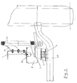
- Fig. 1 in schematischer Seitenansicht eine federnde Achsaufhängung einer gelenkten Achse eines Lastkraftwagens,
- Fig. 2 eine schematische Stirnansicht der gelenkten Achse nach Fig. 1,
- Fig. 3 eine Draufsicht auf die federnde Achsaufhängung nach den Fig. 1 und 2,
- Fig. 4 die Einzelheit des vorderen Federlagers in einer Seitenansicht ähnlich der Fig. 1, und
- Fig. 5 einen Querschnitt längs A-A der Fig. 4.
- 1 is a schematic side view of a resilient axle suspension of a steered axle of a truck,
- 2 shows a schematic end view of the steered axle according to FIG. 1,
- 3 is a plan view of the resilient axle suspension according to FIGS. 1 and 2,
- Fig. 4 shows the detail of the front spring bearing in a side view similar to FIG. 1, and
- 5 shows a cross section along AA of FIG. 4th
Gemäß Zeichnung ist eine federnde Achsaufhängung (30) eines Lastkraftwagens vorgesehen, wobei mit dem Fahrzeugrahmen (1) die Federlager (2 und 3) der Stahlfederung verschraubt sind.According to the drawing, a resilient axle suspension (30) of a truck is provided, the spring bearings (2 and 3) of the steel suspension being screwed to the vehicle frame (1).
Im vorderen Federlager (2) ist eine Führungsfeder (4) und ein Parabellenker (5) in noch zu beschreibender Weise angelenkt.A guide spring (4) and a parabolic link (5) are articulated in the front spring bearing (2) in a manner to be described.
Das hintere Federlager (3) ist mit einer Schwinge (6) ausgebildet und nimmt das "freie" Ende der im hinteren Abschnitt (9) verlängerten Führungsfeder (4) gelenkig auf.The rear spring bearing (3) is designed with a rocker (6) and articulates the "free" end of the guide spring (4) extended in the rear section (9).
Führungsfeder (4), Parabel- bzw. Federlenker (5) und unteres Stoßdämpferlager (7) sind mit der, die Fahrzeugräder tragenden, als Doppel-T-Profil ausgebildeten Fahrzeugachse (20) starr verspannt, und zwar durch vordere und hintere Schraubbolzen (25).The guide spring (4), parabolic or spring link (5) and lower shock absorber bearing (7) are rigidly clamped to the vehicle axle (20), which carries the vehicle wheels and is designed as a double-T profile, by means of front and rear screw bolts (25 ).
Der Federlenker (5) ist über die Achse (20) hinaus verlängert und bildet in seinem hinteren Abschnitt (18) das untere Lager einer Luftfeder (8), auf deren oberen Ende sich das Fahrgestell (1) abstützt, bzw. der zugeordnete Längsträger des Fahrzeugrahmens.The spring link (5) is extended beyond the axis (20) and forms in its rear section (18) the lower bearing of an air spring (8), on the upper end of which the chassis (1) is supported, or the associated longitudinal member of the Vehicle frame.
Das untere Stoßdämpferlager (7) und das obere Stoßdämpferlager (10) sind in diesem Fall aus Einbauraumgründen als Auslegerkonsolen ausgebildet.In this case, the lower shock absorber bearing (7) and the upper shock absorber bearing (10) are designed as bracket brackets for reasons of installation space.
Der Stoßdämpfer (21) kann auch direkt neben dem Fahrzeugrahmen (1) angeordnet sein. Da der Achsquerschnitt relativ torsionsweich ist, ist die Achsaufhängung (30) mit zusätzlichen Stabilisatoren versehen. Der vor der Achse (20) angeordnete, nach vorne offene Bügelstabilisator (11) stützt sich über Streben (12) und Stabilisatorlager (13) am Fahrzeugrahmen (1) ab.The shock absorber (21) can also be arranged directly next to the vehicle frame (1). Since the axle cross section is relatively torsionally soft, the axle suspension (30) is provided with additional stabilizers. The bow stabilizer (11), which is arranged in front of the axle (20) and is open to the front, is supported on the vehicle frame (1) via struts (12) and stabilizer bearings (13).
Die achsseitige Stabilisatorlagerung ist über die Achseinspannung (14) mit der Achse verbunden. Sollte der Bügelstabilisator (11) nicht ausreichen, die Aufbauneigung und damit die Achstorsion in Grenzen zu halten, besteht noch die Möglichkeit, die Enden der Federlenker (5) durch eine gemeinsame torsionssteife Brücke bzw. einen Torsionsstab miteinander zu verbinden.The axle-side stabilizer mounting is connected to the axle via the axle clamp (14). If the bow stabilizer (11) is not sufficient to keep the body inclination and thus the axle torsion within limits, there is still the option of connecting the ends of the spring links (5) to one another by means of a common torsionally rigid bridge or torsion bar.
Die Führungsfeder (4) ist eine Parabelfeder, deren angelenktes Ende als Federauge (14) ausgebildet ist, das ohne jedes oder ohne wesentliches Spiel eine zylindrische Hülse (15) umfaßt, die ebenfalls ohne Spiel den Lagerbolzen (16) umgibt, um den sich die Hülse mit dem vorderen Federauge (14) drehen kann. Die Führungsfeder (4) umfaßt den Bolzen (16) auf ihrer gesamten Breite. Anlaufscheiben, die zu beiden Seiten der Führungsfeder auf den Bolzen aufgesteckt sind, gleichen das seitliche Spiel aus und sorgen gleichzeitig für eine annähernd verzwängungsfreie Bewegungsmöglichkeit des Lenkerpakets sowie die Einleitung der Lenkerquerkräfte in den Federbock (aber erst, wenn das geringe seitliche Lenkerspiel (pro Seite ca. 1 mm) überwunden ist).The guide spring (4) is a parabolic spring, the articulated end of which is designed as a spring eye (14) which, without any or no substantial play, comprises a cylindrical sleeve (15) which also surrounds the bearing pin (16) without play, around which the Can rotate the sleeve with the front spring eye (14). The guide spring (4) comprises the bolt (16) over its entire width. Thrust washers, which are attached to the pin on both sides of the guide spring, compensate for the lateral play and at the same time ensure an almost free movement of the handlebar package as well as the introduction of the lateral shear forces into the spring bracket (but only when the small lateral handlebar play (approx . 1 mm) is overcome).
Der Federlenker (5) ist als Parabellenker ausgebildet. Das schwächste Ende (17) umfaßt das vordere Federauge (14) der Führungsfeder (4) so, daß der Parabel- oder Federlenker (5) bei gleichem oder wechselseitigem Einfedern der Achse (20) auf beiden Fahrzeugseiten keine Zugkräfte übertragen muß. Wenn sich die Achse (20) infolge ungleichmäßigen Einfederns beider Seiten aus seiner normalen Lage in Schräglage stellt, verbiegt und tordiert sich die Führungsfeder (4) und der Parabellenker (5), wobei sich die Mitte des schwächsten Endes (17) des Parabellenkers bzw. des vorderen Federauges des Parabellenkers (5) gegenüber der Mitte des vorderen Federauges (14) der Führungsfeder (4) verschiebt. Um diesen Verschiebeweg zu ermöglichen, ist das vordere Federauge (17) des Parabellenkers gemäß Fig. 4 ellipsenförmig oder oval gestaltet, so daß in Fahrzeuglängsrichtung vorne ein Spiel (a) und hinten ein Spiel (b) gegenüber dem vorderen Federauge (14) der Führungsfeder (4) verbleibt, wie dies in Fig. 4 veranschaulicht ist. In vertikaler Richtung ist das vordere Federauge (17) des Federlenkers (5) so ausgebildet, daß es mit leichter Vorspannung auf dem vorderen Federauge (14) der Führungsfeder (4) aufliegt. Beim Bremsen werden Führungsfeder (4) und Federlenker (5) dahingehend S-förmig verformt, daß sich der vor der Achse (20) liegende Teil des Federlenkers (5) zur Fahrbahn hin durchbiegt. Der Feder- oder Parabellenker (5) wird dabei weniger verformt als die Führungsfeder (4). Um unnötige Klappergeräusche zu vermeiden, werden Führungsfeder (4) und Federlenker (5) durch eine Federklammer (22) umschlossen, die ein vorgespanntes Gummipolster (23) gemäß Fig. 5 enthält und dadurch Führungsfeder und Federlenker gegeneinander gedrückt werden, gleichwohl eine Längsverschiebung zwischen den Teilen möglich ist.The spring link (5) is designed as a parabolic link. The weakest end (17) comprises the front spring eye (14) of the guide spring (4) so that the parabolic or spring link (5) does not have to transmit tensile forces on both sides of the vehicle with the same or reciprocal deflection of the axle (20). If the axle (20) is tilted from its normal position due to uneven deflection of both sides, the guide spring (4) and the parabolic link will bend and twist (5), the center of the weakest end (17) of the parabolic link or the front spring eye of the parabolic link (5) being displaced relative to the center of the front spring eye (14) of the guide spring (4). In order to enable this displacement path, the front spring eye (17) of the parabolic link according to FIG. 4 is designed elliptical or oval, so that in the longitudinal direction of the vehicle there is play (a) at the front and play (b) at the rear relative to the front spring eye (14) of the guide spring (4) remains as illustrated in FIG. 4. In the vertical direction, the front spring eye (17) of the spring link (5) is designed such that it rests with a slight prestress on the front spring eye (14) of the guide spring (4). When braking, the guide spring (4) and spring link (5) are deformed in an S-shape so that the part of the spring link (5) lying in front of the axle (20) bends towards the road. The spring or parabolic link (5) is deformed less than the guide spring (4). In order to avoid unnecessary rattling noises, the guide spring (4) and spring link (5) are enclosed by a spring clip (22) which contains a pre-tensioned rubber cushion (23) as shown in FIG Sharing is possible.
Die Führungs- oder Parabelfeder (4) und der Feder- bzw. Parabellenker (5) sind so ausgewalzt, daß die einander berührenden Seiten der Federn eben sind und die parabelförmige Auswalzung jeweils an der Außenseite liegt. Im Kontaktbereich kann es zu Reibkorrosion kommen. Daher ist die Federklammer (22) in einem Bereich in der Nähe der vorderen Federaugen (14 bzw. 17) befestigt, wo die Blattdicke aus Gründen der Krafteinleitung überdimensioniert ist.The guide or parabolic spring (4) and the spring or parabolic link (5) are rolled out so that the mutually contacting sides of the springs are flat and the parabolic roll is located on the outside. Fretting corrosion can occur in the contact area. The spring clip (22) is therefore fastened in an area in the vicinity of the front spring eyes (14 or 17) where the sheet thickness is oversized due to the introduction of force.
Das freie Ende der Führungsfeder (4) ist derart vorgesprengt, daß die Eigenfrequenz der Achsaufhängung (30) möglichst wenig von der Stahlfeder beeinflußt wird. Dabei muß allerdings gewährleistet sein, daß das leere Fahrzeug noch im gewünschten Maße abgesenkt werden kann und in diesem Zustand die Spannungen noch in zulässigen Grenzen liegen. Dadurch wird der Traganteil der Luftfeder (8) soweit wie möglich reduziert, und es kann eine im Durchmesser kleinere Luftfeder verwendet werden. Dies sollte allerdings nur im Fall begrenzten Einbauraums oder anderer schwerwiegender Gründe so ausgeführt sein. Prinzipiell ist eine möglichst große Luftfeder (8) anzustreben, um den Luftfedercharakter zu erhalten bzw. zu erhöhen.The free end of the guide spring (4) is pre-blasted so that the natural frequency of the axle suspension (30) is influenced as little as possible by the steel spring. However, it must be ensured that the empty vehicle can still be lowered to the desired extent and in this state the voltages are still within permissible limits. This reduces the load of the air spring (8) as much as possible, and an air spring with a smaller diameter can be used. However, this should only be done in the case of limited installation space or other serious reasons. In principle, the largest possible air spring (8) should be aimed at in order to maintain or increase the air spring character.
In statischer Lage sollte die Radachse nicht höher liegen als der Lagerbolzen (16) am vorderen Federlager (2), besser noch etwas unterhalb. Dadurch ergeben sich geringste Radstandsänderungen mit einem leicht untersteuernden Eigenlenkverhalten der Achse. Der Gummianschlagpuffer (24) kann, wie dies insbesondere der Fig. 2 zu entnehmen ist, über der Achse liegen, wobei das wirksame Volumen der Luftfeder (8) nicht eingeschränkt wird. Es ist auch denkbar, ihn in die Luftfeder (8) zu integrieren, wodurch sich bessere Notfedereigenschaften bei einem Ausfall der Luftfeder ergeben.In a static position, the wheel axle should not be higher than the bearing pin (16) on the front spring bearing (2), better still slightly below. This results in the smallest wheelbase changes with a slightly understeering self-steering behavior of the axle. The rubber stop buffer (24) can, as can be seen in particular in FIG. 2, lie above the axis, the effective volume of the air spring (8) not being restricted. It is also conceivable to integrate it into the air spring (8), which results in better emergency spring properties if the air spring fails.
Alle in der Beschreibung erwähnten und in der Zeichnung gezeigten Merkmale allein und/oder in sinnvoller Kombination sind erfindungswesentlich, auch soweit sie in den Ansprüchen nicht ausdrücklich beansprucht sind.All of the features mentioned in the description and shown in the drawing, alone and / or in a meaningful combination, are essential to the invention, even if they are not expressly claimed in the claims.
Claims (13)
- A spring axle suspension (30) for motor vehicles, especially commercial vehicles, having a guide spring (4) and a spring guide rod (5), both being pivoted to the common front spring bearing of the vehicle frame (1), in which a pneumatic spring (8) is mounted near the rear end of the spring guide rod (5) and is secured at the top the vehicle frame (1), characterised in that the guide spring (4), which is continuous, is in the form of a pre-cambered parabolic spring, the rear portion (9) of the parabolic spring behind the sprung axle (20) being longer that the front portion pivoted to the rolled end (14), and the spring guide rod (5), which is substantially unbent, is disposed above the parabolic spring and is prestressed together with the sprung (steering) axle (20) disposed underneath it.
- An axle suspension according to claim 1, characterised in that the pneumatic spring (8) is disposed above or a slight distance behind the sprung axle (20) and under the vehicle frame (1).
- An axle suspension according to claim 2, characterised in that the bottom end of a shock-absorber (21) is disposed above the sprung axle (20).
- An axle suspension according to claim 1, characterised in that when the pneumatic spring (8) is disposed above the sprung axle (20), the shock-absorber (21) is secured by a top and a bottom lateral bracket to the vehicle frame (1) and/or to the sprung axle (20) (Fig. 2).
- An axle suspension according to any one of claims 1 to 4, characterised in that the spring guide roc (5) is in the form of a leaf spring or parabolic spring.
- An axle suspension according to any one of claims 1 to 5, characterised in that the front end (17) of the spring guide rod (5) surrounds the front rolled end (14) of the guide spring (4) substantially without clearance in the vertical direction and with clearance in the horizontal direction (see Fig. 4).
- An axle suspension according to any one of claims 1 to 6, characterised in that the guide spring (4) is pivoted by a link (6) to the rear rolled end or spring bearing (3) of the vehicle frame (1), allowing the guide spring (4) to move horizontally during operation (Fig. 1).
- An axle suspension according to any one of claims 1 to 7, characterised in that the sprung axle (20) has at least one additional stabiliser and/or the axle suspension is reinforced by a transverse connection.
- An axle suspension according to claim 8, characterised in that the stabiliser is a curved stabiliser open at the front and secured to the axle (20) and braced by at least one strut (12) against a stabilising bearing (13) on the vehicle frame (1) (see Fig. 1).
- An axle suspension according to claim 8 or 9, characterised in that the stabiliser is a torsion rod which extends in the transverse direction of the vehicle and is secured between the sprung axles (20) on the two sides of the vehicle in the region of the two axles (20) or is secured to the rear ends (18) of the two spring guide rods (5).
- An axle suspension according to any one of claims 1 to 10, characterised in that the guide spring (4) and the spring guide rod (5), in the region of the front rolled end (14), are secured by a spring clamp (22) which enables the guide spring (4) to move longitudinally relative to the spring guide rod (5) during operation.
- An axle suspension according to claim 11, characterised in that the spring clamp (22) comprises an internal prestressed rubber pad (23) which presses the guide spring (4) and the spring guide rod (5) against one another (see Fig. 5).
- An axle suspension according to claim 11 or 12, characterised in that the guide spring (4) and the spring guide rod (5) are spaced apart from one another in the longitudinal region between the spring clamp (22) and the sprung axle (20) (see Figs. 1 and 4).
Applications Claiming Priority (2)
| Application Number | Priority Date | Filing Date | Title |
|---|---|---|---|
| DE3825105 | 1988-07-23 | ||
| DE3825105A DE3825105A1 (en) | 1988-07-23 | 1988-07-23 | SPRING AXLE SUSPENSION FOR MOTOR VEHICLES, IN PARTICULAR COMMERCIAL VEHICLES |
Publications (2)
| Publication Number | Publication Date |
|---|---|
| EP0352541A1 EP0352541A1 (en) | 1990-01-31 |
| EP0352541B1 true EP0352541B1 (en) | 1993-03-10 |
Family
ID=6359417
Family Applications (1)
| Application Number | Title | Priority Date | Filing Date |
|---|---|---|---|
| EP89112650A Expired - Lifetime EP0352541B1 (en) | 1988-07-23 | 1989-07-11 | Resilient axle suspension for motor vehicles, in particular for utility vehicles |
Country Status (2)
| Country | Link |
|---|---|
| EP (1) | EP0352541B1 (en) |
| DE (2) | DE3825105A1 (en) |
Cited By (1)
| Publication number | Priority date | Publication date | Assignee | Title |
|---|---|---|---|---|
| US7744105B2 (en) | 2008-04-15 | 2010-06-29 | Hendrickson Usa, L.L.C. | Isolated spring clamp group |
Families Citing this family (14)
| Publication number | Priority date | Publication date | Assignee | Title |
|---|---|---|---|---|
| DE4107306C1 (en) * | 1991-03-07 | 1992-04-30 | Man Nutzfahrzeuge Ag, 8000 Muenchen, De | |
| DE4212313A1 (en) * | 1992-04-13 | 1993-10-14 | Iveco Magirus | Spring axle suspension for motor vehicles with spring, stabilizer and shock absorber |
| AT401496B (en) * | 1992-08-20 | 1996-09-25 | Steyr Nutzfahrzeuge | FASTENING A RIGID FRONT AXLE, ESPECIALLY A COMMERCIAL VEHICLE |
| GB9603216D0 (en) * | 1996-02-15 | 1996-04-17 | Amk Automotive Limited | Improvements in vehicle suspensions |
| NL1003649C2 (en) * | 1996-07-19 | 1998-01-21 | Weweler Nv | Spring hand for a vehicle suspension system. |
| US5938221A (en) * | 1997-12-08 | 1999-08-17 | The Boler Company | Tapered convolute leaf spring for truck suspensions |
| NZ535767A (en) * | 2000-05-17 | 2006-06-30 | Hendrickson Int Corp | Truck suspensions incorporating asymmetric leaf springs |
| NL1018772C1 (en) * | 2001-08-16 | 2003-02-18 | Weweler Nv | Attaching a support bracket of an axle assembly to a vehicle chassis. |
| ITTO20020268A1 (en) * | 2002-03-26 | 2003-09-26 | Iveco Fiat | INDEPENDENT SUSPENSION FOR A WHEEL OF AN INDUSTRIAL VEHICLE. |
| DE102005014231A1 (en) * | 2005-03-30 | 2006-10-05 | Daimlerchrysler Ag | motor vehicle |
| DE102006052218B4 (en) * | 2006-11-06 | 2014-03-27 | Saf-Holland Gmbh | Holding device for an axle |
| EP2319716B1 (en) * | 2009-11-06 | 2012-06-27 | Iveco S.p.A. | Front suspension system for an industrial vehicle with full air braking system |
| ES2425021B2 (en) * | 2011-11-30 | 2014-04-15 | Accesorios Y Elevadores Valencia, S.L. | Quick connect lifting device |
| ITUA20164285A1 (en) * | 2016-06-10 | 2017-12-10 | Iveco Defence Vehicles S P A | FRONT SUSPENSION SYSTEM |
Family Cites Families (8)
| Publication number | Priority date | Publication date | Assignee | Title |
|---|---|---|---|---|
| DE1755017A1 (en) * | 1968-03-21 | 1971-11-18 | Kaessbohrer Fahrzeug Karl | Axle suspension for trucks or buses with rigid axles |
| DE2100048C2 (en) * | 1971-01-02 | 1981-12-17 | Friedrich 6142 Bensheim Schaeff | Suspension for vehicle wheel axles |
| US3841655A (en) * | 1971-12-30 | 1974-10-15 | Sauer Achsenfab | Spring suspension for motor vehicle axles |
| GB1406651A (en) * | 1972-10-03 | 1975-09-17 | Woodhead Ltd Jonas | Leaf springs |
| US3850445A (en) * | 1974-02-11 | 1974-11-26 | Lear Siegler Inc | Combined air spring and leaf spring suspension |
| EP0025299B1 (en) * | 1979-08-21 | 1984-01-04 | John Marmaduke Dickson-Simpson | Axle suspension |
| FR2529838B1 (en) * | 1982-07-12 | 1987-02-27 | Renault Vehicules Ind | PNEUMATIC SUSPENSION DEVICE FOR INDUSTRIAL VEHICLE |
| DE8716234U1 (en) * | 1987-05-16 | 1988-01-28 | Bergische Achsenfabrik Fr. Kotz & Soehne, 5276 Wiehl, De |
-
1988
- 1988-07-23 DE DE3825105A patent/DE3825105A1/en not_active Withdrawn
-
1989
- 1989-07-11 EP EP89112650A patent/EP0352541B1/en not_active Expired - Lifetime
- 1989-07-11 DE DE8989112650T patent/DE58903701D1/en not_active Expired - Lifetime
Cited By (2)
| Publication number | Priority date | Publication date | Assignee | Title |
|---|---|---|---|---|
| US7744105B2 (en) | 2008-04-15 | 2010-06-29 | Hendrickson Usa, L.L.C. | Isolated spring clamp group |
| US7931287B2 (en) | 2008-04-15 | 2011-04-26 | Hendrickson Usa, L.L.C. | Isolated spring clamp group |
Also Published As
| Publication number | Publication date |
|---|---|
| DE58903701D1 (en) | 1993-04-15 |
| EP0352541A1 (en) | 1990-01-31 |
| DE3825105A1 (en) | 1990-02-08 |
Similar Documents
| Publication | Publication Date | Title |
|---|---|---|
| EP0776275B1 (en) | Axle suspension for rigid vehicle axles | |
| DE4340557C2 (en) | Suspension | |
| DE4092219C2 (en) | Independent suspension system | |
| EP0352541B1 (en) | Resilient axle suspension for motor vehicles, in particular for utility vehicles | |
| DE1780251A1 (en) | Vehicle suspension | |
| DE102013210338A1 (en) | Multi-link rear axle for a vehicle | |
| DE60008009T2 (en) | SINGLE SUSPENSION | |
| EP1302342B1 (en) | Suspension system for a pendular axle | |
| DE4338651A1 (en) | Suspension for a rigid axle of a vehicle, especially a truck or bus | |
| EP1231129B1 (en) | Truck | |
| EP2435263B1 (en) | Independent vehicle suspension | |
| EP1541393B1 (en) | Torsion axle | |
| WO2004069567A1 (en) | Wheel suspension for motor vehicles | |
| EP1419909A2 (en) | Four link rear axle suspension for a vehicle | |
| DE3329686C2 (en) | Track constant axle suspension, especially rear axle suspension, for motor vehicles | |
| DE10055859A1 (en) | Non-driven axle system comprises axle guides mounted on pivots on either side of vehicle, axle being held in clamps attached to guides | |
| DE4427172C2 (en) | Axle guidance for vehicles, in particular rear axle guidance for commercial vehicles | |
| EP0464415B1 (en) | Suspension with longitudinal arms for motorvehicles and trailers | |
| DE3133312A1 (en) | Body-side bearing support of a motor vehicle | |
| DE2439365A1 (en) | Suspension with upper and lower transverse arms - has upper arms pivoted on either chassis side and shorter lower links | |
| EP0881107B1 (en) | Vehicle, in particular utility vehicle | |
| DE1680663A1 (en) | Wheel suspension for rigid axles of motor vehicles | |
| DE19542105A1 (en) | Dead beam axle for vehicle | |
| DE3302627A1 (en) | Independent wheel suspension for the wheels of a motor vehicle rear axle | |
| EP0903251A1 (en) | Wheel axle for a motor vehicle |
Legal Events
| Date | Code | Title | Description |
|---|---|---|---|
| PUAI | Public reference made under article 153(3) epc to a published international application that has entered the european phase |
Free format text: ORIGINAL CODE: 0009012 |
|
| AK | Designated contracting states |
Kind code of ref document: A1 Designated state(s): DE FR GB IT NL SE |
|
| 17P | Request for examination filed |
Effective date: 19900711 |
|
| 17Q | First examination report despatched |
Effective date: 19911028 |
|
| GRAA | (expected) grant |
Free format text: ORIGINAL CODE: 0009210 |
|
| AK | Designated contracting states |
Kind code of ref document: B1 Designated state(s): DE FR GB IT NL SE |
|
| ITF | It: translation for a ep patent filed |
Owner name: JACOBACCI CASETTA & PERANI S.P.A. |
|
| ET | Fr: translation filed | ||
| REF | Corresponds to: |
Ref document number: 58903701 Country of ref document: DE Date of ref document: 19930415 |
|
| GBT | Gb: translation of ep patent filed (gb section 77(6)(a)/1977) |
Effective date: 19930615 |
|
| PLBE | No opposition filed within time limit |
Free format text: ORIGINAL CODE: 0009261 |
|
| STAA | Information on the status of an ep patent application or granted ep patent |
Free format text: STATUS: NO OPPOSITION FILED WITHIN TIME LIMIT |
|
| 26N | No opposition filed | ||
| EAL | Se: european patent in force in sweden |
Ref document number: 89112650.0 |
|
| REG | Reference to a national code |
Ref country code: GB Ref legal event code: IF02 |
|
| PG25 | Lapsed in a contracting state [announced via postgrant information from national office to epo] |
Ref country code: IT Free format text: LAPSE BECAUSE OF NON-PAYMENT OF DUE FEES Effective date: 20050711 |
|
| PGFP | Annual fee paid to national office [announced via postgrant information from national office to epo] |
Ref country code: DE Payment date: 20080916 Year of fee payment: 20 Ref country code: SE Payment date: 20080625 Year of fee payment: 20 |
|
| PGFP | Annual fee paid to national office [announced via postgrant information from national office to epo] |
Ref country code: NL Payment date: 20080630 Year of fee payment: 20 |
|
| PGFP | Annual fee paid to national office [announced via postgrant information from national office to epo] |
Ref country code: GB Payment date: 20080630 Year of fee payment: 20 |
|
| REG | Reference to a national code |
Ref country code: GB Ref legal event code: PE20 Expiry date: 20090710 |
|
| NLV7 | Nl: ceased due to reaching the maximum lifetime of a patent |
Effective date: 20090711 |
|
| EUG | Se: european patent has lapsed | ||
| PG25 | Lapsed in a contracting state [announced via postgrant information from national office to epo] |
Ref country code: GB Free format text: LAPSE BECAUSE OF EXPIRATION OF PROTECTION Effective date: 20090710 Ref country code: NL Free format text: LAPSE BECAUSE OF EXPIRATION OF PROTECTION Effective date: 20090711 |
|
| PGFP | Annual fee paid to national office [announced via postgrant information from national office to epo] |
Ref country code: FR Payment date: 20080422 Year of fee payment: 20 |
|
| PGFP | Annual fee paid to national office [announced via postgrant information from national office to epo] |
Ref country code: IT Payment date: 20080618 Year of fee payment: 20 |
|
| PGRI | Patent reinstated in contracting state [announced from national office to epo] |
Ref country code: IT Effective date: 20110616 |