EP0352148B1 - Dispositif et méthode pour effectuer des mesures ou des interventions dans un puits - Google Patents
Dispositif et méthode pour effectuer des mesures ou des interventions dans un puits Download PDFInfo
- Publication number
- EP0352148B1 EP0352148B1 EP89401353A EP89401353A EP0352148B1 EP 0352148 B1 EP0352148 B1 EP 0352148B1 EP 89401353 A EP89401353 A EP 89401353A EP 89401353 A EP89401353 A EP 89401353A EP 0352148 B1 EP0352148 B1 EP 0352148B1
- Authority
- EP
- European Patent Office
- Prior art keywords
- rod
- well
- instrument
- reel
- embedded
- Prior art date
- Legal status (The legal status is an assumption and is not a legal conclusion. Google has not performed a legal analysis and makes no representation as to the accuracy of the status listed.)
- Expired - Lifetime
Links
- 238000000034 method Methods 0.000 title claims description 7
- 238000005259 measurement Methods 0.000 title description 13
- 239000000463 material Substances 0.000 claims description 11
- 239000002131 composite material Substances 0.000 claims description 10
- 239000000835 fiber Substances 0.000 claims description 8
- 238000001125 extrusion Methods 0.000 claims description 4
- 239000012530 fluid Substances 0.000 claims description 4
- 239000011159 matrix material Substances 0.000 claims description 4
- 230000007935 neutral effect Effects 0.000 claims description 4
- 230000003287 optical effect Effects 0.000 claims description 4
- 229920001169 thermoplastic Polymers 0.000 claims description 4
- OKTJSMMVPCPJKN-UHFFFAOYSA-N Carbon Chemical compound [C] OKTJSMMVPCPJKN-UHFFFAOYSA-N 0.000 claims description 3
- 239000004952 Polyamide Substances 0.000 claims description 3
- 238000005299 abrasion Methods 0.000 claims description 3
- 229910052799 carbon Inorganic materials 0.000 claims description 3
- 239000003795 chemical substances by application Substances 0.000 claims description 3
- 239000011521 glass Substances 0.000 claims description 3
- 229920002647 polyamide Polymers 0.000 claims description 3
- 230000003014 reinforcing effect Effects 0.000 claims description 3
- 229920005989 resin Polymers 0.000 claims description 3
- 239000011347 resin Substances 0.000 claims description 3
- 229920001187 thermosetting polymer Polymers 0.000 claims description 3
- 239000004416 thermosoftening plastic Substances 0.000 claims description 3
- 239000003822 epoxy resin Substances 0.000 claims description 2
- 239000003365 glass fiber Substances 0.000 claims description 2
- 239000003208 petroleum Substances 0.000 claims description 2
- 229920000647 polyepoxide Polymers 0.000 claims description 2
- 229920000642 polymer Polymers 0.000 claims description 2
- 239000004706 High-density cross-linked polyethylene Substances 0.000 claims 1
- 229920003235 aromatic polyamide Polymers 0.000 claims 1
- 230000005489 elastic deformation Effects 0.000 claims 1
- 125000002573 ethenylidene group Chemical group [*]=C=C([H])[H] 0.000 claims 1
- 230000001747 exhibiting effect Effects 0.000 claims 1
- 229920004932 high density cross-linked polyethylene Polymers 0.000 claims 1
- 239000007787 solid Substances 0.000 claims 1
- 239000004020 conductor Substances 0.000 description 5
- 238000004519 manufacturing process Methods 0.000 description 5
- 238000004873 anchoring Methods 0.000 description 4
- 238000005452 bending Methods 0.000 description 3
- 230000015572 biosynthetic process Effects 0.000 description 3
- 230000006835 compression Effects 0.000 description 3
- 238000007906 compression Methods 0.000 description 3
- 238000005553 drilling Methods 0.000 description 3
- 238000005755 formation reaction Methods 0.000 description 3
- 240000007817 Olea europaea Species 0.000 description 2
- 239000002033 PVDF binder Substances 0.000 description 2
- 238000005260 corrosion Methods 0.000 description 2
- 230000007797 corrosion Effects 0.000 description 2
- 229920001903 high density polyethylene Polymers 0.000 description 2
- 239000004700 high-density polyethylene Substances 0.000 description 2
- 239000002184 metal Substances 0.000 description 2
- 238000012544 monitoring process Methods 0.000 description 2
- 239000004033 plastic Substances 0.000 description 2
- 229920003023 plastic Polymers 0.000 description 2
- 229920002981 polyvinylidene fluoride Polymers 0.000 description 2
- 238000007789 sealing Methods 0.000 description 2
- 238000004804 winding Methods 0.000 description 2
- 229920000271 Kevlar® Polymers 0.000 description 1
- 229910000831 Steel Inorganic materials 0.000 description 1
- 239000004519 grease Substances 0.000 description 1
- 239000011796 hollow space material Substances 0.000 description 1
- 238000009434 installation Methods 0.000 description 1
- 239000004761 kevlar Substances 0.000 description 1
- 229920001296 polysiloxane Polymers 0.000 description 1
- 239000012783 reinforcing fiber Substances 0.000 description 1
- 239000005060 rubber Substances 0.000 description 1
- 239000002689 soil Substances 0.000 description 1
- 239000010959 steel Substances 0.000 description 1
- 239000000126 substance Substances 0.000 description 1
- 229920002994 synthetic fiber Polymers 0.000 description 1
Images
Classifications
-
- G—PHYSICS
- G01—MEASURING; TESTING
- G01V—GEOPHYSICS; GRAVITATIONAL MEASUREMENTS; DETECTING MASSES OR OBJECTS; TAGS
- G01V11/00—Prospecting or detecting by methods combining techniques covered by two or more of main groups G01V1/00 - G01V9/00
- G01V11/002—Details, e.g. power supply systems for logging instruments, transmitting or recording data, specially adapted for well logging, also if the prospecting method is irrelevant
- G01V11/005—Devices for positioning logging sondes with respect to the borehole wall
-
- E—FIXED CONSTRUCTIONS
- E21—EARTH OR ROCK DRILLING; MINING
- E21B—EARTH OR ROCK DRILLING; OBTAINING OIL, GAS, WATER, SOLUBLE OR MELTABLE MATERIALS OR A SLURRY OF MINERALS FROM WELLS
- E21B17/00—Drilling rods or pipes; Flexible drill strings; Kellies; Drill collars; Sucker rods; Cables; Casings; Tubings
- E21B17/003—Drilling rods or pipes; Flexible drill strings; Kellies; Drill collars; Sucker rods; Cables; Casings; Tubings with electrically conducting or insulating means
-
- E—FIXED CONSTRUCTIONS
- E21—EARTH OR ROCK DRILLING; MINING
- E21B—EARTH OR ROCK DRILLING; OBTAINING OIL, GAS, WATER, SOLUBLE OR MELTABLE MATERIALS OR A SLURRY OF MINERALS FROM WELLS
- E21B17/00—Drilling rods or pipes; Flexible drill strings; Kellies; Drill collars; Sucker rods; Cables; Casings; Tubings
- E21B17/20—Flexible or articulated drilling pipes, e.g. flexible or articulated rods, pipes or cables
- E21B17/206—Flexible or articulated drilling pipes, e.g. flexible or articulated rods, pipes or cables with conductors, e.g. electrical, optical
-
- E—FIXED CONSTRUCTIONS
- E21—EARTH OR ROCK DRILLING; MINING
- E21B—EARTH OR ROCK DRILLING; OBTAINING OIL, GAS, WATER, SOLUBLE OR MELTABLE MATERIALS OR A SLURRY OF MINERALS FROM WELLS
- E21B47/00—Survey of boreholes or wells
-
- G—PHYSICS
- G02—OPTICS
- G02B—OPTICAL ELEMENTS, SYSTEMS OR APPARATUS
- G02B6/00—Light guides; Structural details of arrangements comprising light guides and other optical elements, e.g. couplings
- G02B6/44—Mechanical structures for providing tensile strength and external protection for fibres, e.g. optical transmission cables
- G02B6/4401—Optical cables
- G02B6/4415—Cables for special applications
- G02B6/4427—Pressure resistant cables, e.g. undersea cables
-
- G—PHYSICS
- G02—OPTICS
- G02B—OPTICAL ELEMENTS, SYSTEMS OR APPARATUS
- G02B6/00—Light guides; Structural details of arrangements comprising light guides and other optical elements, e.g. couplings
- G02B6/46—Processes or apparatus adapted for installing or repairing optical fibres or optical cables
- G02B6/50—Underground or underwater installation; Installation through tubing, conduits or ducts
Definitions
- the present invention relates to a device, an application of this device and a method using this device, making it possible to carry out measurements or / and interventions in a well at the level of surrounding formations.
- the invention is particularly applicable when it is a question of carrying out measurements and / or interventions at the level of geological formations crossed by a well.
- the measurements carried out may include the recording of the pressure and the bottom temperature of the well, the measurement (focused or not) of the electrical resistivity of the formations, as well as acoustic, nuclear, etc. measurements.
- the present invention is particularly well suited for carrying out measurements or interventions in a petroleum effluent production well.
- This well may preferably include tubes or drains which delimit the walls thereof.
- Patent EP-A-0 / 256,601 describes for example a method and a device for drilling in the ground using an assembly comprising two concentric tubes of metal or of synthetic material, rigid and unwound from a reel by plastic deformation of the tube material.
- the tubes described in these two documents which are made of metal, have little flexibility to facilitate the movement of the instrument. This flexibility produces plastic deformations during its winding on the drum, or during its unwinding of the drum.
- the electrical conductor which they can contain is arranged in the hollow space of the tube. The installation of such a conductor poses a problem, because it cannot be carried out while the tube is wound. This tube is also relatively heavy.
- Patent FR-B-1,249,236 describes a flexible steel tube usable for drilling the ground. This tube is very expensive to manufacture.
- the rod is in particular elastic in bending and rigid in compression, this rod comprising at least one line suitable for the transfer of energy or information, such as an electrical, fluidic, or optical line, the line being embedded in the rod, and the rod is adapted to be wound on at least one reel and comprises a composite material or a non-composite polymeric material.
- the composite material may consist, for example, of glass, carbon or polyaramide fibers, such as Kevlar which is a trademark registered by Dupont de Nemours, these fibers being embedded in a matrix of thermoplastic or thermosetting resin.
- the polymeric material devoid of reinforcing elements may be chosen from elements from the group of the following polymers: polyamide, polyvinylidene fluoride, crosslinked high density polyethylene.
- the rod may be substantially full.
- the transfer line may be substantially disposed in the vicinity of the neutral fiber.
- the rod can be adapted to resist twisting.
- the nature of the material constituting the external part of the rod may be adapted to reduce the friction between the rod and the wall of the well.
- the rod may be manufactured by a machine producing continuously, in particular by extrusion or by pultrusion.
- the rod may include several lines of energy or information transfer.
- the rod may be hollow and the line may be embedded in the thickness of said rod.
- the outer part of the rod may include an anti-abrasion agent.
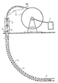
- the reference 1 indicates the reel on which is wound a rod 2 which is used for the movements of the instrument 3 in the well 4, so as to carry out the measurements or the interventions in one or more zones of the well 4.
- the rod 2 which is very flexible, leaves the reel 1 by passing over a deflection member 5, such as a set of pulleys, adapted to position the rod in the axis of the well whatever the position of the reel and its filling, and passes through means 6 of traction and thrust adapted to push the rod 2 into the well, to retain it or to extract it therefrom.
- a deflection member 5 such as a set of pulleys
- These traction and pushing means 6 can, for example, consist of two rubber tracks enclosing the rod 2 and moving in the desired direction to maneuver the rod 2.
- the rod 2 which is resistant to compression so as to allow a thrust on the instrument 3, is made of a very limited number of elements and may even have only one.
- the rod 2 comprises at least one line suitable for transferring energy or information, such as one (or more) electrical, fluidic or optical line, which makes it possible to connect the instrument 3 placed in the well at the lower end of the rod to the surface where the upper end of the rod is located 2. To this upper end are connected, optionally by means of a rotating connector, apparatus 7 for monitoring or controlling the instrument 3.
- a such rod can be made of composite material with glass, carbon, polyaramide reinforcing fibers embedded in a matrix of thermoplastic or thermosetting resin. This composite material may advantageously consist of glass fibers embedded in an epoxy resin.
- the nature of the matrix and of the fibers can be judiciously chosen to reduce friction and wear due to friction between the rod 2 and the wall of the well 4 during movements of the instrument 3.
- the line adapted to the transfer of energy and information is advantageously embedded in the rod 2 at the time of its manufacture.
- the rod 2 can also be made of a polymeric material resistant in particular to the mechanical stresses of use, and to the thermal and chemical stresses encountered in the well. It has been found that thermoplastic polymers of the polyamide, polyvinylidene fluoride or crosslinked high density polyethylene type make it possible to produce a flexible flexible rod which is resistant to corrosion according to the invention.
- Extrusion and pultrusion are called each of the processes by which a malleable material is respectively pushed by a press into a die or pulled at the outlet of a die.
- the rod 2 may be full (or massive). It can also be hollow and the transfer line can be embedded in this rod.
- the rod 2 may include means enabling it to resist torsional forces, such as a reinforcing braid disposed in the vicinity of the periphery of the rod.
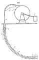
- the upper part of the well 4 comprises means 21 for closing the well 4 and sealing with the rod 2 which make it possible to hold the instrument 3 in the well or to move the instrument 3 while it is connected to the soil surface by the rod 2.
- a conduit 22 then allowing the evacuation of the effluents produced.
- the rod 2 (Fig. 2) is only disposed between the instrument 3 and a drill rod 8 adapted to compress the rod 2, so as to advance the instrument 3 into the well 4.
- the drill rod is connected to the ground surface by a flexible element 9 which can be a rod such as that connecting the drill rod 8 to the instrument 3, or else a cable provided with conductors, optical lines or fluidics.
- the flexible element 9 like the rod 2 are wound on the reel 1 and unwound from the reel via the return member 5, the mass-rod 8 being removed from the rod 2 and from the flexible element 9 for allow winding.
- the length of the rod 2 will be such that the distance D over which the mass-rod 9 can move is at least equal to the length L of the area to be explored.
- the operation of the instrument 3, or the information coming from it, is conveyed through the rod 2, the flexible element 9 and possibly the mass-rod 8, by the transfer lines or the conductors of those -this to the surface where the instruments 7 for monitoring and controlling the instrument 3 are located.
- the rod 2 is produced in a single section, for example 1000, 2000, 3000 meters, but it will not depart from the scope of the invention by using for this rod 2 a limited number of sections assembled together. following the others.
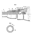
- Figure 3 shows in detail the mechanical connection between the lower end of the rod 2 and the instrument 3.
- the mechanical connection between the rod 2 and the instrument 3 which have respectively (for example) diameters of 25 millimeters and 75 millimeters, is in particular ensured by the anchoring of an olive 10 in the rod 2, the anchoring being carried out by a cooperation of the nuts 11 and 12 having conical bores which press the olive 10 onto the stem, this anchoring assembly 10, 11, 12 being fixed to the body of the instrument 3 by a collar nut 13 cooperating with a collar 14 integral with the anchoring assembly, in particular of the nut 12.
- the electrical connection of the transfer line 15 with the instrument 3 is carried out by a female plug 16 cooperating with a sealed electrical crossing of the instrument.
- a female plug and a bushing that can be used for this connection are for example available from the company DEUTSCH under the reference type 9701.
- the space 17 between the end of the rod 2 and the instrument 3 is filled with an insulating fluid, such as silicone grease, and is confined by means of sealing means, such as O-rings 18.
- an insulating fluid such as silicone grease
- the rod 2 is hollow and comprises one or more electrical conductors, or more generally at least one transfer line embedded in the thickness of the rod.
- This particular arrangement makes it possible in particular to increase the inertia in bending of the rod by optimizing the material used, to use the empty central part to dispose a fluid, and possibly to circulate a working fluid, such as mud from drilling.
- the transfer lines 19, 20 can be arranged symmetrically or asymmetrically in the rod 2.
Landscapes
- Physics & Mathematics (AREA)
- Engineering & Computer Science (AREA)
- Life Sciences & Earth Sciences (AREA)
- Geology (AREA)
- Mining & Mineral Resources (AREA)
- General Life Sciences & Earth Sciences (AREA)
- General Physics & Mathematics (AREA)
- Geochemistry & Mineralogy (AREA)
- Environmental & Geological Engineering (AREA)
- Fluid Mechanics (AREA)
- Optics & Photonics (AREA)
- Mechanical Engineering (AREA)
- Geophysics (AREA)
- Earth Drilling (AREA)
- Spectrometry And Color Measurement (AREA)
- Automatic Analysis And Handling Materials Therefor (AREA)
- Image Analysis (AREA)
- A Measuring Device Byusing Mechanical Method (AREA)
- Investigating Strength Of Materials By Application Of Mechanical Stress (AREA)
- Rigid Pipes And Flexible Pipes (AREA)
Applications Claiming Priority (2)
| Application Number | Priority Date | Filing Date | Title |
|---|---|---|---|
| FR8806828 | 1988-05-20 | ||
| FR8806828A FR2631708B1 (fr) | 1988-05-20 | 1988-05-20 | Dispositif permettant d'effectuer des mesures ou des interventions dans un puits, methode utilisant le dispositif et applications du dispositif |
Publications (2)
| Publication Number | Publication Date |
|---|---|
| EP0352148A1 EP0352148A1 (fr) | 1990-01-24 |
| EP0352148B1 true EP0352148B1 (fr) | 1992-07-15 |
Family
ID=9366509
Family Applications (1)
| Application Number | Title | Priority Date | Filing Date |
|---|---|---|---|
| EP89401353A Expired - Lifetime EP0352148B1 (fr) | 1988-05-20 | 1989-05-16 | Dispositif et méthode pour effectuer des mesures ou des interventions dans un puits |
Country Status (7)
| Country | Link |
|---|---|
| US (1) | US5184682A (no) |
| EP (1) | EP0352148B1 (no) |
| BR (1) | BR8902356A (no) |
| CA (1) | CA1336261C (no) |
| DE (1) | DE68902106T2 (no) |
| FR (1) | FR2631708B1 (no) |
| NO (1) | NO174978C (no) |
Cited By (15)
| Publication number | Priority date | Publication date | Assignee | Title |
|---|---|---|---|---|
| WO1991019884A1 (en) * | 1990-06-15 | 1991-12-26 | Westech Geophysical, Inc. | Video logging system having remote power source |
| US5202944A (en) * | 1990-06-15 | 1993-04-13 | Westech Geophysical, Inc. | Communication and power cable |
| GB2261451A (en) * | 1991-11-13 | 1993-05-19 | Inst Francais Du Petrole | Logging and/or servicing wells |
| FR2769665A1 (fr) | 1997-10-13 | 1999-04-16 | Inst Francais Du Petrole | Methode et systeme de mesure dans un conduit horizontal |
| FR2769664A1 (fr) | 1997-10-13 | 1999-04-16 | Inst Francais Du Petrole | Methode et systeme de mesure comportant une extension semi-rigide |
| US5921285A (en) * | 1995-09-28 | 1999-07-13 | Fiberspar Spoolable Products, Inc. | Composite spoolable tube |
| US6016845A (en) * | 1995-09-28 | 2000-01-25 | Fiber Spar And Tube Corporation | Composite spoolable tube |
| US6157761A (en) * | 1997-10-13 | 2000-12-05 | Institut Francais Du Petrole | Reinforced composite rod |
| US6663453B2 (en) | 2001-04-27 | 2003-12-16 | Fiberspar Corporation | Buoyancy control systems for tubes |
| US6706348B2 (en) | 1997-10-10 | 2004-03-16 | Fiberspar Corporation | Composite spoolable tube with sensor |
| US8678041B2 (en) | 2004-02-27 | 2014-03-25 | Fiberspar Corporation | Fiber reinforced spoolable pipe |
| US8955599B2 (en) | 2009-12-15 | 2015-02-17 | Fiberspar Corporation | System and methods for removing fluids from a subterranean well |
| US8985154B2 (en) | 2007-10-23 | 2015-03-24 | Fiberspar Corporation | Heated pipe and methods of transporting viscous fluid |
| US9127546B2 (en) | 2009-01-23 | 2015-09-08 | Fiberspar Coproation | Downhole fluid separation |
| US9206676B2 (en) | 2009-12-15 | 2015-12-08 | Fiberspar Corporation | System and methods for removing fluids from a subterranean well |
Families Citing this family (40)
| Publication number | Priority date | Publication date | Assignee | Title |
|---|---|---|---|---|
| FR2658558B1 (fr) * | 1990-02-22 | 1992-06-12 | Ungemach Pierre | Dispositif de protection des puits face aux risques de corrosion ou depots dus a la nature du fluid produit ou en place dans le puits. |
| FR2691203A1 (fr) * | 1992-05-15 | 1993-11-19 | Mr Ind | Tube auxiliaire sans raccord pour puits de forage profond. |
| FR2708055B1 (fr) * | 1993-07-19 | 1995-08-25 | Inst Francais Du Petrole | Dispositif de liaison pour tige composite. |
| GB2283035B (en) * | 1993-10-25 | 1997-08-06 | Camco Int | Coiled tubing with signal transmitting passageway |
| FR2711728B1 (fr) * | 1993-10-25 | 1998-03-27 | Camco Int | Tubage bobiné muni d'un passage de transmission de signal. |
| FR2712628B1 (fr) * | 1993-11-15 | 1996-01-12 | Inst Francais Du Petrole | Dispositif et méthode de mesure dans un puits de production d'hydrocarbures . |
| FR2712627B1 (fr) * | 1993-11-17 | 1996-01-05 | Schlumberger Services Petrol | Procédé et dispositif pour surveiller et/ou étudier un réservoir d'hydrocarbures traversé par un puits. |
| US5988702A (en) * | 1995-09-28 | 1999-11-23 | Fiber Spar And Tube Corporation | Composite coiled tubing end connector |
| US7498509B2 (en) * | 1995-09-28 | 2009-03-03 | Fiberspar Corporation | Composite coiled tubing end connector |
| US8678042B2 (en) | 1995-09-28 | 2014-03-25 | Fiberspar Corporation | Composite spoolable tube |
| FR2745847B1 (fr) * | 1996-03-08 | 2000-09-15 | Inst Francais Du Petrole | Systeme de transmission de mesure comportant un convertisseur optoelectrique |
| AU2759699A (en) * | 1998-02-17 | 1999-08-30 | Vibration Technology Llc | Downhole coiled tubing recovery apparatus |
| US6264244B1 (en) | 1998-04-29 | 2001-07-24 | Halliburton Energy Services, Inc. | End connector for composite coiled tubing |
| US7407006B2 (en) * | 1999-01-04 | 2008-08-05 | Weatherford/Lamb, Inc. | System for logging formations surrounding a wellbore |
| US7513305B2 (en) * | 1999-01-04 | 2009-04-07 | Weatherford/Lamb, Inc. | Apparatus and methods for operating a tool in a wellbore |
| US7185700B2 (en) * | 2004-06-14 | 2007-03-06 | Weatherford/Lamb, Inc. | Separable plug for use with a wellbore tool |
| US6148925A (en) * | 1999-02-12 | 2000-11-21 | Moore; Boyd B. | Method of making a conductive downhole wire line system |
| US6321596B1 (en) | 1999-04-21 | 2001-11-27 | Ctes L.C. | System and method for measuring and controlling rotation of coiled tubing |
| EP1224417B1 (en) | 1999-10-01 | 2005-08-10 | Fiberspar Corporation | Composite coiled tubing end connector and pipe-to-pipe connector |
| US6464014B1 (en) | 2000-05-23 | 2002-10-15 | Henry A. Bernat | Downhole coiled tubing recovery apparatus |
| US6443242B1 (en) | 2000-09-29 | 2002-09-03 | Ctes, L.C. | Method for wellbore operations using calculated wellbore parameters in real time |
| US7134493B2 (en) * | 2001-03-09 | 2006-11-14 | Shell Oil Company | Logging system for use in a wellbore |
| WO2002086287A2 (en) * | 2001-04-23 | 2002-10-31 | Weatherford/Lamb, Inc. | Conveying instrumentation within a borehole |
| AU2002323445A1 (en) | 2001-08-29 | 2003-03-18 | Sensor Highway Limited | Method and apparatus for determining the temperature of subterranean wells using fiber optic cable |
| WO2003039849A1 (en) * | 2001-11-05 | 2003-05-15 | Fiberspar Corporation | Spoolable composite tubing with a catalytically cured matrix |
| WO2003083338A1 (en) | 2002-03-29 | 2003-10-09 | Fiberspar Corporation | Systems and methods for pipeline rehabilitation |
| AU2003267553A1 (en) * | 2002-08-30 | 2004-03-19 | Sensor Highway Limited | Method and apparatus for logging a well using fiber optics |
| US7350569B2 (en) * | 2004-06-14 | 2008-04-01 | Weatherford/Lamb, Inc. | Separable plug for use in a wellbore |
| GB0415223D0 (en) | 2004-07-07 | 2004-08-11 | Sensornet Ltd | Intervention rod |
| US8187687B2 (en) * | 2006-03-21 | 2012-05-29 | Fiberspar Corporation | Reinforcing matrix for spoolable pipe |
| US8839822B2 (en) * | 2006-03-22 | 2014-09-23 | National Oilwell Varco, L.P. | Dual containment systems, methods and kits |
| US8671992B2 (en) * | 2007-02-02 | 2014-03-18 | Fiberspar Corporation | Multi-cell spoolable composite pipe |
| US8746289B2 (en) | 2007-02-15 | 2014-06-10 | Fiberspar Corporation | Weighted spoolable pipe |
| CA2809152C (en) | 2007-06-15 | 2015-11-03 | Weatherford/Lamb, Inc. | Control line running system |
| US20100108323A1 (en) * | 2008-10-31 | 2010-05-06 | Weatherford/Lamb, Inc. | Reliable Sleeve Activation for Multi-Zone Frac Operations Using Continuous Rod and Shifting Tools |
| US20100288868A1 (en) * | 2009-05-14 | 2010-11-18 | Fiberod, Inc. | Spooling arrangement for continuous composite sucker rod |
| US20110210542A1 (en) * | 2010-02-23 | 2011-09-01 | Makselon Christopher E | Connector for Spoolable Pipe |
| WO2014026190A1 (en) | 2012-08-10 | 2014-02-13 | National Oilwell Varco, L.P. | Composite coiled tubing connectors |
| FR3017155B1 (fr) * | 2014-02-05 | 2016-02-26 | Total Sa | Procede de suivi d'une intervention dans un puits d'exploitation de fluide menage dans le sous-sol, et dispositif d'intervention associe |
| CN114382458B (zh) * | 2021-12-15 | 2023-06-27 | 中建三局集团有限公司 | 地下施工过程中地下水位及地层变形可视化实时监测方法 |
Family Cites Families (11)
| Publication number | Priority date | Publication date | Assignee | Title |
|---|---|---|---|---|
| FR1249236A (fr) * | 1958-11-27 | 1960-12-30 | Inst Francais Du Petrole | Nouvelle méthode de forage |
| DE2026474A1 (de) * | 1970-05-29 | 1972-02-03 | Mancar-Trust, Vaduz | Tiefbohranlage |
| US4024913A (en) * | 1974-03-25 | 1977-05-24 | Grable Donovan B | Well installations employing non-metallic lines, tubing casing and machinery |
| FR2423707A1 (fr) * | 1978-04-17 | 1979-11-16 | Coflexip | Conduite tubulaire flexible |
| US4452314A (en) * | 1982-04-19 | 1984-06-05 | Owens-Corning Fiberglas Corporation | Method of installing a reinforced thermosetting resin sucker rod assembly composed of pultruded arcuate sections |
| US4585066A (en) * | 1984-11-30 | 1986-04-29 | Shell Oil Company | Well treating process for installing a cable bundle containing strands of changing diameter |
| FR2575515B1 (fr) * | 1984-12-28 | 1988-11-10 | Inst Francais Du Petrole | Dispositif propulse par pression hydraulique permettant des mesures et des interventions en cours d'injection ou de production dans un puits devie |
| FR2592655B1 (fr) * | 1986-01-07 | 1988-07-29 | Atochem | Composite a base de polyfluorure de vinylidene a tenue amelioree au contact des hydrocarbures - application a la fabrication de tube pour l'industrie petroliere. |
| US4685516A (en) * | 1986-01-21 | 1987-08-11 | Atlantic Richfield Company | Apparatus for operating wireline tools in wellbores |
| US4681169A (en) * | 1986-07-02 | 1987-07-21 | Trw, Inc. | Apparatus and method for supplying electric power to cable suspended submergible pumps |
| BE905265A (nl) * | 1986-08-13 | 1986-12-01 | Smet Nik | Werkwijze en inrichting voor het maken van een gat in de grond. |
-
1988
- 1988-05-20 FR FR8806828A patent/FR2631708B1/fr not_active Expired - Lifetime
-
1989
- 1989-05-16 DE DE8989401353T patent/DE68902106T2/de not_active Expired - Fee Related
- 1989-05-16 EP EP89401353A patent/EP0352148B1/fr not_active Expired - Lifetime
- 1989-05-18 NO NO891988A patent/NO174978C/no not_active IP Right Cessation
- 1989-05-19 CA CA000600242A patent/CA1336261C/fr not_active Expired - Lifetime
- 1989-05-19 BR BR898902356A patent/BR8902356A/pt not_active IP Right Cessation
- 1989-05-22 US US07/354,876 patent/US5184682A/en not_active Expired - Lifetime
Cited By (26)
| Publication number | Priority date | Publication date | Assignee | Title |
|---|---|---|---|---|
| WO1991019884A1 (en) * | 1990-06-15 | 1991-12-26 | Westech Geophysical, Inc. | Video logging system having remote power source |
| US5140319A (en) * | 1990-06-15 | 1992-08-18 | Westech Geophysical, Inc. | Video logging system having remote power source |
| US5202944A (en) * | 1990-06-15 | 1993-04-13 | Westech Geophysical, Inc. | Communication and power cable |
| US5355128A (en) * | 1990-06-15 | 1994-10-11 | Westech Geophysical, Inc. | Video logging system having an optical communications link |
| EP0643198A2 (en) * | 1990-06-15 | 1995-03-15 | Westech Geophysical, Inc. | Video logging system having remote power source |
| GB2261451A (en) * | 1991-11-13 | 1993-05-19 | Inst Francais Du Petrole | Logging and/or servicing wells |
| GB2261451B (en) * | 1991-11-13 | 1995-09-06 | Inst Francais Du Petrole | Device for taking measurements and carrying out servicing in a well and its application in an oil well |
| US6148866A (en) * | 1995-09-28 | 2000-11-21 | Fiberspar Spoolable Products, Inc. | Composite spoolable tube |
| US5921285A (en) * | 1995-09-28 | 1999-07-13 | Fiberspar Spoolable Products, Inc. | Composite spoolable tube |
| US6016845A (en) * | 1995-09-28 | 2000-01-25 | Fiber Spar And Tube Corporation | Composite spoolable tube |
| US6357485B2 (en) | 1995-09-28 | 2002-03-19 | Fiberspar Corporation | Composite spoolable tube |
| US6286558B1 (en) * | 1995-09-28 | 2001-09-11 | Fiberspar Corporation | Composite spoolable tube |
| GB2338736B (en) * | 1997-02-24 | 2001-06-13 | Fiberspar Spoolable Prod Inc | Composite spoolable tube |
| GB2338736A (en) * | 1997-02-24 | 1999-12-29 | Fiberspar Spoolable Prod Inc | Composite spoolable tube |
| US6706348B2 (en) | 1997-10-10 | 2004-03-16 | Fiberspar Corporation | Composite spoolable tube with sensor |
| US6179058B1 (en) | 1997-10-13 | 2001-01-30 | Institut Francis Du Petrole | Measuring method and system comprising a semi-rigid extension |
| US6173787B1 (en) | 1997-10-13 | 2001-01-16 | Institut Francais Du Petrole | Method and system intended for measurements in a horizontal pipe |
| US6157761A (en) * | 1997-10-13 | 2000-12-05 | Institut Francais Du Petrole | Reinforced composite rod |
| FR2769665A1 (fr) | 1997-10-13 | 1999-04-16 | Inst Francais Du Petrole | Methode et systeme de mesure dans un conduit horizontal |
| FR2769664A1 (fr) | 1997-10-13 | 1999-04-16 | Inst Francais Du Petrole | Methode et systeme de mesure comportant une extension semi-rigide |
| US6663453B2 (en) | 2001-04-27 | 2003-12-16 | Fiberspar Corporation | Buoyancy control systems for tubes |
| US8678041B2 (en) | 2004-02-27 | 2014-03-25 | Fiberspar Corporation | Fiber reinforced spoolable pipe |
| US8985154B2 (en) | 2007-10-23 | 2015-03-24 | Fiberspar Corporation | Heated pipe and methods of transporting viscous fluid |
| US9127546B2 (en) | 2009-01-23 | 2015-09-08 | Fiberspar Coproation | Downhole fluid separation |
| US8955599B2 (en) | 2009-12-15 | 2015-02-17 | Fiberspar Corporation | System and methods for removing fluids from a subterranean well |
| US9206676B2 (en) | 2009-12-15 | 2015-12-08 | Fiberspar Corporation | System and methods for removing fluids from a subterranean well |
Also Published As
| Publication number | Publication date |
|---|---|
| FR2631708B1 (fr) | 1990-09-28 |
| NO174978B (no) | 1994-05-02 |
| FR2631708A1 (fr) | 1989-11-24 |
| CA1336261C (fr) | 1995-07-11 |
| DE68902106T2 (de) | 1992-12-10 |
| US5184682A (en) | 1993-02-09 |
| NO891988D0 (no) | 1989-05-18 |
| NO891988L (no) | 1989-11-21 |
| DE68902106D1 (de) | 1992-08-20 |
| BR8902356A (pt) | 1990-01-09 |
| NO174978C (no) | 1994-08-10 |
| EP0352148A1 (fr) | 1990-01-24 |
Similar Documents
| Publication | Publication Date | Title |
|---|---|---|
| EP0352148B1 (fr) | Dispositif et méthode pour effectuer des mesures ou des interventions dans un puits | |
| EP0542584B1 (fr) | Tube flexible contenant une ligne de transfert d'énergie ou d'information centrée et procédé de production de ce tube | |
| CA2247310C (fr) | Methode et systeme de mesure dans un conduit horizontal | |
| US6361299B1 (en) | Composite spoolable tube with sensor | |
| US7024941B2 (en) | Method of mounting a sensor arrangement in a tubular member, and use of the method | |
| EP2795281B1 (fr) | Méthode de suivi de l'intégrité d'une ligne flexible s'étendant à travers une installation d'exploitation de fluide, ligne flexible, nécessaire et procédé de fabrication associés | |
| EP3024641B1 (fr) | Procédé et installation de fabrication d'une conduite instrumentée | |
| EP0861397A1 (fr) | Canalisation flexible a conduites multiples resistante a l'ecrasement | |
| US20090107558A1 (en) | Heated pipe and methods of transporting viscous fluid | |
| FR2849929A1 (fr) | Cable a fibres optiques avec gaine de maintien | |
| FR2712628A1 (fr) | Dispositif et méthode de mesure dans un puits de production d'hydrocarbures . | |
| FR2996280A1 (fr) | Conduite tubulaire flexible instrumentee | |
| WO2001035011A1 (fr) | Systeme de pinces pour maintenir une conduite en tension, et support flottant en comprenant | |
| EP3529577B1 (fr) | Procédé de surveillance de la poussée d'une bouée de conduite sous-marine | |
| FR2683591A1 (fr) | Dispositif de mesure et d'intervention dans un forage et utilisation dans un puits petrolier. | |
| FR2769749A1 (fr) | Tige renforcee en materiau composite | |
| AU756204B2 (en) | Enhancement of profiled tubular lining systems by channel augmentation | |
| FR2767861A1 (fr) | Cable de diagraphie combinant fibre optique et conducteur electrique | |
| FR2691203A1 (fr) | Tube auxiliaire sans raccord pour puits de forage profond. | |
| EP1166040A1 (fr) | Extensometre a reseau de bragg et procede de fabrication de cet extensometre | |
| Fernandez et al. | Pipeline hydrocarbon transportation: some operating concerns and R&D trends | |
| CA2561402C (en) | Composite spoolable tube with sensor | |
| FR2678703A1 (fr) | Procede de fabrication d'une ligne a raideur variable et element associe. |
Legal Events
| Date | Code | Title | Description |
|---|---|---|---|
| PUAI | Public reference made under article 153(3) epc to a published international application that has entered the european phase |
Free format text: ORIGINAL CODE: 0009012 |
|
| 17P | Request for examination filed |
Effective date: 19890527 |
|
| AK | Designated contracting states |
Kind code of ref document: A1 Designated state(s): DE GB IT NL |
|
| 17Q | First examination report despatched |
Effective date: 19910307 |
|
| ITF | It: translation for a ep patent filed |
Owner name: DE DOMINICIS & MAYER S.R.L. |
|
| GRAA | (expected) grant |
Free format text: ORIGINAL CODE: 0009210 |
|
| AK | Designated contracting states |
Kind code of ref document: B1 Designated state(s): DE GB IT NL |
|
| REF | Corresponds to: |
Ref document number: 68902106 Country of ref document: DE Date of ref document: 19920820 |
|
| GBT | Gb: translation of ep patent filed (gb section 77(6)(a)/1977) | ||
| PLBE | No opposition filed within time limit |
Free format text: ORIGINAL CODE: 0009261 |
|
| STAA | Information on the status of an ep patent application or granted ep patent |
Free format text: STATUS: NO OPPOSITION FILED WITHIN TIME LIMIT |
|
| 26N | No opposition filed | ||
| REG | Reference to a national code |
Ref country code: GB Ref legal event code: IF02 |
|
| PGFP | Annual fee paid to national office [announced via postgrant information from national office to epo] |
Ref country code: NL Payment date: 20070529 Year of fee payment: 19 |
|
| PGFP | Annual fee paid to national office [announced via postgrant information from national office to epo] |
Ref country code: DE Payment date: 20070604 Year of fee payment: 19 |
|
| PGFP | Annual fee paid to national office [announced via postgrant information from national office to epo] |
Ref country code: GB Payment date: 20070611 Year of fee payment: 19 |
|
| PGFP | Annual fee paid to national office [announced via postgrant information from national office to epo] |
Ref country code: IT Payment date: 20080521 Year of fee payment: 20 |
|
| GBPC | Gb: european patent ceased through non-payment of renewal fee |
Effective date: 20080516 |
|
| PG25 | Lapsed in a contracting state [announced via postgrant information from national office to epo] |
Ref country code: NL Free format text: LAPSE BECAUSE OF NON-PAYMENT OF DUE FEES Effective date: 20081201 |
|
| PG25 | Lapsed in a contracting state [announced via postgrant information from national office to epo] |
Ref country code: DE Free format text: LAPSE BECAUSE OF NON-PAYMENT OF DUE FEES Effective date: 20081202 |
|
| PG25 | Lapsed in a contracting state [announced via postgrant information from national office to epo] |
Ref country code: GB Free format text: LAPSE BECAUSE OF NON-PAYMENT OF DUE FEES Effective date: 20080516 |