EP0351960A2 - Messung und Kontrolle des Abgaskreislaufs mit einer Sauerstoffpumpvorrichtung - Google Patents
Messung und Kontrolle des Abgaskreislaufs mit einer Sauerstoffpumpvorrichtung Download PDFInfo
- Publication number
- EP0351960A2 EP0351960A2 EP89306329A EP89306329A EP0351960A2 EP 0351960 A2 EP0351960 A2 EP 0351960A2 EP 89306329 A EP89306329 A EP 89306329A EP 89306329 A EP89306329 A EP 89306329A EP 0351960 A2 EP0351960 A2 EP 0351960A2
- Authority
- EP
- European Patent Office
- Prior art keywords
- pump cell
- exhaust gas
- volume
- percentage
- porous
- Prior art date
- Legal status (The legal status is an assumption and is not a legal conclusion. Google has not performed a legal analysis and makes no representation as to the accuracy of the status listed.)
- Granted
Links
- 239000007789 gas Substances 0.000 title claims abstract description 62
- 239000001301 oxygen Substances 0.000 title claims abstract description 59
- 229910052760 oxygen Inorganic materials 0.000 title claims abstract description 59
- QVGXLLKOCUKJST-UHFFFAOYSA-N atomic oxygen Chemical compound [O] QVGXLLKOCUKJST-UHFFFAOYSA-N 0.000 title claims abstract description 53
- 238000005086 pumping Methods 0.000 title description 19
- 238000005259 measurement Methods 0.000 title description 9
- 239000000203 mixture Substances 0.000 claims abstract description 49
- 238000000034 method Methods 0.000 claims abstract description 21
- 238000002485 combustion reaction Methods 0.000 claims abstract description 10
- 238000004891 communication Methods 0.000 claims abstract description 6
- MCMNRKCIXSYSNV-UHFFFAOYSA-N Zirconium dioxide Chemical compound O=[Zr]=O MCMNRKCIXSYSNV-UHFFFAOYSA-N 0.000 claims description 58
- BASFCYQUMIYNBI-UHFFFAOYSA-N platinum Chemical compound [Pt] BASFCYQUMIYNBI-UHFFFAOYSA-N 0.000 claims description 26
- 229910052697 platinum Inorganic materials 0.000 claims description 13
- 239000007787 solid Substances 0.000 claims description 4
- 238000000151 deposition Methods 0.000 claims 1
- -1 e.g. Chemical compound 0.000 description 7
- PNEYBMLMFCGWSK-UHFFFAOYSA-N Alumina Chemical compound [O-2].[O-2].[O-2].[Al+3].[Al+3] PNEYBMLMFCGWSK-UHFFFAOYSA-N 0.000 description 6
- 230000000694 effects Effects 0.000 description 4
- 239000000463 material Substances 0.000 description 4
- 230000035945 sensitivity Effects 0.000 description 4
- 230000004888 barrier function Effects 0.000 description 3
- 238000009792 diffusion process Methods 0.000 description 3
- 230000004907 flux Effects 0.000 description 3
- 238000012937 correction Methods 0.000 description 2
- 238000003487 electrochemical reaction Methods 0.000 description 2
- 239000003792 electrolyte Substances 0.000 description 2
- 229910052596 spinel Inorganic materials 0.000 description 2
- 239000011029 spinel Substances 0.000 description 2
- 239000000126 substance Substances 0.000 description 2
- 238000010276 construction Methods 0.000 description 1
- 238000000354 decomposition reaction Methods 0.000 description 1
- 230000007423 decrease Effects 0.000 description 1
- 238000010790 dilution Methods 0.000 description 1
- 239000012895 dilution Substances 0.000 description 1
- 239000000446 fuel Substances 0.000 description 1
- 238000004519 manufacturing process Methods 0.000 description 1
- 238000012986 modification Methods 0.000 description 1
- 230000004048 modification Effects 0.000 description 1
- 239000007784 solid electrolyte Substances 0.000 description 1
Images


Classifications
-
- G—PHYSICS
- G01—MEASURING; TESTING
- G01N—INVESTIGATING OR ANALYSING MATERIALS BY DETERMINING THEIR CHEMICAL OR PHYSICAL PROPERTIES
- G01N27/00—Investigating or analysing materials by the use of electric, electrochemical, or magnetic means
- G01N27/26—Investigating or analysing materials by the use of electric, electrochemical, or magnetic means by investigating electrochemical variables; by using electrolysis or electrophoresis
- G01N27/416—Systems
- G01N27/417—Systems using cells, i.e. more than one cell and probes with solid electrolytes
-
- G—PHYSICS
- G01—MEASURING; TESTING
- G01N—INVESTIGATING OR ANALYSING MATERIALS BY DETERMINING THEIR CHEMICAL OR PHYSICAL PROPERTIES
- G01N27/00—Investigating or analysing materials by the use of electric, electrochemical, or magnetic means
- G01N27/26—Investigating or analysing materials by the use of electric, electrochemical, or magnetic means by investigating electrochemical variables; by using electrolysis or electrophoresis
- G01N27/403—Cells and electrode assemblies
- G01N27/406—Cells and probes with solid electrolytes
- G01N27/407—Cells and probes with solid electrolytes for investigating or analysing gases
- G01N27/4073—Composition or fabrication of the solid electrolyte
- G01N27/4074—Composition or fabrication of the solid electrolyte for detection of gases other than oxygen
Definitions
- This invention relates to a method and device for exhaust gas that is added to the intake air going to the cylinders of an internal combustion engine.
- Exhaust gas recirculation is commonly used in vehicles with internal combustion engines to reduce the amount of NO x produced in the engine cylinders during combustion.
- EGR exhaust gas recirculation
- a certain amount of exhaust gas is added through an EGR valve to the intake air that goes to the cylinders.
- the dilution of the intake air charge with exhaust gas results in a lower combustion temperature and thus production of smaller amounts of NO x .
- EGR is usually measured as percentage of exhaust gas in the combined air and exhaust intake mixture.
- the amount of EGR is determined by the degree of opening of the EGR valve and the difference in gas pressure across the valve.
- EGR is measured with a position sensor that measures the degree of opening of the EGR valve.
- Still another method which may be used for measuring EGR is based on the measurement of the amount of O2 in the combined (intake air and EGR) mixture.
- the percentages of O2 in the exhaust gas is essentially zero.
- the percentage of O2 in the (intake air + EGR) mixture depends on the amount of EGR as shown in Figure 1 and can be used as a measure of EGR.
- the effect of humidity in the air is indicated by showing plots for 0% and 100% humidity at a temperature of 70/F. As shown, the error due to humidity decreases as the percentage of EGR increases. Correction for the error due to humidity is accomplished by measuring the percentage of O2 at zero EGR (completely closed EGR valve).
- oxygen-pumping is based on the fact that if a current is passed through an oxygen ion-conducting electrolyte (e.g., zirconia), oxygen is transferred (pumped) from one side of the electrolyte to the other.
- Such sensors have the common characteristic that their signal output is linearly proportional to the ambient oxygen partial pressure.
- the sensors may be of the single or double cell type.
- the Hetrick, Hetrick et al and Logothetis et al patents are commonly assigned with this invention.
- one cell is used to pump a certain (variable) amount of O2 out of a cavity formed between the cells and the second cell (the sensor cell) is used to measure the reduced partial pressure of O2 inside the cavity.
- the structure of that device has been modified to eliminate the cavity and employs only three electrodes, instead of the common four, but operates analogously to those of the '329, '330 and '331 patents discussed above.
- Embodiments of our device are similar to the two cell devices in that they comprise two ZrO2 cells, which may define a cavity between them or be similar to the Logothetis et al structure discussed above.
- Our device does not use one cell for oxygen-pumping and the second for oxygen-sensing as in the two cell devices described above. Rather, our invention uses both cells as O2-pumping cells.
- This invention provides a method for measuring the percentage of EGR by measuring the percentage of O2 in the intake air exhaust gas mixture (herein taken to mean “the mixture of intake air and exhaust gas”) with an electrochemical device, which O2 concentration is proportional to the percentage of EGR.
- the method comprises restricting communication between an ambient of an intake air and exhaust gas mixture and a restricted volume and passing a constant current through a first electrochemical pump cell so that an electrode, of the first pump cell, inside the restricted volume is biased negatively causing a portion of the oxygen molecules inside the volume to be pumped out by the current flowing through the first pump cell.
- the Hmethod further comprises applying a constant voltage across a second electrochemical pump cell so that an electrode, of the second pump cell, inside the restricted volume is biased negatively, the constant voltage across the second pump cell being sufficient to cause substantially all of the remainder of the oxygen molecules inside the restricted volume to be pumped out by a current flowing through the second pump cell but less than that capable of disassociating CO2 or H2O molecules.
- the method also comprises measuring a current flowing through the second pump cell, the second pump cell current being proportional to the percentage of O2 molecules inside the restricted volume and also proportional to the percentage of O2 molecules in the intake air and exhaust gas mixture. This invention is particularly advantageous for use in measuring the O2 concentration in high-O2 mixtures. Correction for variable humidity in air is accomplished by measuring the percentage of O2 when the EGR valve is closed (0% EGR).
- an electrochemical device for measuring EGR includes a first solid electrochemical pump cell having a first pair of opposed electrodes and a second solid electrochemical pump cell having a second pair of opposed electrodes.
- a supporting structure is coupled to the first and second pump cells to form with them a restricted volume. This volume communicates with the ambient atmosphere (the intake air and exhaust gas mixture when used in the method of the invention) through an aperture or collection of apertures.
- a constant current is passed through the first pump cell (by a first external circuit means coupled to the first pump cell) so that a portion (volume %) of the oxygen molecules inside the restricted volume is pumped out.
- a constant voltage is applied across the second pump cell (by a second external circuit means coupled to the second pump cell) of sufficient magnitude to cause substantially all of the remainder of the O2 molecules present inside the restricted volume to be pumped out and achieve a saturation current but less than that which will cause decomposition of any gas molecules containing oxygen, e.g., CO2 or H2O, that may be present in the restricted volume.
- the first external circuit means is adapted to apply an external voltage across the second pump cell which is generally less than about 0.8 volts, more preferably between about 0.2 and 0.8 volts.
- the saturation current of the second pump cell is proportional to the percentage of O2 inside the volume, proportional to the percentage of O2 in the intake air/exhaust gas mixture and to the percentage of EGR therein.
- This invention teaches a method for determining EGR based on the measurement of the amount of O2 in the intake air and EGR mixture by employing an electrochemical oxygen pumping device.
- This invention measures EGR by measuring the percentage of O2 in the air plus exhaust gas mixture with a sensor such as that shown in Figure 2.
- This sensor 20 has two electrochemical cells 21 and 31 arranged so that a restricted volume 40 is defined. Volume 40 is linked to the ambient atmosphere (air plus EGR) through an aperture 41 or a collection of apertures.
- Each of the two cells consists of a platelet 22, 32 made from an oxygen conducting solid electrolyte such as ZrO2, and two electrodes 23, 24; 33, 34 applied on the two sides of the platelets. These electrodes are made from platinum or some other material according to procedures well established in the area of oxygen sensors.
- Electrochemical cells 21 and 31 are operated as oxygen pumps by passing currents I1 and I2 through them.
- a heater 29 is positioned adjacent sensor 20 to provide an elevated temperature of about at least 500/C suitable for operation of sensor 20.
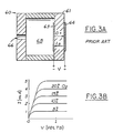
- single ZrO2 cell device 60 of Figure 3A which is useful as a lean O2-sensor. It has a single oxygen pumping cell 61 made from a ZrO2 platelet with two platinum electrodes 63 and 64 arranged in a structure so that a volume 65 is defined. Volume 65 communicates with the ambient gas through an aperture 66. When a voltage is applied across cell 61 so that electrode 63 is negative, a current I3 passes through the ZrO2 material as a result of motion of oxygen ions from electrode 63 to electrode 64.
- the single cell device 60 is used to measure the percentage of O2 in an exhaust gas/intake air mixture, for small voltages (0.2-0.8 v) the current increases with voltage as more oxygen is pumped out of volume 65 and reaches a saturation current, I s . This corresponds to the condition that all oxygen inside volume 65 is pumped out by the current.
- the saturation current I s is proportional to the percentage of O2 in the ambient.
- the voltage across the pump cell is maintained below about 0.8 volts so as to not decompose any gas molecules containing O2, such as CO2, present in volume 65.
- the current voltage (I-V) characteristics of single cell prior art device 60 (for various percentages of O2) under these conditions is shown in Figure 3B.
- FIG. 1 The relationship between the percentage of O2 in intake air/exhaust gas mixtures and the percentage of EGR therein is shown in Figure 1.
- Figure 4 shows the same relationship except at lower percentages of O2 inside the volume. It can be seen from these figures that for the same percentage change in O2 at a higher (Fig. 1) and at a lower O2 (Fig. 4) concentration, .PA there is a smaller percentage change in EGR at the lower O2 concentration.
- the prior art single cell device is more sensitive to changes in EGR at low oxygen concentrations than it is at high oxygen concentrations.
- device 61 of Figure 3A can be suitably used for the measurement of EGR in a low-O2 environment, it is not optimally sensitive in high O2 (i.e. low EGR) environments.
- device 20 can be used to measure the percentage of O2 in such a gas mixture.
- the device comprises a first and a second oxygen pump cell.
- the first oxygen pumping cell pumps out a portion (e.g., 1/2) of the oxygen molecules from volume 40 so as to reduce the percentage of O2 molecules in the gas mixture in the volume. This, in effect, modifies the percentage of O2 molecules in the high O2 (20-10%) intake air/exhaust gas mixture of Figure 1 to the lower O2 (10-0%) mixture of that of Figure 4.
- the portion of oxygen molecules is pumped out of volume 40 by passing a constant current through cell 21 so that electrode 24 is negative.
- the current passed through cell 21 is that which is sufficient to cause cell 21 to pump the desired amount (portion) of the O2 molecules out of volume 40.
- the amount of O2 pumped out of volume 40 by the first oxygen pump cell 21 equals the percentage of O2 (by volume) present in the intake air/exhaust gas mixture, of the particular internal combustion engine being measured, at the maximum percentage of EGR employed (by that engine).
- removing 1/2 (50% by volume) of the O2 as in the embodiment above would be optimal for an engine in which the maximum amount of EGR generally employed in the engine gas mixture is 50% by volume since it contains about 50% by volume O2.
- cell 21 of the device would optimally remove 70% by volume of the O2 molecules, leaving about 30% of the O2 molecules in volume 41.
- the current necessary to remove the desired portion of O2 molecules from the volume would depend on such factors as the type and dimensions of aperture 41, and temperature. Selection of the optimum current necessary to pump the desired portion of the O2 molecules out of volume 40 by means of cell 21 will be apparent to those skilled in the art in view of the present disclosure.
- the percentage of O2 in the reduced oxygen mixture inside volume 40 is measured by the second oxygen pump cell 31.
- a constant voltage of less than 0.8 volts, generally between 0.2 and 0.8 volts, is applied across the second oxygen pump cell 31 of the invention device of Figure 2, with electrode 33 being negatively biased, to pump out substantially the remainder of O2 molecules inside volume 40.
- the voltage across the pump cell is maintained below about 0.8 volts so as to not decompose any gas molecules containing O2, such as CO2, present in volume 40.
- a saturation current is achieved in cell 31.
- An external circuit means coupled to pump cell 31 is used to measure the saturation current flowing through the second pump cell 31. This saturation current, I s , is a measure of the percentage of O2 molecules in the volume 40 and also is proportional to the percentage of O2 molecules in the intake air and exhaust gas mixture.
- the reduced-O2 mixture inside volume 40 (effected by the pumping out of a portion of the O2 molecules from volume 40 by cell 21) simulates a low-O2 mixture.
- This allows the device to measure the percentage of O2 in a high-O2 mixture with the sensitivity obtained when measuring low-O2 mixtures.
- the device of this invention provides a more sensitive measurement of EGR in a high-O2 intake air/exhaust gas mixture as compared to that obtained by the single O2 pumping prior art device 3A.
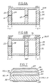
- the device of Figure 2 operates under the assumption that cell 21 can pump the desired portion of oxygen entering volume 40 through aperture 41 so that only the remainder of the O2 reaches cell 31. If this is not the case with the device structure of Figure 2, the desired condition can be accomplished by modifying its structure to that of device 50 as shown in Figure 5.
- a porous layer 38 is deposited on top of the inner electrode of cell 31.
- This porous layer is made from ZrO2 or an inert material (e.g. spinel or aluminium oxide) and acts as a hindrance (barrier) to O2 diffusion so that the desired portion of O2 is pumped out by cell 21.
- the two pumping cells are more strongly decoupled by placing between them barriers to oxygen diffusion.
- the porous layer in the device of Figure 5 may be replaced with a "wall" 42 having an aperture 43 as shown in device 50A of Figure 6A.
- Another type of configuration is shown in device 50B of Figure 6B.
- Device 50B uses a pump cell to remove a portion of the O2 and a pump cell/sensor cell structure 70 (similar to the sensor structure described in U.S. 4.272,329 by Hetrick et al) to remove and measure the remaining O2.
- FIG. 7 shows one embodiment of a planar device 80 according to this invention.
- a dense ZrO2 platelet 82 deposits porous platinum electrodes 83 and 84 on both sides of platelet 82 to form pump cell 81.
- a porous layer 89 made of ZrO2 or an inert material e.g. spinel or aluminium oxide
- a porous platinum electrode 85 is deposited on layer 89 followed by another porous layer 86 of ZrO2.
- a porous platinum electrode 87 is deposited on top of layer 86.
- Porous ZrO2 layer 86 and platinum electrodes 85 and 87 form pump cell 88.
- a constant current is passed through pump cell 88 to pump a portion of the oxygen out of the porous parts of the structure, and a constant voltage of between about 0.2 and 0.8 volts is applied across pump cell 81 to pump out substantially all of the remaining O2 inside the porous layer 89.
- the saturation current of pump cell 81 is proportional to the percentage of EGR in the gas mixture.
Applications Claiming Priority (2)
| Application Number | Priority Date | Filing Date | Title |
|---|---|---|---|
| US07/222,864 US4909072A (en) | 1988-07-22 | 1988-07-22 | Measurement and control of exhaust gas recirculation with an oxygen pumping device |
| US222864 | 1988-07-22 |
Publications (3)
| Publication Number | Publication Date |
|---|---|
| EP0351960A2 true EP0351960A2 (de) | 1990-01-24 |
| EP0351960A3 EP0351960A3 (de) | 1991-04-10 |
| EP0351960B1 EP0351960B1 (de) | 1994-08-31 |
Family
ID=22834043
Family Applications (1)
| Application Number | Title | Priority Date | Filing Date |
|---|---|---|---|
| EP89306329A Expired - Lifetime EP0351960B1 (de) | 1988-07-22 | 1989-06-22 | Messung und Kontrolle des Abgaskreislaufs mit einer Sauerstoffpumpvorrichtung |
Country Status (5)
| Country | Link |
|---|---|
| US (1) | US4909072A (de) |
| EP (1) | EP0351960B1 (de) |
| JP (1) | JPH0274857A (de) |
| CA (1) | CA1295366C (de) |
| DE (1) | DE68917821T2 (de) |
Cited By (6)
| Publication number | Priority date | Publication date | Assignee | Title |
|---|---|---|---|---|
| WO1994004913A1 (de) * | 1992-08-11 | 1994-03-03 | Robert Bosch Gmbh | Polarographischer sensor |
| EP0791828A1 (de) * | 1996-02-23 | 1997-08-27 | Ngk Insulators, Ltd. | Verfahren zur Bestimmung von Stickstoffoxiden |
| EP0878709A2 (de) * | 1997-03-21 | 1998-11-18 | NGK Spark Plug Co. Ltd. | Verfahren und Vorrichtung zur Messung der Stickstoffoxidkonzentration |
| EP0843084A3 (de) * | 1996-11-14 | 1999-08-04 | Toyota Jidosha Kabushiki Kaisha | Brennkraftmaschine mit Abgasrückführungsvorrichtung |
| EP1014084A2 (de) * | 1996-05-16 | 2000-06-28 | Ngk Insulators, Ltd. | Verfahren zur Bestimmung von Stickoxyd |
| EP1486779A2 (de) * | 1994-04-21 | 2004-12-15 | Ngk Insulators, Ltd. | NOx Sensor |
Families Citing this family (18)
| Publication number | Priority date | Publication date | Assignee | Title |
|---|---|---|---|---|
| US5049254A (en) * | 1987-05-29 | 1991-09-17 | Ford Motor Company | Exhaust gas recirculation sensor |
| US5221445A (en) * | 1989-04-17 | 1993-06-22 | Gte Laboratories Incorporated | Method for determining identification and concentration of an atmospheric component |
| US5034107A (en) * | 1989-12-12 | 1991-07-23 | Gte Laboratories Incorporated | Method for sensing nitrous oxide |
| US5080765A (en) * | 1989-12-20 | 1992-01-14 | Gte Laboratories Incorporated | Method for determining identification and concentration of an atmospheric component |
| FR2667113B1 (fr) * | 1990-09-26 | 1993-06-25 | Semt Pielstick | Procede de surveillance de l'emission d'oxydes d'azote par un moteur a combustion interne. |
| DE4039429A1 (de) * | 1990-12-11 | 1992-06-17 | Abb Patent Gmbh | Verfahren und vorrichtung zur ueberpruefung eines katalysators |
| US5217588A (en) * | 1992-02-27 | 1993-06-08 | Gte Laboratories Incorporated | Method and apparatus for sensing NOx |
| US5672811A (en) * | 1994-04-21 | 1997-09-30 | Ngk Insulators, Ltd. | Method of measuring a gas component and sensing device for measuring the gas component |
| DE4447033C2 (de) * | 1994-12-28 | 1998-04-30 | Bosch Gmbh Robert | Meßfühler zur Bestimmung des Sauerstoffgehaltes in Gasgemischen |
| JP3501189B2 (ja) * | 1995-06-07 | 2004-03-02 | 株式会社デンソー | 空燃比センサ素子 |
| US6051123A (en) * | 1995-06-15 | 2000-04-18 | Gas Research Institute | Multi-functional and NOx sensor for combustion systems |
| JP3332761B2 (ja) * | 1996-11-08 | 2002-10-07 | 日本特殊陶業株式会社 | 酸素濃度・窒素酸化物濃度測定方法及び装置 |
| DE69703018T2 (de) | 1996-12-02 | 2001-05-03 | Ngk Spark Plug Co | Verfahren und Vorrichtung zur Messung der Stickstoffoxidkonzentration |
| US6695964B1 (en) | 1996-12-02 | 2004-02-24 | Ngk Spark Plug Co., Ltd. | Method and apparatus for measuring NOx gas concentration |
| US6228252B1 (en) | 1997-02-13 | 2001-05-08 | Ngk Spark Plug Co. Ltd. | Apparatus for detecting concentration of nitrogen oxide |
| US6344134B1 (en) | 1998-01-16 | 2002-02-05 | Ngk Spark Plug Co., Ltd. | Method for measuring NOx concentration and NOx concentration sensor |
| DE202013103647U1 (de) | 2013-08-12 | 2013-09-02 | Aspect Imaging Ltd. | Ein System zum Online-Messen und Steuern von O2-Fraktion, CO-Fraktion und CO2-Fraktion |
| JP6141746B2 (ja) * | 2013-10-16 | 2017-06-07 | 日立オートモティブシステムズ株式会社 | 内燃機関の制御装置 |
Citations (7)
| Publication number | Priority date | Publication date | Assignee | Title |
|---|---|---|---|---|
| US4272331A (en) * | 1980-03-03 | 1981-06-09 | Ford Motor Company | Oscillatory mode oxygen sensor and method |
| EP0123720A1 (de) * | 1983-03-29 | 1984-11-07 | NGK Spark Plug Co. Ltd. | Sauerstoffühler |
| WO1985000659A1 (en) * | 1983-07-18 | 1985-02-14 | Ford Motor Company | Measuring an extended range of air fuel ratio |
| EP0147233A2 (de) * | 1983-12-27 | 1985-07-03 | Mitsubishi Denki Kabushiki Kaisha | Rückfuhrsteuerungssystem für Abgase |
| DE3515588A1 (de) * | 1984-05-01 | 1985-11-07 | Nissan Motor Co., Ltd., Yokohama, Kanagawa | Luft/kraftstoff-verhaeltnis-detektor und diesen enthaldendes regelsystem |
| EP0194082A1 (de) * | 1985-02-23 | 1986-09-10 | Ngk Insulators, Ltd. | Verfahren zur Konzentrationsbestimmung einer Komponente in Gasen und elektrochemische Einrichtung, geeignet zur Durchführung des Verfahrens |
| DE3627227A1 (de) * | 1985-08-10 | 1987-02-19 | Honda Motor Co Ltd | Sauerstoffkonzentrations-detektoranordnung |
Family Cites Families (10)
| Publication number | Priority date | Publication date | Assignee | Title |
|---|---|---|---|---|
| US4272330A (en) * | 1980-03-03 | 1981-06-09 | Ford Motor Company | Transient mode oxygen sensor and method |
| US4272329A (en) * | 1980-03-03 | 1981-06-09 | Ford Motor Company | Steady state mode oxygen sensor and method |
| US4487680A (en) * | 1983-04-18 | 1984-12-11 | Ford Motor Company | Planar ZrO2 oxygen pumping sensor |
| JPS60259948A (ja) * | 1984-06-06 | 1985-12-23 | Ngk Insulators Ltd | 電気化学的装置 |
| US4547281A (en) * | 1983-11-21 | 1985-10-15 | Gte Laboratories Incorporated | Gas analysis apparatus |
| US4578172A (en) * | 1983-12-15 | 1986-03-25 | Ngk Spark Plug Co. | Air/fuel ratio detector |
| JPS60192250A (ja) * | 1984-03-13 | 1985-09-30 | Ngk Spark Plug Co Ltd | 酸素センサ |
| US4568443A (en) * | 1984-09-06 | 1986-02-04 | Mitsubishi Denki Kabushiki Kaisha | Air-to-fuel ratio sensor |
| JPH0680427B2 (ja) * | 1985-09-10 | 1994-10-12 | 日本電装株式会社 | ポンプ式酸素濃度検出装置 |
| GB2183042B (en) * | 1985-09-27 | 1989-09-20 | Ngk Spark Plug Co | Air/fuel ratio sensor |
-
1988
- 1988-07-22 US US07/222,864 patent/US4909072A/en not_active Expired - Lifetime
-
1989
- 1989-06-14 CA CA000602757A patent/CA1295366C/en not_active Expired - Lifetime
- 1989-06-22 DE DE68917821T patent/DE68917821T2/de not_active Expired - Lifetime
- 1989-06-22 EP EP89306329A patent/EP0351960B1/de not_active Expired - Lifetime
- 1989-07-20 JP JP1188679A patent/JPH0274857A/ja active Pending
Patent Citations (7)
| Publication number | Priority date | Publication date | Assignee | Title |
|---|---|---|---|---|
| US4272331A (en) * | 1980-03-03 | 1981-06-09 | Ford Motor Company | Oscillatory mode oxygen sensor and method |
| EP0123720A1 (de) * | 1983-03-29 | 1984-11-07 | NGK Spark Plug Co. Ltd. | Sauerstoffühler |
| WO1985000659A1 (en) * | 1983-07-18 | 1985-02-14 | Ford Motor Company | Measuring an extended range of air fuel ratio |
| EP0147233A2 (de) * | 1983-12-27 | 1985-07-03 | Mitsubishi Denki Kabushiki Kaisha | Rückfuhrsteuerungssystem für Abgase |
| DE3515588A1 (de) * | 1984-05-01 | 1985-11-07 | Nissan Motor Co., Ltd., Yokohama, Kanagawa | Luft/kraftstoff-verhaeltnis-detektor und diesen enthaldendes regelsystem |
| EP0194082A1 (de) * | 1985-02-23 | 1986-09-10 | Ngk Insulators, Ltd. | Verfahren zur Konzentrationsbestimmung einer Komponente in Gasen und elektrochemische Einrichtung, geeignet zur Durchführung des Verfahrens |
| DE3627227A1 (de) * | 1985-08-10 | 1987-02-19 | Honda Motor Co Ltd | Sauerstoffkonzentrations-detektoranordnung |
Non-Patent Citations (1)
| Title |
|---|
| SAE INTERNATIONAL CONGRESS AND EXPOSITION, 29th February - 4th March 1988, Technical Paper no. 880133; M. NISHIDA et al.: "Closed loop control of the EGR rate using the oxygen sensor" * |
Cited By (19)
| Publication number | Priority date | Publication date | Assignee | Title |
|---|---|---|---|---|
| WO1994004913A1 (de) * | 1992-08-11 | 1994-03-03 | Robert Bosch Gmbh | Polarographischer sensor |
| EP1486779A3 (de) * | 1994-04-21 | 2004-12-22 | Ngk Insulators, Ltd. | NOx Sensor |
| EP1486779A2 (de) * | 1994-04-21 | 2004-12-15 | Ngk Insulators, Ltd. | NOx Sensor |
| EP0791828A1 (de) * | 1996-02-23 | 1997-08-27 | Ngk Insulators, Ltd. | Verfahren zur Bestimmung von Stickstoffoxiden |
| EP1014084A3 (de) * | 1996-05-16 | 2000-09-20 | Ngk Insulators, Ltd. | Verfahren zur Bestimmung von Stickoxyd |
| US6306271B1 (en) | 1996-05-16 | 2001-10-23 | Ngk Insulators, Ltd. | Sensor for measuring nitrogen oxide |
| EP1014084A2 (de) * | 1996-05-16 | 2000-06-28 | Ngk Insulators, Ltd. | Verfahren zur Bestimmung von Stickoxyd |
| EP1439290A2 (de) | 1996-11-14 | 2004-07-21 | Toyota Jidosha Kabushiki Kaisha | Brennkraftmaschine mit Abgasrückführeinrichtung |
| US6000385A (en) * | 1996-11-14 | 1999-12-14 | Toyota Jidosha Kabushiki Kaisha | Combustion engine with EGR apparatus |
| EP0843084A3 (de) * | 1996-11-14 | 1999-08-04 | Toyota Jidosha Kabushiki Kaisha | Brennkraftmaschine mit Abgasrückführungsvorrichtung |
| EP1439291A2 (de) | 1996-11-14 | 2004-07-21 | Toyota Jidosha Kabushiki Kaisha | Brennkraftmaschine mit Abgasrückführungsvorrichtung |
| EP1439290A3 (de) * | 1996-11-14 | 2006-08-02 | Toyota Jidosha Kabushiki Kaisha | Brennkraftmaschine mit Abgasrückführeinrichtung |
| EP1439291A3 (de) * | 1996-11-14 | 2006-08-02 | Toyota Jidosha Kabushiki Kaisha | Brennkraftmaschine mit Abgasrückführungsvorrichtung |
| EP1077375A1 (de) | 1997-03-21 | 2001-02-21 | Ngk Spark Plug Co., Ltd | Verfahren und Vorrichtung zur Messung der Stickstoffoxidkonzentration |
| US6375828B2 (en) | 1997-03-21 | 2002-04-23 | Ngk Spark Plug Co., Ltd. | Methods and apparatus for measuring NOx gas concentration, for detecting exhaust gas concentration and for calibrating and controlling gas sensor |
| US6743352B2 (en) | 1997-03-21 | 2004-06-01 | Ngk Spark Plug Co., Ltd. | Method and apparatus for correcting a gas sensor response for moisture in exhaust gas |
| EP0878709A3 (de) * | 1997-03-21 | 1999-04-28 | NGK Spark Plug Co. Ltd. | Verfahren und Vorrichtung zur Messung der Stickstoffoxidkonzentration |
| EP0878709A2 (de) * | 1997-03-21 | 1998-11-18 | NGK Spark Plug Co. Ltd. | Verfahren und Vorrichtung zur Messung der Stickstoffoxidkonzentration |
| US6923902B2 (en) | 1997-03-21 | 2005-08-02 | Ngk Spark Plug Co, Ltd. | Methods and apparatus for measuring NOx gas concentration, for detecting exhaust gas concentration and for calibrating and controlling gas sensor |
Also Published As
| Publication number | Publication date |
|---|---|
| DE68917821T2 (de) | 1994-12-22 |
| CA1295366C (en) | 1992-02-04 |
| EP0351960B1 (de) | 1994-08-31 |
| US4909072A (en) | 1990-03-20 |
| JPH0274857A (ja) | 1990-03-14 |
| EP0351960A3 (de) | 1991-04-10 |
| DE68917821D1 (de) | 1994-10-06 |
Similar Documents
| Publication | Publication Date | Title |
|---|---|---|
| EP0351960B1 (de) | Messung und Kontrolle des Abgaskreislaufs mit einer Sauerstoffpumpvorrichtung | |
| US5145566A (en) | Method for determining relative amount of oxygen containing gas in a gas mixture | |
| EP0361692B1 (de) | Sensor zur Bestimmung der relativen Quantität von einem Sauerstoff enthaltenden Gas in einer Gasmischung | |
| US4487680A (en) | Planar ZrO2 oxygen pumping sensor | |
| US6196053B1 (en) | Method of measuring a gas component and sensing device for measuring the gas component | |
| EP0580206B1 (de) | Sauerstoffsensor mit einem breiten Bereich | |
| US5089113A (en) | Measurement and control of exhaust gas recirculation with an oxygen pumping device | |
| US4574627A (en) | Air-fuel ratio detector and method of measuring air-fuel ratio | |
| US4720335A (en) | Wide range air fuel ratio sensor | |
| US5049254A (en) | Exhaust gas recirculation sensor | |
| US4568443A (en) | Air-to-fuel ratio sensor | |
| US5879526A (en) | Electrochemical measuring sensor for determining nitrogen oxides in gas mixtures | |
| EP0709668A2 (de) | Verfahren und Vorrichtung zur Bestimmung der Konzentration von Gaskomponenten | |
| US20100126883A1 (en) | Sensor element having suppressed rich gas reaction | |
| EP0227257B1 (de) | Elektrochemische Vorrichtung | |
| JPH09507916A (ja) | 混合気中の窒素酸化物を測定するための電気化学センサ | |
| US5010762A (en) | Measurement and control of exhaust gas recirculation with an oxygen pumping device | |
| US4841934A (en) | Oxygen pumping device for control of the air fuel ratio | |
| US4770758A (en) | Air/fuel ratio detector | |
| US4666566A (en) | Method of detecting oxygen partial pressure | |
| US20030106795A1 (en) | Gas sensing element | |
| US20030062904A1 (en) | Error minimizing structure of gas sensor | |
| JPH0412420B2 (de) | ||
| Logothetis | Air‐To‐Fuel Sensors Based on Oxygen Pumping | |
| Oh | A planar-type sensor for detection of oxidizing and reducing gases |
Legal Events
| Date | Code | Title | Description |
|---|---|---|---|
| PUAI | Public reference made under article 153(3) epc to a published international application that has entered the european phase |
Free format text: ORIGINAL CODE: 0009012 |
|
| AK | Designated contracting states |
Kind code of ref document: A2 Designated state(s): DE FR GB |
|
| PUAL | Search report despatched |
Free format text: ORIGINAL CODE: 0009013 |
|
| AK | Designated contracting states |
Kind code of ref document: A3 Designated state(s): DE FR GB |
|
| 17P | Request for examination filed |
Effective date: 19910928 |
|
| 17Q | First examination report despatched |
Effective date: 19930604 |
|
| GRAA | (expected) grant |
Free format text: ORIGINAL CODE: 0009210 |
|
| AK | Designated contracting states |
Kind code of ref document: B1 Designated state(s): DE FR GB |
|
| ET | Fr: translation filed | ||
| REF | Corresponds to: |
Ref document number: 68917821 Country of ref document: DE Date of ref document: 19941006 |
|
| PLBE | No opposition filed within time limit |
Free format text: ORIGINAL CODE: 0009261 |
|
| STAA | Information on the status of an ep patent application or granted ep patent |
Free format text: STATUS: NO OPPOSITION FILED WITHIN TIME LIMIT |
|
| 26N | No opposition filed | ||
| REG | Reference to a national code |
Ref country code: FR Ref legal event code: TP Ref country code: FR Ref legal event code: CD |
|
| REG | Reference to a national code |
Ref country code: GB Ref legal event code: IF02 |
|
| REG | Reference to a national code |
Ref country code: GB Ref legal event code: 746 Effective date: 20050112 |
|
| REG | Reference to a national code |
Ref country code: FR Ref legal event code: CD Ref country code: FR Ref legal event code: CA |
|
| PGFP | Annual fee paid to national office [announced via postgrant information from national office to epo] |
Ref country code: DE Payment date: 20080630 Year of fee payment: 20 |
|
| PGFP | Annual fee paid to national office [announced via postgrant information from national office to epo] |
Ref country code: GB Payment date: 20080506 Year of fee payment: 20 |
|
| REG | Reference to a national code |
Ref country code: GB Ref legal event code: PE20 Expiry date: 20090621 |
|
| PG25 | Lapsed in a contracting state [announced via postgrant information from national office to epo] |
Ref country code: GB Free format text: LAPSE BECAUSE OF EXPIRATION OF PROTECTION Effective date: 20090621 |
|
| PGFP | Annual fee paid to national office [announced via postgrant information from national office to epo] |
Ref country code: FR Payment date: 20080424 Year of fee payment: 20 |