EP0351872B1 - Cleaner for filler nozzles - Google Patents
Cleaner for filler nozzles Download PDFInfo
- Publication number
- EP0351872B1 EP0351872B1 EP89113446A EP89113446A EP0351872B1 EP 0351872 B1 EP0351872 B1 EP 0351872B1 EP 89113446 A EP89113446 A EP 89113446A EP 89113446 A EP89113446 A EP 89113446A EP 0351872 B1 EP0351872 B1 EP 0351872B1
- Authority
- EP
- European Patent Office
- Prior art keywords
- manifold
- filler
- shelf
- seal
- invention according
- Prior art date
- Legal status (The legal status is an assumption and is not a legal conclusion. Google has not performed a legal analysis and makes no representation as to the accuracy of the status listed.)
- Expired - Lifetime
Links
- 239000000945 filler Substances 0.000 title claims abstract description 27
- 230000000295 complement effect Effects 0.000 claims description 2
- 238000000151 deposition Methods 0.000 claims 1
- 238000004140 cleaning Methods 0.000 description 4
- 239000007788 liquid Substances 0.000 description 4
- 239000000463 material Substances 0.000 description 4
- 239000000047 product Substances 0.000 description 4
- 238000011109 contamination Methods 0.000 description 3
- 238000007789 sealing Methods 0.000 description 2
- 239000007787 solid Substances 0.000 description 2
- 239000004698 Polyethylene Substances 0.000 description 1
- 239000004699 Ultra-high molecular weight polyethylene Substances 0.000 description 1
- 239000006227 byproduct Substances 0.000 description 1
- 239000011344 liquid material Substances 0.000 description 1
- 238000004519 manufacturing process Methods 0.000 description 1
- 239000002245 particle Substances 0.000 description 1
- -1 polyethylene Polymers 0.000 description 1
- 229920000573 polyethylene Polymers 0.000 description 1
- 239000011343 solid material Substances 0.000 description 1
- 229910001220 stainless steel Inorganic materials 0.000 description 1
- 239000010935 stainless steel Substances 0.000 description 1
- 229920000785 ultra high molecular weight polyethylene Polymers 0.000 description 1
Images
Classifications
-
- B—PERFORMING OPERATIONS; TRANSPORTING
- B67—OPENING, CLOSING OR CLEANING BOTTLES, JARS OR SIMILAR CONTAINERS; LIQUID HANDLING
- B67C—CLEANING, FILLING WITH LIQUIDS OR SEMILIQUIDS, OR EMPTYING, OF BOTTLES, JARS, CANS, CASKS, BARRELS, OR SIMILAR CONTAINERS, NOT OTHERWISE PROVIDED FOR; FUNNELS
- B67C3/00—Bottling liquids or semiliquids; Filling jars or cans with liquids or semiliquids using bottling or like apparatus; Filling casks or barrels with liquids or semiliquids
- B67C3/001—Cleaning of filling devices
- B67C3/002—Cleaning of filling devices using cups or dummies to be placed under the filling heads
- B67C3/004—Cleaning of filling devices using cups or dummies to be placed under the filling heads permanently attached to the filling machine and movable between a rest and a working position
-
- B—PERFORMING OPERATIONS; TRANSPORTING
- B65—CONVEYING; PACKING; STORING; HANDLING THIN OR FILAMENTARY MATERIAL
- B65B—MACHINES, APPARATUS OR DEVICES FOR, OR METHODS OF, PACKAGING ARTICLES OR MATERIALS; UNPACKING
- B65B39/00—Nozzles, funnels or guides for introducing articles or materials into containers or wrappers
- B65B39/14—Nozzles, funnels or guides for introducing articles or materials into containers or wrappers movable with a moving container or wrapper during filling or depositing
- B65B39/145—Nozzles, funnels or guides for introducing articles or materials into containers or wrappers movable with a moving container or wrapper during filling or depositing in an endless path
Definitions
- This invention relates to a cleaner for filler nozzles, and more particularly to such a cleaner which removes excess product from the filler nozzles during operation of the filler.
- a filler places product, such as food stuffs, into containers, which are then sealed by lids. Contamination of the sealing area by product falling onto, or otherwise contacting, this area will render the seal between the lid and the container ineffective, and hence, the resulting package unuseable. It is important, therefore, to maintain the seal area of the container free from contamination.
- GB-A-2 002 331 discloses a nozzle-wiper assembly for an apparatus for filling containers with liquid.
- This apparatus comprises a tubular nozzle having slidably mounted thereon a ring member which has at least one passage. So the central opening of the ring member can be subjected to sub-atmospheric pressure to suck off any liquid adhering to the outer surface of the nozzle tube as the tube and the ring member slide relative to each other.
- the present invention provides a means which maintains the seal area of containers free from contamination, which controls both solid and liquid and thus is especially useful with piston-type fillers, which may be quickly and easily removed from the filler for cleaning and then just as quickly and easily replaced, which is reliable and which is relatively economical to manufacture and maintain.
- a piston filler indicated generally at 10, which may be a C-series M&S piston filler, for example.
- the filler 10 typically has a plurality of pistons reciprocable in cylinders 12 equiangularly positioned around the periphery thereof.
- the pistons are moved upward as the filler 10 is rotated about its vertical axis 14 to fill the cylinders 12 with product which is then discharged through a nozzle 16, shown in Figures 2 and 3, formed at the lower end of each cylinder.
- a chain 18 engages a gear 20 attached to the filler 10 and carries containers 22 past the filler. The chain and gear cooperate to position each container 22 under a cylinder 12 so that product discharged from the associated nozzle 16 is received by the container.
- a plurality of arcuate vacuum seal blocks 24 are arranged around the periphery of the filler 10 to form an upper vacuum seal 26.
- Each block 24 extends between two adjacent cylinders 12 and is formed with a semicircular notch 28 at each end to engage the cylinders.
- Each block 24 is secured in place by four set screws 30, 32, 34 and 36 which extend through threaded holes 38 in the block and engage an annular groove 40 formed in the lower end of the cylinders 12.
- the circumferential ends of each block abut the adjacent ends of the blocks on each side thereof and completely encircle the cylinders 12 to form the circular upper vacuum seal 26.
- a circumferential groove 42 is formed in the lower surface of each block 24 to provide clearance for the lower end of the nozzle 16.
- a seal plate 44 is secured to a manifold 46 by a plurality of bolts 48.
- the manifold 46 is supported on a stationery shelf 50 attached to a non-rotating portion of the filler.
- the shelf 50 has a pair of T-shaped lugs 52 and 54 attached to its upper surface.
- the lugs 52 and 54 mate with a pair of complementary T-shaped grooves 56 and 58 formed in the manifold 46.
- the manifold 46, and the attached seal plate 44 can be positioned with the grooves 56 and 58 aligned with the lugs 52 and 54 and then pushed toward the filler 10 until the manifold 46 contacts plates 60 attached at the inner edge of the shelf 50 and the lugs 52 and 54.
- the plates 60 position the seal plate 44 radially so that it is under the upper seal 26.
- the manifold 46 is held in this position by a pair of lock bars 62 affixed to the end of a headed lock rods 64.
- the rods 64 extend through holes 66 of a diameter smaller than the head but larger than the rod itself in the manifold 46. Turning the rod 64 so that the lock bar 62 is behind the shelf 50 will secure the manifold 46 and the seal plate 44 to the shelf 50.
- the manifold 46 and seal plate 44 can be readily removed for cleaning by simply turning the rods 64 to position the lock bar 62 to clear the shelf 50, as shown in Figure 3 and 4.
- the manifold 46 has a central cavity 70 which communicates with a vacuum tube 72, which is connected at its outer end with a vacuum source.
- the tube 72 is seated in a blind cylindrical hole 74 extending through the outer side of the manifold 46 and across the cavity 70 with its centerline positioned substantially in the plane of the lower surface of cavity 70.
- the tube 72 has a slot 76 extending transverse to the centerline of the tube and a width substantially equal to the width of the cavity 70.
- the bottom of the slot 76 is level with the bottom of the cavity 70 so that any material entering the cavity may be drawn into the tube 72 through the slot 76.
- the hole 74 extends partially through the inner wall of the manifold 46 and provides a seat, and thus stability, for the tube 72.
- the seal plate 44 is sealed to the manifold 46 by the bolts 48 and has arcuate extensions 82 and 84 on each end which extend under the upper seal 26 and form a flow chamber 85 with the grooves 42.
- a pair of holes 86 and 88 in the seal plate 44 are positioned to provide communication with each end of the cavity 70 in the manifold 46 and the flow chamber 85.
- the free end of the extension 82 is beveled at 90 to direct air flow, as a result of the vacuum, upward into the chamber 85, and is positioned to be adjacent the exit of the chain 18 from the filler 10. Thus, any liquid dripping from the nozzle 16 that has just filled a container would be sucked into the chamber 85 by the air flow.
- any solid particles clinging to the nozzle or strings trailing therefrom will be drawn into the chamber 85.
- Any drips of liquid or solid material falling from the nozzle 16 after it has passed the manifold 46 will be caught by the extension 84.
- the air flow relative to the nozzle 16 increases over the extension 84 because the velocity of the air flow is added to the velocity of the nozzle due to rotation of the filler.
- the cleaning action is, therefore, efficient and minimizes the possibility of material being dropped onto the sealing lip of a container during its entrance to the filler.
- the entire manifold 46 and seal plate 44 may be removed quickly and easily for cleaning.
- the manifold 46, and blocks 24 are preferrable made from a polyethylene material, such as ultra high molecular weight polyethylene and the seal plate 44 from stainless steel, which materials are suitable for use with food stuffs.
Landscapes
- Engineering & Computer Science (AREA)
- Mechanical Engineering (AREA)
- Filling Of Jars Or Cans And Processes For Cleaning And Sealing Jars (AREA)
- Vacuum Packaging (AREA)
- Nozzles (AREA)
- Basic Packing Technique (AREA)
- Supply Of Fluid Materials To The Packaging Location (AREA)
- Detergent Compositions (AREA)
Abstract
Description
- This invention relates to a cleaner for filler nozzles, and more particularly to such a cleaner which removes excess product from the filler nozzles during operation of the filler.
- A filler places product, such as food stuffs, into containers, which are then sealed by lids. Contamination of the sealing area by product falling onto, or otherwise contacting, this area will render the seal between the lid and the container ineffective, and hence, the resulting package unuseable. It is important, therefore, to maintain the seal area of the container free from contamination.
- GB-A-2 002 331 discloses a nozzle-wiper assembly for an apparatus for filling containers with liquid. This apparatus comprises a tubular nozzle having slidably mounted thereon a ring member which has at least one passage. So the central opening of the ring member can be subjected to sub-atmospheric pressure to suck off any liquid adhering to the outer surface of the nozzle tube as the tube and the ring member slide relative to each other.
- The present invention provides a means which maintains the seal area of containers free from contamination, which controls both solid and liquid and thus is especially useful with piston-type fillers, which may be quickly and easily removed from the filler for cleaning and then just as quickly and easily replaced, which is reliable and which is relatively economical to manufacture and maintain.
- Those and other advantages of the present invention will become more readily apparent from a perusal of the following detailed description of a preferred embodiment and the accompanying drawing, wherein:
- Fig. 1
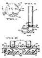
- is a horizontal section representation of a piston-type filler incorporating the present invention;
- Fig. 2
- is a sectional view taken on line 2-2 of Fig. 1;
- Fig. 3
- is a sectional view taken on line 3-3 of Fig. 2; and
- Figure 4
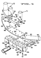
- is an expanded view of the structure shown in Figures 2 and 3.
- Referring now to Figure 1, there is shown a piston filler, indicated generally at 10, which may be a C-series M&S piston filler, for example. The
filler 10 typically has a plurality of pistons reciprocable incylinders 12 equiangularly positioned around the periphery thereof. The pistons are moved upward as thefiller 10 is rotated about itsvertical axis 14 to fill thecylinders 12 with product which is then discharged through anozzle 16, shown in Figures 2 and 3, formed at the lower end of each cylinder. Achain 18 engages agear 20 attached to thefiller 10 and carriescontainers 22 past the filler. The chain and gear cooperate to position eachcontainer 22 under acylinder 12 so that product discharged from the associatednozzle 16 is received by the container. - A plurality of arcuate
vacuum seal blocks 24 are arranged around the periphery of thefiller 10 to form anupper vacuum seal 26. Eachblock 24 extends between twoadjacent cylinders 12 and is formed with asemicircular notch 28 at each end to engage the cylinders. Eachblock 24 is secured in place by fourset screws holes 38 in the block and engage anannular groove 40 formed in the lower end of thecylinders 12. The circumferential ends of each block abut the adjacent ends of the blocks on each side thereof and completely encircle thecylinders 12 to form the circularupper vacuum seal 26. Acircumferential groove 42 is formed in the lower surface of eachblock 24 to provide clearance for the lower end of thenozzle 16. - A
seal plate 44 is secured to amanifold 46 by a plurality ofbolts 48. Themanifold 46 is supported on astationery shelf 50 attached to a non-rotating portion of the filler. Theshelf 50 has a pair of T-shaped lugs lugs shaped grooves manifold 46. Themanifold 46, and the attachedseal plate 44, can be positioned with thegrooves lugs filler 10 until themanifold 46contacts plates 60 attached at the inner edge of theshelf 50 and thelugs plates 60 position theseal plate 44 radially so that it is under theupper seal 26. Themanifold 46 is held in this position by a pair oflock bars 62 affixed to the end of aheaded lock rods 64. Therods 64 extend throughholes 66 of a diameter smaller than the head but larger than the rod itself in themanifold 46. Turning therod 64 so that thelock bar 62 is behind theshelf 50 will secure themanifold 46 and theseal plate 44 to theshelf 50. Themanifold 46 andseal plate 44 can be readily removed for cleaning by simply turning therods 64 to position thelock bar 62 to clear theshelf 50, as shown in Figure 3 and 4. - The
manifold 46 has acentral cavity 70 which communicates with avacuum tube 72, which is connected at its outer end with a vacuum source. Thetube 72 is seated in a blindcylindrical hole 74 extending through the outer side of themanifold 46 and across thecavity 70 with its centerline positioned substantially in the plane of the lower surface ofcavity 70. Thetube 72 has aslot 76 extending transverse to the centerline of the tube and a width substantially equal to the width of thecavity 70. The bottom of theslot 76 is level with the bottom of thecavity 70 so that any material entering the cavity may be drawn into thetube 72 through theslot 76. Thehole 74 extends partially through the inner wall of themanifold 46 and provides a seat, and thus stability, for thetube 72. - The
seal plate 44 is sealed to themanifold 46 by thebolts 48 and hasarcuate extensions upper seal 26 and form aflow chamber 85 with thegrooves 42. A pair ofholes seal plate 44 are positioned to provide communication with each end of thecavity 70 in themanifold 46 and theflow chamber 85. The free end of theextension 82 is beveled at 90 to direct air flow, as a result of the vacuum, upward into thechamber 85, and is positioned to be adjacent the exit of thechain 18 from thefiller 10. Thus, any liquid dripping from thenozzle 16 that has just filled a container would be sucked into thechamber 85 by the air flow. Also, any solid particles clinging to the nozzle or strings trailing therefrom will be drawn into thechamber 85. Any drips of liquid or solid material falling from thenozzle 16 after it has passed themanifold 46 will be caught by theextension 84. The air flow relative to thenozzle 16 increases over theextension 84 because the velocity of the air flow is added to the velocity of the nozzle due to rotation of the filler. The cleaning action is, therefore, efficient and minimizes the possibility of material being dropped onto the sealing lip of a container during its entrance to the filler. Theentire manifold 46 andseal plate 44 may be removed quickly and easily for cleaning. Themanifold 46, andblocks 24 are preferrable made from a polyethylene material, such as ultra high molecular weight polyethylene and theseal plate 44 from stainless steel, which materials are suitable for use with food stuffs.
Claims (6)
- A cleaner for a filler (10) having a plurality of cylinders (12) arranged in a circle and rotatable as a unit about the center (14) thereof, each cylinder having a nozzle (16) at its lower end for depositing product into a container conveyed therewith during a portion of each rotation of said filler; characterized by said cleaner comprising:
a vacuum manifold (46) having a cavity (70) mounted on said filler and fixed against rotation;
means (72) connecting said cavity to a vacuum source;
a seal plate (44) attached to the top of said manifold;
an upper seal means (24, 26) encircling all of said cylinders and rotatable therewith;
a circumferential groove (42) formed in the seal means (24); and
said nozzles (16) being positioned in said groove (42) whereby said vacuum source draws air past said nozzles to cause product on said nozzles to be swept into said cavity. - The invention according to claim 1, and further comprising:
a shelf (50) affixed to said filler (10);
a pair of lugs (52, 54) on said shelf (50);
said manifold (46) having slots (56, 58) completementary to and engageable with said lugs (52, 54);
a plate (60) at the end of each lug (52, 54) to position said manifold (46) radially of said filler (10); and
means (62, 64) securing said manifold (46) against said plates. - The invention according to claim 1, wherein said upper seal is formed by a plurality of seal blocks (24);
each seal block (24) extending between and engaging adjacent ones of said cylinders (12). - The invention according to claim 1, wherein said seal plate (44) includes an extension (82, 84) on each end; and
each extension (82, 84) extends radially beyond said manifold (46). - The invention according to claim 4, wherein the free ends of said extension includes an angled portion (90) to direct air flow upward into said flow chamber (85).
- The invention according to claim 5 and further comprising:
a shelf (50) affixed to said filler (10);
a pair of lugs (52, 54) affixed to said shelf (50);
said manifold (46) having slots (56, 58) complementary to and engageable with said lugs (52, 54);
limit means (60) on said shelf (50) to radially position said manifold (46); and
quick release means (62, 64) for securing said manifold (46) to said shelf (50).
Priority Applications (1)
| Application Number | Priority Date | Filing Date | Title |
|---|---|---|---|
| AT89113446T ATE87594T1 (en) | 1988-07-21 | 1989-07-21 | CLEANING DEVICE FOR FILLER SPOUTS. |
Applications Claiming Priority (2)
| Application Number | Priority Date | Filing Date | Title |
|---|---|---|---|
| US22245788A | 1988-07-21 | 1988-07-21 | |
| US222457 | 1988-07-21 |
Publications (2)
| Publication Number | Publication Date |
|---|---|
| EP0351872A1 EP0351872A1 (en) | 1990-01-24 |
| EP0351872B1 true EP0351872B1 (en) | 1993-03-31 |
Family
ID=22832290
Family Applications (1)
| Application Number | Title | Priority Date | Filing Date |
|---|---|---|---|
| EP89113446A Expired - Lifetime EP0351872B1 (en) | 1988-07-21 | 1989-07-21 | Cleaner for filler nozzles |
Country Status (7)
| Country | Link |
|---|---|
| EP (1) | EP0351872B1 (en) |
| JP (1) | JPH0659915B2 (en) |
| AT (1) | ATE87594T1 (en) |
| BR (1) | BR8903563A (en) |
| CA (1) | CA1307502C (en) |
| DE (1) | DE68905697T2 (en) |
| ES (1) | ES2041904T3 (en) |
Families Citing this family (3)
| Publication number | Priority date | Publication date | Assignee | Title |
|---|---|---|---|---|
| JPH11165797A (en) * | 1997-12-02 | 1999-06-22 | Shikoku Kakoki Co Ltd | Device and method for cleaning filling nozzle |
| CA2618714C (en) * | 2005-08-08 | 2013-11-05 | Etienne Le Roux | Method and apparatus for automated cleaning of bottling equipment |
| US10988363B1 (en) | 2019-02-06 | 2021-04-27 | Owens-Brockway Glass Container Inc. | System for preventing dripping from nozzles in a container filling system |
Family Cites Families (2)
| Publication number | Priority date | Publication date | Assignee | Title |
|---|---|---|---|---|
| GB2002331A (en) * | 1977-08-09 | 1979-02-21 | Albro Fillers & Eng Co Ltd | Filling-nozzle wipers |
| EP2802009B1 (en) | 2013-05-08 | 2021-03-24 | ams AG | Integrated imaging device for infrared radiation and method of production |
-
1989
- 1989-06-22 JP JP1160614A patent/JPH0659915B2/en not_active Expired - Lifetime
- 1989-06-28 CA CA000604200A patent/CA1307502C/en not_active Expired - Lifetime
- 1989-07-19 BR BR898903563A patent/BR8903563A/en unknown
- 1989-07-21 EP EP89113446A patent/EP0351872B1/en not_active Expired - Lifetime
- 1989-07-21 DE DE8989113446T patent/DE68905697T2/en not_active Expired - Fee Related
- 1989-07-21 ES ES198989113446T patent/ES2041904T3/en not_active Expired - Lifetime
- 1989-07-21 AT AT89113446T patent/ATE87594T1/en not_active IP Right Cessation
Also Published As
| Publication number | Publication date |
|---|---|
| JPH0659915B2 (en) | 1994-08-10 |
| CA1307502C (en) | 1992-09-15 |
| JPH02258590A (en) | 1990-10-19 |
| DE68905697T2 (en) | 1993-07-08 |
| DE68905697D1 (en) | 1993-05-06 |
| BR8903563A (en) | 1990-03-13 |
| EP0351872A1 (en) | 1990-01-24 |
| ES2041904T3 (en) | 1993-12-01 |
| ATE87594T1 (en) | 1993-04-15 |
Similar Documents
| Publication | Publication Date | Title |
|---|---|---|
| US4987934A (en) | Cleaner for filler nozzles | |
| US4236903A (en) | Air cleaner | |
| US3904083A (en) | Self-sealing viscous material dispenser loading apparatus | |
| US6418701B1 (en) | Automated filling machine and method | |
| CA2534786C (en) | Tamper evident fitment assembly | |
| GB2066794A (en) | Plastics bucket; apparatus and method for moulding same | |
| US5195294A (en) | Container filling and sealing system | |
| EP0351872A1 (en) | Cleaner for filler nozzles | |
| KR20200083347A (en) | Container packaging apparatus | |
| US5692631A (en) | Container for transporting, storing and dispensing chemical products | |
| US4307557A (en) | Capping machine for application of sealing caps to bungs of liquid containers | |
| RO116070B1 (en) | REUTILIZING DEVICE FOR DISTRIBUTION OF A VASCOS MATERIAL | |
| US6550643B1 (en) | Dispenser for viscous fluids | |
| US6625961B1 (en) | Multiple station bagging system | |
| CN219136328U (en) | Residual sauce recycling device for rotary fluid filling machine | |
| US2751954A (en) | Flexible container and fittings | |
| US3786614A (en) | Container filling and capping apparatus | |
| EP0114711B1 (en) | Method and apparatus for discharging granular material from a ship or the like | |
| US6782927B2 (en) | Can filler valve wiper mechanism | |
| AU619855B2 (en) | Filling machinery | |
| US3880324A (en) | Paste-liquid dispenser with removable puncture rod | |
| US4187662A (en) | Apparatus for removing pressure sensitive tape from containers | |
| US3592353A (en) | Sealing patch for evaporated milk cans | |
| KR100851209B1 (en) | Filtration device | |
| US4836405A (en) | Container for the reception of a pumpable product |
Legal Events
| Date | Code | Title | Description |
|---|---|---|---|
| PUAI | Public reference made under article 153(3) epc to a published international application that has entered the european phase |
Free format text: ORIGINAL CODE: 0009012 |
|
| AK | Designated contracting states |
Kind code of ref document: A1 Designated state(s): AT BE CH DE ES FR GB IT LI LU NL SE |
|
| 17P | Request for examination filed |
Effective date: 19900712 |
|
| 17Q | First examination report despatched |
Effective date: 19920224 |
|
| ITF | It: translation for a ep patent filed | ||
| GRAA | (expected) grant |
Free format text: ORIGINAL CODE: 0009210 |
|
| AK | Designated contracting states |
Kind code of ref document: B1 Designated state(s): AT BE CH DE ES FR GB IT LI LU NL SE |
|
| PG25 | Lapsed in a contracting state [announced via postgrant information from national office to epo] |
Ref country code: SE Effective date: 19930331 Ref country code: LI Effective date: 19930331 Ref country code: CH Effective date: 19930331 Ref country code: AT Effective date: 19930331 |
|
| REF | Corresponds to: |
Ref document number: 87594 Country of ref document: AT Date of ref document: 19930415 Kind code of ref document: T |
|
| REF | Corresponds to: |
Ref document number: 68905697 Country of ref document: DE Date of ref document: 19930506 |
|
| REG | Reference to a national code |
Ref country code: CH Ref legal event code: PL |
|
| ET | Fr: translation filed | ||
| PG25 | Lapsed in a contracting state [announced via postgrant information from national office to epo] |
Ref country code: LU Free format text: LAPSE BECAUSE OF NON-PAYMENT OF DUE FEES Effective date: 19930731 |
|
| REG | Reference to a national code |
Ref country code: ES Ref legal event code: FG2A Ref document number: 2041904 Country of ref document: ES Kind code of ref document: T3 |
|
| PLBE | No opposition filed within time limit |
Free format text: ORIGINAL CODE: 0009261 |
|
| STAA | Information on the status of an ep patent application or granted ep patent |
Free format text: STATUS: NO OPPOSITION FILED WITHIN TIME LIMIT |
|
| 26N | No opposition filed | ||
| PGFP | Annual fee paid to national office [announced via postgrant information from national office to epo] |
Ref country code: FR Payment date: 19940613 Year of fee payment: 6 |
|
| PGFP | Annual fee paid to national office [announced via postgrant information from national office to epo] |
Ref country code: GB Payment date: 19940620 Year of fee payment: 6 |
|
| PGFP | Annual fee paid to national office [announced via postgrant information from national office to epo] |
Ref country code: DE Payment date: 19940623 Year of fee payment: 6 |
|
| PGFP | Annual fee paid to national office [announced via postgrant information from national office to epo] |
Ref country code: BE Payment date: 19940705 Year of fee payment: 6 |
|
| PGFP | Annual fee paid to national office [announced via postgrant information from national office to epo] |
Ref country code: ES Payment date: 19940708 Year of fee payment: 6 |
|
| PGFP | Annual fee paid to national office [announced via postgrant information from national office to epo] |
Ref country code: NL Payment date: 19940731 Year of fee payment: 6 |
|
| PG25 | Lapsed in a contracting state [announced via postgrant information from national office to epo] |
Ref country code: GB Effective date: 19950721 |
|
| PG25 | Lapsed in a contracting state [announced via postgrant information from national office to epo] |
Ref country code: ES Free format text: LAPSE BECAUSE OF THE APPLICANT RENOUNCES Effective date: 19950722 |
|
| PG25 | Lapsed in a contracting state [announced via postgrant information from national office to epo] |
Ref country code: BE Effective date: 19950731 |
|
| BERE | Be: lapsed |
Owner name: FMC CORP. Effective date: 19950731 |
|
| PG25 | Lapsed in a contracting state [announced via postgrant information from national office to epo] |
Ref country code: NL Effective date: 19960201 |
|
| GBPC | Gb: european patent ceased through non-payment of renewal fee |
Effective date: 19950721 |
|
| NLV4 | Nl: lapsed or anulled due to non-payment of the annual fee |
Effective date: 19960201 |
|
| PG25 | Lapsed in a contracting state [announced via postgrant information from national office to epo] |
Ref country code: DE Effective date: 19960402 |
|
| PG25 | Lapsed in a contracting state [announced via postgrant information from national office to epo] |
Ref country code: FR Effective date: 19960430 |
|
| REG | Reference to a national code |
Ref country code: FR Ref legal event code: ST |
|
| REG | Reference to a national code |
Ref country code: FR Ref legal event code: ST |
|
| REG | Reference to a national code |
Ref country code: FR Ref legal event code: ST |
|
| REG | Reference to a national code |
Ref country code: ES Ref legal event code: FD2A Effective date: 19991007 |
|
| PG25 | Lapsed in a contracting state [announced via postgrant information from national office to epo] |
Ref country code: IT Free format text: LAPSE BECAUSE OF NON-PAYMENT OF DUE FEES;WARNING: LAPSES OF ITALIAN PATENTS WITH EFFECTIVE DATE BEFORE 2007 MAY HAVE OCCURRED AT ANY TIME BEFORE 2007. THE CORRECT EFFECTIVE DATE MAY BE DIFFERENT FROM THE ONE RECORDED. Effective date: 20050721 |