EP0351451A2 - Control circuitry for a pulsating current - Google Patents
Control circuitry for a pulsating current Download PDFInfo
- Publication number
- EP0351451A2 EP0351451A2 EP19880118381 EP88118381A EP0351451A2 EP 0351451 A2 EP0351451 A2 EP 0351451A2 EP 19880118381 EP19880118381 EP 19880118381 EP 88118381 A EP88118381 A EP 88118381A EP 0351451 A2 EP0351451 A2 EP 0351451A2
- Authority
- EP
- European Patent Office
- Prior art keywords
- current
- voltage
- circuit arrangement
- output
- pulse width
- Prior art date
- Legal status (The legal status is an assumption and is not a legal conclusion. Google has not performed a legal analysis and makes no representation as to the accuracy of the status listed.)
- Withdrawn
Links
Images
Classifications
-
- H—ELECTRICITY
- H01—ELECTRIC ELEMENTS
- H01H—ELECTRIC SWITCHES; RELAYS; SELECTORS; EMERGENCY PROTECTIVE DEVICES
- H01H47/00—Circuit arrangements not adapted to a particular application of the relay and designed to obtain desired operating characteristics or to provide energising current
- H01H47/22—Circuit arrangements not adapted to a particular application of the relay and designed to obtain desired operating characteristics or to provide energising current for supplying energising current for relay coil
- H01H47/32—Energising current supplied by semiconductor device
- H01H47/325—Energising current supplied by semiconductor device by switching regulator
Definitions
- the invention relates to a circuit arrangement for regulating a pulsating current through an inductor, in particular the coil of an electro-magnetic valve, the inductor being connected in series with a semiconductor switch and in parallel with a free-wheeling diode, and furthermore a setpoint voltage can be fed to a controller whose output is connected to a control input of the semiconductor switch via a pulse width modulator.
- the object of the present invention is to provide a circuit arrangement for regulating a pulsating current through an inductor, in which the coil current is inferred from the temporal part of the current flow, namely the time in which the current flows through the semiconductor switch, during the entire period can.
- the circuit arrangement according to the invention is characterized in that the current which can be measured when the semiconductor switch is conducting is time-weighted and integrated.
- a further development of the invention consists in that an actual value voltage can be derived with the aid of a current / voltage converter which is connected in series with the inductance and the semiconductor switch, a further switch which can be controlled by the pulse width modulator and an integrator.
- a coil 1 is connected in series with a transistor 2 and a current / voltage converter 3 between the positive pole 4 of an operating voltage source (not shown in detail) and ground potential.
- the coil 1 is part of an electromagnetic valve, in particular a valve for fuel injection in an internal combustion engine.
- the coil 1 is connected to a freewheeling diode 5 in parallel.
- a voltage Usoll is supplied as a setpoint to a controller 7 via an input 6.
- the output of the controller 7 is connected to the input of a pulse width modulator 8, the output of which is connected to the control electrode of the transistor 2.
- the pulse width modulator 8 controls a switch 9, which can be formed, for example, by a field effect transistor.
- the current / voltage converter 3 consists of a resistor, across which a voltage proportional to the current drops. This is fed via switch 9 to an integrator 10, the output of which is connected to the inverting input of controller 7.
- integrator 10 Various known circuits are suitable as integrator 10, for example a so-called Miller integrator.
- the integration time constant is significantly longer than the period of the signal emitted by the pulse width modulator.
- the controller 7 is shown for the sake of simplicity as a differential amplifier. However, various types of controllers such as PI controllers can be used within the scope of the invention.
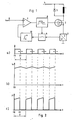
- FIG. 2a shows the course of the output voltage of the pulse width modulator, the time shift of the trailing edge dependent on the output voltage of the controller being indicated by a double arrow.
- the transistor 2 is conductive during the period t0 to t1. During the remaining part of the period T, the transistor 2 is blocked.
- the current is shown in FIG. 2b) through the coil 1 increases during the time t0 to t1 and then drops again until the transistor 2 is switched on again.
- a current i1 flows through the transistor 2 during the period t0 to t1.
- the current i2 flows through the free-wheeling diode 5 during the period t1 until the end of the period T.
- 2c) shows the time profile of the current i1 through the transistor, which can be detected with the aid of the current / voltage converter 3.
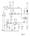
- the pulse width modulator is formed by a differential amplifier 12, one input 13 of which is a sawtooth-shaped signal and the other input of which is the output voltage of the regulator 7.
- the output of the differential amplifier 12 is connected via a resistor 14 to + UB and via a further resistor 15 to the control electrode of the transistor 2.
- the voltage UB is stabilized and is, for example, + 5V.
- OTA Operational Transductance Amplifier
- the OTA 17 is controlled via a transistor 26, the emitter of which is connected to the output of the differential amplifier 12 and the collector of which is connected to the control input 28 of the OTA 17 via a resistor 27.
- the transistor 26 is in turn controlled in that the voltage at the connection point 29 between the coil 1 and the transistor 2 is supplied to the base of the transistor 26 via a voltage divider 30, 31.
- a diode 32 is provided, which protects the base of transistor 26 from overvoltages.
- the illustrated control of the OTA 17 has the effect that the OTA 17 only delivers an output current when the transistor 2 and thus also the transistor 26 are conductive.
- the integrator is active during this time. During the remaining part of the period of the output signals of the pulse width modulator, the output of the OTA 17 is blocked, so that the output voltage of the integrator does not change.
Abstract
Bei einer Schaltungsanordnung zur Regelung eines pulsierenden Stroms durch eine Induktivität, insbesondere die Spule eines elektro-magnetischen Ventils, wobei die Induktivität in Reihe mit einem Halbleiterschalter und parallel zu einer Freilaufdiode geschaltet ist und wobei ferner eine Sollwertspannung einem Regler zuführbar ist, dessen Ausgang über einen Pulsbreitenmodulator mit einem Steuereingang des Halbleiterschalters verbunden ist, wird der bei leitendem Halbleiterschalter meßbare Strom zeitlich gewichtet und aufintegriert.In a circuit arrangement for regulating a pulsating current through an inductor, in particular the coil of an electro-magnetic valve, the inductor being connected in series with a semiconductor switch and in parallel with a freewheeling diode, and furthermore a setpoint voltage can be fed to a controller, the output of which is via a Pulse width modulator is connected to a control input of the semiconductor switch, the current which can be measured when the semiconductor switch is conductive is time-weighted and integrated.
Description
Die Erfindung betrifft eine Schaltungsanordnung zur Regelung eines pulsierenden Stroms durch eine Induktivität, insbesondere die Spule eines elektro-magnetischen Ventils, wobei die Induktivität in Reihe mit einem Halbleiterschalter und parallel zur einer Freilaufdiode geschaltet ist und wobei ferner eine Sollwertspannung einem Regler zuführbar ist, dessen Ausgang über einen Pulsbreitenmodulator mit einem Steuereingang des Halbleiterschalters verbunden ist.The invention relates to a circuit arrangement for regulating a pulsating current through an inductor, in particular the coil of an electro-magnetic valve, the inductor being connected in series with a semiconductor switch and in parallel with a free-wheeling diode, and furthermore a setpoint voltage can be fed to a controller whose output is connected to a control input of the semiconductor switch via a pulse width modulator.
Zur Regelung eines pulsierenden Stroms durch eine Induktivität ist eine möglichst genaue Erfassung des Stroms erforderlich. Bei den bekannten Schaltungen fließt in einem ersten Teil der Periodendauer ein Strom durch den Halbleiterschalter und die Induktivität. In einem zweiten Teil der Periodendauer ist der Halbleiterschalter nichtleitend. Die in der Induktivität gespeicherte magnetische Energie bewirkt jedoch einen weiteren Stromfluß durch den sogenannten Freilaufkreis, der aus der Induktivität und der parallelgeschalteten Freilaufdiode besteht. Eine genaue Messung des gesamten Stroms kann an sich nur in den Zuleitungen der Induktivität erfolgen, was jedoch aus schaltungstechnischen Gründen oft nicht möglich ist.In order to regulate a pulsating current through an inductance, the most accurate detection of the current is necessary. In the known circuits, a current flows through the semiconductor switch and the inductor in a first part of the period. In a second part of the period, the semiconductor switch is not conductive. However, the magnetic energy stored in the inductor causes a further current flow through the so-called Free-wheeling circuit, which consists of the inductance and the parallel-connected free-wheeling diode. A precise measurement of the total current can only be done in the inductor feed lines, which is often not possible for circuitry reasons.
Aufgabe der vorliegenden Erfindung ist es, eine Schaltungsanordnung zur Regelung eines pulsierenden Stroms durch eine Induktivität anzugeben, bei welcher aus einem zeitlichen Teil des Stromflusses, nämlich der Zeit, in der der Strom durch den Halbleiterschalter fließt, auf den Spulenstrom während der gesamten Periodendauer geschlossen werden kann.The object of the present invention is to provide a circuit arrangement for regulating a pulsating current through an inductor, in which the coil current is inferred from the temporal part of the current flow, namely the time in which the current flows through the semiconductor switch, during the entire period can.
Die erfindungsgemäße Schaltungsanordnung ist dadurch gekennzeichnet, daß der bei leitendem Halbleiterschalter meßbare Strom zeitlich gewichtet und aufintegriert wird.The circuit arrangement according to the invention is characterized in that the current which can be measured when the semiconductor switch is conducting is time-weighted and integrated.
Eine Weiterbildung der Erfindung besteht darin, daß eine Istwertspannung mit Hilfe eines Strom/Spannungswandlers, der in Reihe mit der Induktivität und dem Halbleiterschalter geschaltet ist, eines weiteren Schalters, der von dem Pulsbreitenmodulator steuerbar ist, und eines Integrators ableitbar ist.A further development of the invention consists in that an actual value voltage can be derived with the aid of a current / voltage converter which is connected in series with the inductance and the semiconductor switch, a further switch which can be controlled by the pulse width modulator and an integrator.
Durch die in den weiteren Unteransprüchen aufgeführten Maßnahmen sind weitere vorteilhafte Weiterbildungen und Verbesserungen der im Hauptanspruch angegebenen Erfindung möglich.The measures listed in the further subclaims further advantageous developments and improvements of the invention specified in the main claim are possible.
Die Erfindung läßt zahlreiche Ausführungsformen zu. Zwei davon sind schematisch in der Zeichnung anhand mehrerer Figuren dargestellt und nachfolgend beschrieben. Es zeigt:
- Fig. 1 ein Blockschaltbild einer ersten Ausführungsform,
- Fig. 2 Zeitdiagramme von bei der erfindungsgemäßen Schaltungsanordnung auftretenden Spannungen und Strömen und
- Fig. 3 ein Schaltbild einer zweiten Ausführungsform.
- 1 is a block diagram of a first embodiment;
- Fig. 2 timing diagrams of voltages and currents occurring in the circuit arrangement according to the invention and
- Fig. 3 is a circuit diagram of a second embodiment.
Gleiche Teile sind in den Figuren mit gleichen Bezugszeichen versehen.Identical parts are provided with the same reference symbols in the figures.
Bei der Schaltungsanordnung nach Fig. 1 ist eine Spule 1 in Reihe mit einem Transistor 2 und einem Strom/Spannungswandler 3 zwischen den positiven Pol 4 einer im einzelnen nicht dargestellten Betriebsspannungsquelle und Massepotential geschaltet. Die Spule 1 ist bei einem bevorzugten Anwendungsgebiet der erfindungsgemäßen Schaltung Teil eines elektromagnetischen Ventils, insbesondere eines Ventils zur Kraftstoffeinspritzung bei einem Verbrennungsmotor. In an sich bekannter Weise ist der Spule 1 eine Freilaufdiode 5 parallelgeschaltet.In the circuit arrangement according to FIG. 1, a
Über einen Eingang 6 wird einem Regler 7 als Sollwert eine Spannung Usoll zugeführt. Der Ausgang des Reglers 7 ist mit dem Eingang eines Pulsbreitenmodulators 8 verbunden, dessen Ausgang an die Steuerelektrode des Transistors 2 angeschlossen ist. Außerdem steuert der Pulsbreitenmodulator 8 einen Schalter 9, der beispielsweise von einem Feldeffekttransistor gebildet werden kann.A voltage Usoll is supplied as a setpoint to a
Der Strom/Spannungswandler 3 besteht im einfachsten Fall aus einem Widerstand, an welchem eine dem Strom proportionale Spannung abfällt. Diese wird über den Schalter 9 einem Integrator 10 zugeführt, dessen Ausgang mit dem invertierenden Eingang des Reglers 7 verbunden ist. Als Integrator 10 eignen sich verschiedene bekannte Schaltungen, beispielsweise ein sogenannter Miller-Integrator. Die Integrationszeitkonstante ist wesentlich größer als die Periodendauer des vom Pulsbreitenmodulator abgegebenen Signals. Der Regler 7 ist der Einfachheit halber als Differenzverstärker dargestellt. Es sind jedoch verschiedene Regler-Typen wie PI-Regler im Rahmen der Erfindung anwendbar.In the simplest case, the current / voltage converter 3 consists of a resistor, across which a voltage proportional to the current drops. This is fed via
Fig. 2a) zeigt den Verlauf der Ausgangsspannung des Pulsbreitenmodulators, wobei mit einem Doppelpfeil die von der Ausgangsspannung des Reglers abhängige zeitliche Verschiebung der Rückflanke angedeutet ist. Während des Zeitraums t0 bis t1 ist der Transistor 2 leitend. Während des restlichen Teils der Periodendauer T ist der Transistor 2 gesperrt. Entsprechend steigt der in Fig. 2b) dargestellte Strom is durch die Spule 1 während der Zeit t0 bis t1 an und fällt dann bis zum erneuten Einschalten des Transistors 2 wieder ab. Während des Zeitraums t0 bis t1 fließt also ein Strom i1 durch den Transistor 2. Der Strom i2 fließt während des Zeitraums t1 bis zum Ende der Periode T durch die Freilaufdiode 5. Fig. 2c) stellte den Zeitverlauf des Stroms i1 durch den Transistor dar, der mit Hilfe des Strom/Spannungswandlers 3 erfaßbar ist.2a) shows the course of the output voltage of the pulse width modulator, the time shift of the trailing edge dependent on the output voltage of the controller being indicated by a double arrow. The
Die Schaltungsanordnung nach Fig. 3 umfaßt ebenfalls eine Spule 1 und eine Freilaufdiode 5, die an den positiven Pol 4 einer Betriebsspannungsquelle angeschlossen sind. In Reihe dazu ist ebenfalls ein Transistor 2 geschaltet, der über einen Strommeßwiderstand 11 mit Massepotential verbunden ist. Ferner ist ebenfalls ein Regler 7 vorgesehen, dem über einen Eingang 6 die Spannung Usoll zugeführt wird. Der Pulsbreitenmodulator wird bei der Schaltungsanordnung nach Fig. 3 von einem Differenzverstärker 12 gebildet, dessen einem Eingang 13 ein sägezahnförmiges Signal und dessen anderem Eingang die Ausgangsspannung des Reglers 7 zugeleitet wird. Der Ausgang des Differenzverstärkers 12 ist über einen Widerstand 14 mit +UB und über einen weiteren Widerstand 15 mit der Steuerelektrode des Transistors 2 verbunden. Wie bei derartigen Schaltungsanordnungen üblich, ist die Spannung UB stabilisiert und beträgt beispielsweise +5V.3 also comprises a
Der dem Strom proportionale Spannungsabfall am Widerstand 11 wird über einen Widerstand 16 dem nichtinvertierenden Eingang eines schaltbaren Operationsverstärker (OTA = Operational Transductance Amplifier) 17 zugeführt, der als Betriebsspannung einerseits über einen Anschluß 18 die positive Spannung UB und andererseits über einen Anschluß 19 eine mit einem Kondensator 20 gesiebte negative Hilfsspannung UH von beispielsweise -3V erhält. An den Ausgang des OTA 17 sind ein Integrationskondensator 21 und ein zusammen mit einem Widerstand 22 als Emitterfolge geschalteter Transistor 23 angeschlossen. Vom Emitter des Transistors 23 wird die Ausgangsspannung des Integrators über einen Spannungsteiler 24, 25 auf den invertierenden Eingang des OTA 17 rückgekoppelt. Außerdem gelangt die Ausgangsspannung des Integrators zum invertierenden Eingang des Reglers 7.The voltage drop across the resistor 11, which is proportional to the current, is fed via a
Die Steuerung des OTA 17 erfolgt über einen Transistor 26, dessen Emitter mit dem Ausgang des Differenzverstärkers 12 und dessen Kollektor über einen Widerstand 27 mit dem Steuereingang 28 des OTA 17 verbunden ist. Die Steuerung des Transistors 26 wiederum erfolgt dadurch, daß die Spannung am Verbindungspunkt 29 zwischen der Spule 1 und dem Transistor 2 über einen Spannungsteiler 30, 31 der Basis des Transistors 26 zugeführt wird. Außerdem ist eine Diode 32 vorgesehen, welche die Basis des Transistors 26 vor Überspannungen schützt.The
Die dargestellte Steuerung des OTA 17 bewirkt, daß der OTA 17 nur einen Ausgangsstrom liefert, wenn der Transistor 2 und damit auch der Transistor 26 leitend sind. Während dieser Zeit ist der Integrator wirksam. Während des übrigen Teils der Periodendauer der Ausgangssignale des Pulsbreitenmodulators ist der Ausgang des OTA 17 gesperrt, so daß sich die Ausgangsspannung des Integrators nicht ändert.The illustrated control of the
Claims (5)
Applications Claiming Priority (2)
| Application Number | Priority Date | Filing Date | Title |
|---|---|---|---|
| DE19883824526 DE3824526A1 (en) | 1988-07-20 | 1988-07-20 | CIRCUIT ARRANGEMENT FOR CONTROLLING A PULSATING CURRENT |
| DE3824526 | 1988-07-20 |
Publications (2)
| Publication Number | Publication Date |
|---|---|
| EP0351451A2 true EP0351451A2 (en) | 1990-01-24 |
| EP0351451A3 EP0351451A3 (en) | 1990-11-22 |
Family
ID=6359070
Family Applications (1)
| Application Number | Title | Priority Date | Filing Date |
|---|---|---|---|
| EP19880118381 Withdrawn EP0351451A3 (en) | 1988-07-20 | 1988-11-04 | Control circuitry for a pulsating current |
Country Status (3)
| Country | Link |
|---|---|
| US (1) | US4978865A (en) |
| EP (1) | EP0351451A3 (en) |
| DE (1) | DE3824526A1 (en) |
Cited By (4)
| Publication number | Priority date | Publication date | Assignee | Title |
|---|---|---|---|---|
| DE4117535A1 (en) * | 1991-05-29 | 1992-12-03 | Miele & Cie | Relay control circuit for domestic electrical appliance - uses switching transistor supplied with control signal dependent on supply voltage amplitude |
| DE9409760U1 (en) * | 1993-06-25 | 1994-09-01 | Siemens Ag | Circuit arrangement for controlling a contactor |
| DE9409759U1 (en) * | 1993-06-25 | 1994-10-27 | Siemens Ag | Circuit arrangement for realizing a constant contactor holding current |
| WO1998013847A1 (en) * | 1996-09-24 | 1998-04-02 | Siemens Aktiengesellschaft | Circuit arrangement to provide an electromagnetically operated mechanism of a switchgear with an electricity supply |
Families Citing this family (39)
| Publication number | Priority date | Publication date | Assignee | Title |
|---|---|---|---|---|
| DE3805031C2 (en) * | 1988-02-18 | 1997-04-17 | Bosch Gmbh Robert | Device for controlling an electromagnetic consumer |
| JPH03164912A (en) * | 1989-11-24 | 1991-07-16 | Mitsubishi Electric Corp | Driving device for duty solenoid valve |
| DE4011217A1 (en) * | 1990-04-06 | 1991-10-10 | Lucas Ind Plc | Controlling magnetic-valve in antilocking braking system - ascertaining function of valve by tapping voltage of transistor setting current flow through solenoid |
| DE4026427C1 (en) * | 1990-08-21 | 1992-02-13 | Siemens Ag, 8000 Muenchen, De | |
| JP3030076B2 (en) * | 1990-11-01 | 2000-04-10 | 三菱電機株式会社 | Current control circuit |
| US5087866A (en) * | 1991-05-22 | 1992-02-11 | Lucas Industries | Temperature compensating circuit for LVDT and control system |
| US5255152A (en) * | 1991-08-21 | 1993-10-19 | Eaton Corporation | Controller for fixed-time pull-in of a relay |
| US5543632A (en) * | 1991-10-24 | 1996-08-06 | International Business Machines Corporation | Temperature monitoring pilot transistor |
| US5245261A (en) * | 1991-10-24 | 1993-09-14 | International Business Machines Corporation | Temperature compensated overcurrent and undercurrent detector |
| US5237262A (en) * | 1991-10-24 | 1993-08-17 | International Business Machines Corporation | Temperature compensated circuit for controlling load current |
| DE4201652C2 (en) * | 1992-01-22 | 1997-11-06 | Rexroth Mannesmann Gmbh | Proportional valve with control circuit and mains voltage operation |
| US5450270A (en) * | 1992-12-09 | 1995-09-12 | Jatco Corporation | Solenoid valve control system |
| TW241370B (en) * | 1992-12-15 | 1995-02-21 | Fuji Electrical Machinery Co Ltd | |
| DE4341797A1 (en) * | 1993-12-08 | 1995-06-14 | Bosch Gmbh Robert | Method and device for controlling an electromagnetic consumer |
| JP3134724B2 (en) * | 1995-02-15 | 2001-02-13 | トヨタ自動車株式会社 | Valve drive for internal combustion engine |
| FR2734394A1 (en) * | 1995-05-17 | 1996-11-22 | Caterpillar Inc | Control circuit for electromagnetic actuator |
| US5621603A (en) * | 1995-07-26 | 1997-04-15 | United Technologies Corporation | Pulse width modulated solenoid driver controller |
| DE19623442A1 (en) * | 1996-06-12 | 1998-01-02 | Telefunken Microelectron | Device for determining the current flowing in an inductor |
| WO1998024008A1 (en) * | 1996-11-22 | 1998-06-04 | Temic Telefunken Microelectronic Gmbh | Control circuit with a digital controller regulating the input current of an electronic actuator by means of pulse width modulation |
| US5815362A (en) * | 1996-12-04 | 1998-09-29 | Westinghouse Air Brake Company | Pulse width modulated drive for an infinitely variable solenoid operated brake cylinder pressure control valve |
| DE19706247B4 (en) * | 1997-02-18 | 2005-05-19 | Burgert, Markus | Circuit arrangement for controlling electromagnets and regulating the coil current |
| US6208497B1 (en) | 1997-06-26 | 2001-03-27 | Venture Scientifics, Llc | System and method for servo control of nonlinear electromagnetic actuators |
| US6942469B2 (en) | 1997-06-26 | 2005-09-13 | Crystal Investments, Inc. | Solenoid cassette pump with servo controlled volume detection |
| DE29715925U1 (en) * | 1997-09-05 | 1997-10-23 | Festo Ag & Co | Circuit device |
| US5818678A (en) * | 1997-10-09 | 1998-10-06 | Delco Electronics Corporation | Tri-state control apparatus for a solenoid having on off and PWM control modes |
| DE19756461A1 (en) * | 1997-12-18 | 1999-07-01 | Bosch Gmbh Robert | Method for influencing the electrical power of a load with a pulse width modulated signal |
| US6982323B1 (en) * | 1997-12-23 | 2006-01-03 | Alexion Pharmaceuticals, Inc. | Chimeric proteins for diagnosis and treatment of diabetes |
| JP4118414B2 (en) * | 1998-10-29 | 2008-07-16 | サンデン株式会社 | Control circuit for capacity control valve of variable capacity compressor |
| DE19915593A1 (en) * | 1999-04-07 | 2000-11-16 | Daimler Chrysler Ag | Circuit arrangement for determination of the average current through an inductive component especially for use in automotive applications, such as actuators or control valves, has a parallel connected low pass filter |
| US6493204B1 (en) | 1999-07-09 | 2002-12-10 | Kelsey-Hayes Company | Modulated voltage for a solenoid valve |
| US7315440B1 (en) | 2003-12-09 | 2008-01-01 | Yazaki North America, Inc. | Circuit and method for driving a coil-armature device |
| DE10358858A1 (en) * | 2003-12-16 | 2005-07-14 | Robert Bosch Gmbh | Method and device for operating an inductive load with different electrical voltages |
| FR2899718B1 (en) * | 2006-04-11 | 2008-05-23 | Crouzet Automatismes Soc Par A | ELECTRIC ARC DETECTION DEVICE, CUTTING DEVICE COMPRISING SUCH A DEVICE AND METHOD FOR DETECTING ELECTRIC ARC |
| DE102006058879A1 (en) * | 2006-12-13 | 2008-06-26 | Siemens Ag | Measuring device for measuring an electric current |
| DE102008055696A1 (en) | 2008-01-25 | 2009-07-30 | Continental Teves Ag & Co. Ohg | Electronic circuit device for detecting a detection element current and / or a temperature in this detection element |
| GB2470211B (en) * | 2009-05-14 | 2013-07-31 | Gm Global Tech Operations Inc | Hysteresis-type electronic controlling device for fuel injectors and associated method |
| US8786138B2 (en) * | 2010-05-21 | 2014-07-22 | General Electric Company | Systems, methods, and apparatus for controlling actuator drive current using bi-directional hysteresis control |
| FR2971102B1 (en) * | 2011-02-01 | 2019-09-06 | Safran Landing Systems | METHOD FOR LIMITING A CURRENT PROVIDED BY A DIRECT CURRENT POWER SOURCE. |
| CN102426984B (en) * | 2011-11-29 | 2013-12-04 | 福州大学 | High-frequency control system for electricity interference resisting intelligent alternating current contactor |
Citations (4)
| Publication number | Priority date | Publication date | Assignee | Title |
|---|---|---|---|---|
| EP0074536A2 (en) * | 1981-09-10 | 1983-03-23 | Robert Bosch Gmbh | Electric commutation apparatus for a control device for a motor-driven vehicle |
| EP0203354A1 (en) * | 1985-04-25 | 1986-12-03 | Audi Ag | Process and circuit for the control of a valve |
| US4661766A (en) * | 1985-12-23 | 1987-04-28 | Caterpillar Inc. | Dual current sensing driver circuit |
| EP0252638A1 (en) * | 1986-07-11 | 1988-01-13 | LUCAS INDUSTRIES public limited company | Drive circuit |
Family Cites Families (5)
| Publication number | Priority date | Publication date | Assignee | Title |
|---|---|---|---|---|
| JPS56151261A (en) * | 1980-04-24 | 1981-11-24 | Japan Electronic Control Syst Co Ltd | Operating device for fuel injection valve |
| JPS57121703A (en) * | 1981-01-22 | 1982-07-29 | Nippon Denso Co Ltd | Driving circuit of electromagnetic operating device |
| JPS5851233A (en) * | 1981-09-21 | 1983-03-25 | Hitachi Ltd | Fuel injection valve driving circuit |
| US4556926A (en) * | 1982-09-27 | 1985-12-03 | Ricoh Company, Ltd. | Electromagnet driving circuit |
| ES8703213A1 (en) * | 1985-04-25 | 1987-02-16 | Kloeckner Wolfgang Dr | Control process and system for an electromagnetic engine valve. |
-
1988
- 1988-07-20 DE DE19883824526 patent/DE3824526A1/en not_active Withdrawn
- 1988-11-04 EP EP19880118381 patent/EP0351451A3/en not_active Withdrawn
-
1989
- 1989-04-20 US US07/341,147 patent/US4978865A/en not_active Expired - Fee Related
Patent Citations (4)
| Publication number | Priority date | Publication date | Assignee | Title |
|---|---|---|---|---|
| EP0074536A2 (en) * | 1981-09-10 | 1983-03-23 | Robert Bosch Gmbh | Electric commutation apparatus for a control device for a motor-driven vehicle |
| EP0203354A1 (en) * | 1985-04-25 | 1986-12-03 | Audi Ag | Process and circuit for the control of a valve |
| US4661766A (en) * | 1985-12-23 | 1987-04-28 | Caterpillar Inc. | Dual current sensing driver circuit |
| EP0252638A1 (en) * | 1986-07-11 | 1988-01-13 | LUCAS INDUSTRIES public limited company | Drive circuit |
Cited By (4)
| Publication number | Priority date | Publication date | Assignee | Title |
|---|---|---|---|---|
| DE4117535A1 (en) * | 1991-05-29 | 1992-12-03 | Miele & Cie | Relay control circuit for domestic electrical appliance - uses switching transistor supplied with control signal dependent on supply voltage amplitude |
| DE9409760U1 (en) * | 1993-06-25 | 1994-09-01 | Siemens Ag | Circuit arrangement for controlling a contactor |
| DE9409759U1 (en) * | 1993-06-25 | 1994-10-27 | Siemens Ag | Circuit arrangement for realizing a constant contactor holding current |
| WO1998013847A1 (en) * | 1996-09-24 | 1998-04-02 | Siemens Aktiengesellschaft | Circuit arrangement to provide an electromagnetically operated mechanism of a switchgear with an electricity supply |
Also Published As
| Publication number | Publication date |
|---|---|
| US4978865A (en) | 1990-12-18 |
| EP0351451A3 (en) | 1990-11-22 |
| DE3824526A1 (en) | 1990-01-25 |
Similar Documents
| Publication | Publication Date | Title |
|---|---|---|
| EP0351451A2 (en) | Control circuitry for a pulsating current | |
| DE3708892C2 (en) | Current measuring device, in particular for determining the motor current of a DC motor | |
| DE2122472C3 (en) | Wide-angle display device for displaying signal voltages | |
| DE1283891B (en) | Electronic circuit arrangement for switching a useful signal transmission on and off | |
| DE3507103A1 (en) | DRIVER CIRCUIT FOR A MAGNETIC COIL | |
| DE2745294A1 (en) | THRESHOLD CIRCUIT FOR AN ELECTRONIC IGNITION SYSTEM | |
| DE2940018A1 (en) | INDUCTIVE MEASURING DEVICE, IN PARTICULAR FOR AN INTERNAL COMBUSTION ENGINE | |
| DE3219815C2 (en) | ||
| DE2061943C3 (en) | Differential amplifier | |
| DE3626088C2 (en) | ||
| EP0280261A2 (en) | Circuit for getting a temperature independent rectangular signal from a measuring signal | |
| DE3710871A1 (en) | CIRCUIT FOR SHAPING A MEASURING SIGNAL VOLTAGE IN A RECTANGULAR SIGNAL | |
| EP0944159A2 (en) | DC-DC converter | |
| DE1142902B (en) | Pulse width modulator with two transistors | |
| DE3212942C2 (en) | ||
| EP0432280A1 (en) | Interface between two electrical circuits operating under different supply voltages | |
| DE4336726A1 (en) | Circuit for current measurement | |
| DE3405599A1 (en) | Current sensor for the control loop of a switched-mode regulator | |
| DE3303945A1 (en) | Temperature-compensating circuit for a Hall generator power supply | |
| DE3210890C2 (en) | ||
| DE3034023C2 (en) | ||
| DE102022101876B4 (en) | Magnetic core for current sensors | |
| DE3813066A1 (en) | Switched current regulator | |
| EP0217147A1 (en) | Circuit arrangement for feeding signals to a rotating magnet measuring unit | |
| DE2100929A1 (en) | Control circuit for supplying an inductive consumer |
Legal Events
| Date | Code | Title | Description |
|---|---|---|---|
| PUAI | Public reference made under article 153(3) epc to a published international application that has entered the european phase |
Free format text: ORIGINAL CODE: 0009012 |
|
| AK | Designated contracting states |
Kind code of ref document: A2 Designated state(s): DE FR GB IT |
|
| PUAL | Search report despatched |
Free format text: ORIGINAL CODE: 0009013 |
|
| AK | Designated contracting states |
Kind code of ref document: A3 Designated state(s): DE FR GB IT |
|
| STAA | Information on the status of an ep patent application or granted ep patent |
Free format text: STATUS: THE APPLICATION IS DEEMED TO BE WITHDRAWN |
|
| 18D | Application deemed to be withdrawn |
Effective date: 19910514 |