EP0350649A2 - Cross-country ski binding - Google Patents
Cross-country ski binding Download PDFInfo
- Publication number
- EP0350649A2 EP0350649A2 EP89110943A EP89110943A EP0350649A2 EP 0350649 A2 EP0350649 A2 EP 0350649A2 EP 89110943 A EP89110943 A EP 89110943A EP 89110943 A EP89110943 A EP 89110943A EP 0350649 A2 EP0350649 A2 EP 0350649A2
- Authority
- EP
- European Patent Office
- Prior art keywords
- ski
- base plate
- cross
- holding shell
- ski boot
- Prior art date
- Legal status (The legal status is an assumption and is not a legal conclusion. Google has not performed a legal analysis and makes no representation as to the accuracy of the status listed.)
- Granted
Links
Images

Classifications
-
- A—HUMAN NECESSITIES
- A63—SPORTS; GAMES; AMUSEMENTS
- A63C—SKATES; SKIS; ROLLER SKATES; DESIGN OR LAYOUT OF COURTS, RINKS OR THE LIKE
- A63C9/00—Ski bindings
- A63C9/20—Non-self-releasing bindings with special sole edge holders instead of toe-straps
Abstract
Description
Die Erfindung betrifft eine Skibindung für einen Langlauf- oder Tourenski gemäß dem Oberbegriff des Anspruches 1.The invention relates to a ski binding for a cross-country or touring ski according to the preamble of
Eine solche Skibindung ist in der WO 87/03211 beschrieben. Bei dieser bekannten Skibindung ist eine Halteschale zur Aufnahme des vorderen Bereiches eines Langlaufskischuhes vorgesehen. Dabei weist die Halteschale eine Bodenplatte mit einer Aussparung für einen Verriegelungszapfen und, in einem Abstand darüber, Halteleisten auf, wobei Bodenplatte und Halteleisten nach vorne zu konvergierend ausgebildet sind. Der zugehörige Langlaufskischuh trägt an seinem vorderen Endbreich einen U-förmigen Haltebügel, welcher mit der Schuhsohle eine Öffnung bildet. In diese Öffnung ragt in der Schließstellung der Skibindung der Verriegelungszapfen. Der vordere Sohlenbereich des Langlaufskischuhes ist mit oberen und unteren Führungsflächen versehen, welche Führungsflächen so ausgestaltet sind, daß sie sich bei eingesetztem Skischuh an der Bodeplatte und an den Führungsleisten der Halteschale abstützen.Such a ski binding is described in WO 87/03211. In this known ski binding, a holding shell is provided for receiving the front area of a cross-country ski boot. The holding shell has a base plate with a recess for a locking pin and, at a distance above it, retaining strips, the base plate and retaining strips being designed to converge towards the front. The associated cross-country ski boot has a U-shaped bracket on its front end area, which forms an opening with the sole of the boot. The locking pin protrudes into this opening in the closed position of the ski binding. The front sole area of the cross-country ski shoe is provided with upper and lower guide surfaces, which guide surfaces are designed such that they are supported on the base plate and on the guide strips of the holding shell when the ski shoe is inserted.
Eine derartige Langlaufskibindung mit dem dazu passenden Langlaufskischuh ist auch im Handel erhältlich und hat sich in der Praxis bewährt. Dabei hat sich aber herausgestellt, daß sich die Sohle des Langlaufskischuhes vor allem an ihrem vorderen Ende durch das Gehen auch auf gestreuten Wegen abnützt. Dadurch verändert sich die Geometrie der Führungsflächen ungünstig, wodurch die gleichmäßige Abstützung des Skischuhes in der Halteschale nicht mehr gewährleistet ist.Such a cross-country ski binding with the matching cross-country ski boot is also commercially available and has proven itself in practice. It has been found, however, that the sole of the cross-country ski boot wears down, especially at its front end, by walking on strewn paths. As a result, the geometry of the guide surfaces changes unfavorably, as a result of which the uniform support of the ski boot in the holding shell is no longer guaranteed.
Die Erfindung hat sich die Aufgabe gestellt, bei einer Skibindung der eingangs genannten Art die Halteschale so auszugestalten, daß sich abnützungsbedingte Veränderungen der Laufsohle des Langlaufskischuhes nicht mehr auf die Abstützung desselben in der Halteschale auswirken.The invention has set itself the task of designing the holding shell in a ski binding of the type mentioned in such a way that wear-related changes in the outsole of the cross-country ski boot no longer have an effect on the support thereof in the holding shell.
Erreicht wird das gesetzte Ziel erfindungsgemäß durch die kennzeichnenden Merkmale des Anspruches 1. Dadurch, daß die Bodenplatte der Halteschale mit zumindest einem erhöhten Bereich versehen ist, an welchem der eingesetzte Skischuh mit seinem Bügel bzw. Quersteg aufliegt, ist die Abstützung des Langlaufskischuhes in der Halteschale unabhängig von einer möglichen Laufsohlenabnützung sicher gewährleistet.The set goal is achieved according to the invention by the characterizing features of
Die Maßnahme, an einem der Halterung des Skischuhes dienenden Bauteil einer Langlaufskibindung einen erhöhten Bereich für den Haltebügel des Skischuhes vorzusehen, ist an sich aus der DE-OS 34 01 080 bekannt. Diese bekannte Langlaufskibindung besitzt allerdings keine Halteschale und ist daher vom Erfindungsgegenstand weiter entfernt als der oben erwähnte Stand der Technik.The measure of providing a raised area for the retaining bracket of the ski shoe on a component of a cross-country ski binding used to hold the ski shoe is known per se from DE-OS 34 01 080. However, this known cross-country ski binding has no holding shell and is therefore further from the subject matter of the invention than the prior art mentioned above.
Durch die Maßnahmen der kennzeichnenden Merkmale des Anspruches 2 ist eine besonders vorteilhafte Ausgestaltung der erhöhten Bereiche bei gleichzeitiger kompakter Gestaltung der Halteschale gegeben.The measures of the characterizing features of
Die Merkmale des Anspruches 3 bewirken, daß der Quersteg des Langlaufskischuhes gegen ein unbeabsichtigtes Herausgleiten nach hinten besonders gesichert ist.The features of
Durch die Ausgestaltung nach den Merkmalen des Anspruches 4 wird ein fertigungsgünstiger Aufbau der Halteschale und insbesondere deren leichtere Entformbarkeit gewährleistet.The configuration according to the features of
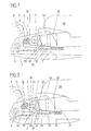
Weitere Vorteile, Merkmale und Einzelheiten der Erfindung werden nun anhand der Zeichnung näher beschrieben. Hiebei zeigen: Fig.1 Teile der den Stand der Technik bildenden Langlaufskibindung im Längsschnitt und mit eingesetztem Langlaufskischuh, Fig.2 eine entsprechende Darstellung einer Langlaufskibindung mit der erfindungsgemäß ausgestalteten Halteschale, Fig.3 die Halteschale in der Draufsicht, teilweise aufgerissen, Fig.4 eine zweite Ausführungsform der erfindungsgemäßen Langlaufskibindung im Längsschnitt und Fig.5 einen Schnitt nach der Linie V-V der Fig.4.Further advantages, features and details of the invention will now be described with reference to the drawing. 1 shows parts of the cross-country ski binding that forms the state of the art in longitudinal section and with a cross-country ski boot inserted, FIG. 2 shows a corresponding representation of a cross-country ski binding with the holding shell designed according to the invention, FIG. 3 shows the holding shell in a top view, partially broken open, FIG. 4 a second embodiment of the cross-country ski binding according to the invention in longitudinal section and Figure 5 shows a section along the line VV of Figure 4.
In Fig.1 ist schematisch und teilweise in Seitenansicht, teilweise im Schnitt eine Langlaufskibindung gemäß dem Stand der Technik dargestellt. Dabei wurden jene Teile der Langlaufskibindung, die nicht zur Halteschale und zu dem in die Bindung einsetzbaren vorderen Bereich des Langlaufskischuhes gehören, nur strichpunktiert dargestellt oder weggelassen.1 shows a cross-country ski binding according to the prior art, schematically and partly in side view, partly in section. Those parts of the cross-country ski binding that were not the holding shell and which were in the Binding insertable front area of the cross-country ski boot belong, shown only in dash-dotted lines or omitted.
Auf einem Ski 1 ist eine Grundplatte 2 einer Langlaufskibindung in beliebiger bekannter Weise montiert. Die Grundplatte 2 weist einen Lagerbock 3 auf, an welchem auf einer Querachse 4 eine nachfolgend noch genauer beschriebene Halteschale 5 schwenkbar gelagert ist. An der Querachse 4 ist weiters ein Schwenkteil 6 gelagert. Der Schwenkteil 6 trägt an seinem einen Arm einen Verriegelungszapfen 7 und an seinem anderen, nach oben gerichteten Arm eine weitere Querachse 8, an welcher ein als zweiarmiger Hebel ausgebildeter Riegel 9 angelenkt ist. Bezüglich der genauen Ausgestaltung und Funktion der Langlaufskibindung wird auf die WO 87/03211 verwiesen. Die an der Querachse 4 angelenkte Halteschale 5 weist im wesentlichen eine Bodenplatte 51 mit einer Aussparung 52 auf. An beiden Seiten der Bodenplatte 51, in Skilängsrichtung betrachtet, schließen jeweils Seitenwände 53 an. Die Seitenwände 53 sind an ihren oberen Enden mit nach innen, also zur Längsachse hin, gerichteten Halteleisten 54 versehen. Weiters weist die Halteschale 5 in ihrem der Querachse 4 zugewandten Bereich einen Quersteg 55 mit einer Rastnut 56 auf. In diese Rastnut 56 greift in der Schließstellung der Langlaufskibindung in bekannter Weise ein als Rastnase 10 ausgebildeter Hebelarm des Riegels 9 ein.A
In die Halteschale ist ein mit 20 bezeichneter Langlaufskischuh eingesetzt. Der Langlaufskischuh 20 hat eine Sohle 21, in deren vorderem Endbereich 22 in bekannter Weise ein U-förmig ausgebildeter Bügel 23 verankert ist. Dadurch entsteht zwischen dem Bügel 23 und der Sohle 21 eine Öffnung 24, in welche bei geschlossener Skibindung der Verriegelungszapfen 7 ragt. Von der Seite betrachtet weist der vordere Endbereich 22 der Sohle 21 keilförmig zulaufende obere und untere Führungsflächen 25 bzw. 26 auf, wobei die untere Führungsfläche 26 dazu bestimmt ist, auf der Bodenplatte 51 der Halteschale 5 aufzuliegen. Der Winkel zwischen der oberen 25 und unteren Führungsfläche 26 ist der gleiche wie der Winkel zwischen den Führungsleisten 54 und der Bodenplatte 51 der Halteschale, da bei in die Bindung eingesetztem Skischuh 20 die obere Führungsfläche 25 von unten an den Führungsleisten 54 der Halteschale 5 anliegen soll. Hinsichtlich der weiteren Ausgestaltung des Langlaufskischuhes 20 wird ebenfalls auf die WO 87/03211 verwiesen.A cross-country ski boot labeled 20 is inserted into the holding shell. The
In Fig.1 ist erkennbar, daß sich die untere Führungsfläche 26 nach längerem Gebrauch des Langlaufskischuhes 20 abnützt und nun nicht mehr an der Bodenplatte 51 anliegt. Diese Situation ist strichliert dargestellt und die abgenützte untere Führungsfläche mit 26′ bezeichnet. Durch diese Abnützung ist der Langlaufskischuh 20 in der Halteschale 5 nicht mehr sicher und spielfrei gehalten.In FIG. 1 it can be seen that the
Es werden nunmehr zwei bevorzugte Ausführungsformen der Erfindung beschrieben. In diesen Figuren sind Teile, welche mit denjenigen der Fig.1 identisch oder analog sind, mit den gleichen Bezugszeichen gekennzeichnet.Two preferred embodiments of the invention will now be described. In these figures, parts which are identical or analogous to those in FIG. 1 are identified by the same reference numerals.
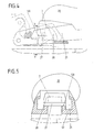
Wie in Fig.2 und in der zugehörigen Draufsicht nach Fig.3 erkennbar ist, weist die Bodenplatte 51 Seitenflächen 57 auf. Die Seitenflächen 57 sind in ihrem der Querachse 4 näher gelegenen Abschnitt mit relativ zur Bodenplatte 51 erhöhten Bereichen 58 versehen. Diese erhöhten Bereiche 58 können, wie in der Zeichnung dargestellt, annähernd parallel zur Bodenplatte 51 ausgebildet sein. Diese Ausführungsvariante ist besonders in Bezug auf die möglichst unkomplizierte Gestaltung der Spritzgu form und auf die leichte Entformbarkeit günstig. Es ist aber auch möglich, die erhöhten Bereiche 58 nach vorne zu geneigt auszubilden. Diese Lösung wird man dann wählen, wenn auf einen besonders sicheren Halt des Bügels 23 in der Skibindung Wert gelegt wird.As can be seen in FIG. 2 and in the associated top view according to FIG. 3, the
Wie in Fig.2 erkennbar ist, liegt der Bügel 23 des Langlaufskischuhes 20 auf den erhöhten Bereichen 58 der Bodenplatte 51 auf. Dadurch hat nun eine Abnützung der unteren Führungsfläche 26 bzw.26′ der Sohle 21 keine negative Auswirkung auf die Positionierung des Langlaufskischuhes 20 in der Halteschale mehr.As can be seen in FIG. 2, the
In den Fig.4 und 5 ist eine zweite Ausführungsform der erfindungsgemäßen Skibindung dargestellt.4 and 5 show a second embodiment of the ski binding according to the invention.
Dabei wurden ebenfalls für gleich oder analog gestaltete Teile gleiche Bezugsziffern verwendet. Bei dieser Ausführungsform weist der Langlaufskischuh 20 statt eines U-förmigen Bügels einen Quersteg 27 auf. Der Quersteg 27 ist ebenfalls in bekannter Weise in der Sohle 21 verankert, wodurch gleichfalls zwischen dem Quersteg 27 und der Sohle 21 eine Öffnung 28 entsteht. In diese Öffnung 28 greift, wie schon beschrieben, der Verriegelungszapfen 7 ein. Bei dieser Ausführungsform sind die erhöhten Bereiche 58 an dem Verriegelungszapfen 7 zugewandten Abschnitten der Seitenflächen 57 ausgebildet.The same reference numerals have also been used for identical or analog parts. In this embodiment, the
Die Erfindung ist auf die dargestellten Ausführungsbeispiele nicht eingeschränkt. Die Erfindung ist auch bei Skibindungen anwendbar, bei welchen die Verriegelung bzw. Verrastung der Halteschale und die Schließung bzw. Öffnung der Skibindung anders als bei der den Stand der Technik bildenden, in der WO 87/03211 beschriebenen Skibindung funktioniert. Auch die Form des Bereiches bzw. der erhöhten Bereiche kann beliebig gestaltet werden.The invention is not restricted to the exemplary embodiments shown. The invention can also be used for ski bindings in which the locking or latching of the holding shell and the closing or opening of the ski binding functions differently than in the ski binding described in WO 87/03211, which forms the prior art. The shape of the area or the raised areas can also be designed as desired.
Claims (4)
Applications Claiming Priority (2)
| Application Number | Priority Date | Filing Date | Title |
|---|---|---|---|
| AT1794/88 | 1988-07-12 | ||
| AT179488A AT390385B (en) | 1988-07-12 | 1988-07-12 | SKI BINDING FOR A CROSS-COUNTRY SKIING OR TOURING SKI |
Publications (3)
| Publication Number | Publication Date |
|---|---|
| EP0350649A2 true EP0350649A2 (en) | 1990-01-17 |
| EP0350649A3 EP0350649A3 (en) | 1990-09-26 |
| EP0350649B1 EP0350649B1 (en) | 1992-12-30 |
Family
ID=3521113
Family Applications (1)
| Application Number | Title | Priority Date | Filing Date |
|---|---|---|---|
| EP19890110943 Expired - Lifetime EP0350649B1 (en) | 1988-07-12 | 1989-06-16 | Cross-country ski binding |
Country Status (3)
| Country | Link |
|---|---|
| EP (1) | EP0350649B1 (en) |
| AT (1) | AT390385B (en) |
| DE (1) | DE58903150D1 (en) |
Families Citing this family (1)
| Publication number | Priority date | Publication date | Assignee | Title |
|---|---|---|---|---|
| AT398279B (en) * | 1990-03-30 | 1994-11-25 | Tyrolia Freizeitgeraete | SKI BINDING FOR A CROSS-COUNTRY SKIING OR TOURING SKI |
Citations (2)
| Publication number | Priority date | Publication date | Assignee | Title |
|---|---|---|---|---|
| EP0163054A1 (en) * | 1984-04-11 | 1985-12-04 | Matess di, Mario Tessaro | Combination of a binding and a foot wear |
| WO1987003211A1 (en) * | 1985-11-22 | 1987-06-04 | Tmc Corporation | Ski binding for cross-country or touring ski-ing |
Family Cites Families (1)
| Publication number | Priority date | Publication date | Assignee | Title |
|---|---|---|---|---|
| FR2540392B1 (en) * | 1983-02-09 | 1985-07-19 | Salomon & Fils F | DEVICE FOR ATTACHING A SHOE TO A CROSS-COUNTRY OR HIKING SKI |
-
1988
- 1988-07-12 AT AT179488A patent/AT390385B/en not_active IP Right Cessation
-
1989
- 1989-06-16 EP EP19890110943 patent/EP0350649B1/en not_active Expired - Lifetime
- 1989-06-16 DE DE8989110943T patent/DE58903150D1/en not_active Expired - Fee Related
Patent Citations (2)
| Publication number | Priority date | Publication date | Assignee | Title |
|---|---|---|---|---|
| EP0163054A1 (en) * | 1984-04-11 | 1985-12-04 | Matess di, Mario Tessaro | Combination of a binding and a foot wear |
| WO1987003211A1 (en) * | 1985-11-22 | 1987-06-04 | Tmc Corporation | Ski binding for cross-country or touring ski-ing |
Also Published As
| Publication number | Publication date |
|---|---|
| EP0350649A3 (en) | 1990-09-26 |
| EP0350649B1 (en) | 1992-12-30 |
| AT390385B (en) | 1990-04-25 |
| ATA179488A (en) | 1989-10-15 |
| DE58903150D1 (en) | 1993-02-11 |
Similar Documents
| Publication | Publication Date | Title |
|---|---|---|
| EP0551899B1 (en) | Cross-country or touring skibinding for cross-country ski shoes | |
| AT396068B (en) | SKI BINDING FOR A CROSS-COUNTRY SKIING OR TOURING SKI | |
| DE3151584A1 (en) | TOTAL BINDING OF A SHOE WITH A SKI, ESPECIALLY A CROSS-COUNTRY SKI | |
| DD238726A5 (en) | GUIDANCE APPARATUS OF A SHOE, AND SHOE AND SURFACE ADJUSTED TO THIS DEVICE | |
| WO1997047367A1 (en) | Cross-country or touring ski binding | |
| DE4428154C2 (en) | Arrangement of a cross-country ski binding and a cross-country ski boot adapted to it | |
| DD239338A5 (en) | SIDE GUIDE DEVICE OF AN SKI SHOE, AND TO THIS DEVICE ATTACHED SHOE AND CROSS-COAST SKI | |
| EP0120295A1 (en) | Maintaining device for removable locking elements on ski bindings | |
| DE3447012C2 (en) | Device comprising a safety ski binding fastened to a ski and a ski boot, as well as ski boots and ski binding | |
| DE3707116A1 (en) | ARRANGEMENT FOR FASTENING A SKI SHOE ON A CROSS-COUNTRY OR TOURING SKI | |
| EP0176952A1 (en) | Combination of a ski binding and a foot wear | |
| EP0830185B1 (en) | Arrangement for a cross-country ski binding, in particular a skating binding | |
| DE2807592A1 (en) | CROSS-COUNTRY SKI BINDING | |
| AT390385B (en) | SKI BINDING FOR A CROSS-COUNTRY SKIING OR TOURING SKI | |
| EP0272317B1 (en) | Safety ski binding | |
| DE3915946A1 (en) | CROSS-COUNTRY SKI BINDING | |
| AT398279B (en) | SKI BINDING FOR A CROSS-COUNTRY SKIING OR TOURING SKI | |
| AT399101B (en) | FRONT JAW | |
| EP0129535A1 (en) | Combination of cross-country ski binding and cross-country ski-boot | |
| DE3341258A1 (en) | SKI BRAKE AND METHOD FOR FASTENING IT | |
| EP0219717B1 (en) | Safety binding for touring | |
| AT386127B (en) | Ski binding for a cross-country or touring ski | |
| DE3539315C1 (en) | Touring safety binding | |
| DE2637871A1 (en) | Safety ski binding with sole holder - swivels sideways and includes housing swivelling around transverse axis | |
| EP0254829B1 (en) | Ski safety binding |
Legal Events
| Date | Code | Title | Description |
|---|---|---|---|
| PUAI | Public reference made under article 153(3) epc to a published international application that has entered the european phase |
Free format text: ORIGINAL CODE: 0009012 |
|
| AK | Designated contracting states |
Kind code of ref document: A2 Designated state(s): CH DE FR LI SE |
|
| PUAL | Search report despatched |
Free format text: ORIGINAL CODE: 0009013 |
|
| AK | Designated contracting states |
Kind code of ref document: A3 Designated state(s): CH DE FR LI SE |
|
| 17P | Request for examination filed |
Effective date: 19910316 |
|
| RAP1 | Party data changed (applicant data changed or rights of an application transferred) |
Owner name: TMC CORPORATION |
|
| 17Q | First examination report despatched |
Effective date: 19920429 |
|
| GRAA | (expected) grant |
Free format text: ORIGINAL CODE: 0009210 |
|
| RAP1 | Party data changed (applicant data changed or rights of an application transferred) |
Owner name: HTM SPORT- UND FREIZEITGERAETE GESELLSCHAFT M.B.H. |
|
| AK | Designated contracting states |
Kind code of ref document: B1 Designated state(s): CH DE FR LI SE |
|
| REF | Corresponds to: |
Ref document number: 58903150 Country of ref document: DE Date of ref document: 19930211 |
|
| ET | Fr: translation filed | ||
| PLBE | No opposition filed within time limit |
Free format text: ORIGINAL CODE: 0009261 |
|
| STAA | Information on the status of an ep patent application or granted ep patent |
Free format text: STATUS: NO OPPOSITION FILED WITHIN TIME LIMIT |
|
| 26N | No opposition filed | ||
| REG | Reference to a national code |
Ref country code: CH Ref legal event code: PFA Free format text: HTM SPORT- UND FREIZEITGERAETE AKTIENGESELLSCHAFT |
|
| PGFP | Annual fee paid to national office [announced via postgrant information from national office to epo] |
Ref country code: SE Payment date: 19940524 Year of fee payment: 6 |
|
| PGFP | Annual fee paid to national office [announced via postgrant information from national office to epo] |
Ref country code: CH Payment date: 19940614 Year of fee payment: 6 |
|
| REG | Reference to a national code |
Ref country code: FR Ref legal event code: CJ |
|
| EAL | Se: european patent in force in sweden |
Ref document number: 89110943.1 |
|
| PG25 | Lapsed in a contracting state [announced via postgrant information from national office to epo] |
Ref country code: SE Effective date: 19950617 |
|
| PG25 | Lapsed in a contracting state [announced via postgrant information from national office to epo] |
Ref country code: LI Effective date: 19950630 Ref country code: CH Effective date: 19950630 |
|
| REG | Reference to a national code |
Ref country code: CH Ref legal event code: PL |
|
| EUG | Se: european patent has lapsed |
Ref document number: 89110943.1 |
|
| PGFP | Annual fee paid to national office [announced via postgrant information from national office to epo] |
Ref country code: DE Payment date: 19960415 Year of fee payment: 8 |
|
| PGFP | Annual fee paid to national office [announced via postgrant information from national office to epo] |
Ref country code: FR Payment date: 19960416 Year of fee payment: 8 |
|
| PG25 | Lapsed in a contracting state [announced via postgrant information from national office to epo] |
Ref country code: FR Free format text: LAPSE BECAUSE OF NON-PAYMENT OF DUE FEES Effective date: 19980227 |
|
| PG25 | Lapsed in a contracting state [announced via postgrant information from national office to epo] |
Ref country code: DE Free format text: LAPSE BECAUSE OF NON-PAYMENT OF DUE FEES Effective date: 19980303 |
|
| REG | Reference to a national code |
Ref country code: FR Ref legal event code: ST |
|
| REG | Reference to a national code |
Ref country code: FR Ref legal event code: ST |