EP0350400A1 - Device for controlling the orientation of the reflector of a motor vehicle headlight - Google Patents
Device for controlling the orientation of the reflector of a motor vehicle headlight Download PDFInfo
- Publication number
- EP0350400A1 EP0350400A1 EP89401943A EP89401943A EP0350400A1 EP 0350400 A1 EP0350400 A1 EP 0350400A1 EP 89401943 A EP89401943 A EP 89401943A EP 89401943 A EP89401943 A EP 89401943A EP 0350400 A1 EP0350400 A1 EP 0350400A1
- Authority
- EP
- European Patent Office
- Prior art keywords
- axis
- sleeve
- passage
- along
- reflector
- Prior art date
- Legal status (The legal status is an assumption and is not a legal conclusion. Google has not performed a legal analysis and makes no representation as to the accuracy of the status listed.)
- Granted
Links
Images
Classifications
-
- B—PERFORMING OPERATIONS; TRANSPORTING
- B60—VEHICLES IN GENERAL
- B60Q—ARRANGEMENT OF SIGNALLING OR LIGHTING DEVICES, THE MOUNTING OR SUPPORTING THEREOF OR CIRCUITS THEREFOR, FOR VEHICLES IN GENERAL
- B60Q1/00—Arrangement of optical signalling or lighting devices, the mounting or supporting thereof or circuits therefor
- B60Q1/02—Arrangement of optical signalling or lighting devices, the mounting or supporting thereof or circuits therefor the devices being primarily intended to illuminate the way ahead or to illuminate other areas of way or environments
- B60Q1/04—Arrangement of optical signalling or lighting devices, the mounting or supporting thereof or circuits therefor the devices being primarily intended to illuminate the way ahead or to illuminate other areas of way or environments the devices being headlights
- B60Q1/06—Arrangement of optical signalling or lighting devices, the mounting or supporting thereof or circuits therefor the devices being primarily intended to illuminate the way ahead or to illuminate other areas of way or environments the devices being headlights adjustable, e.g. remotely-controlled from inside vehicle
- B60Q1/068—Arrangement of optical signalling or lighting devices, the mounting or supporting thereof or circuits therefor the devices being primarily intended to illuminate the way ahead or to illuminate other areas of way or environments the devices being headlights adjustable, e.g. remotely-controlled from inside vehicle by mechanical means
- B60Q1/0683—Adjustable by rotation of a screw
-
- B—PERFORMING OPERATIONS; TRANSPORTING
- B60—VEHICLES IN GENERAL
- B60Q—ARRANGEMENT OF SIGNALLING OR LIGHTING DEVICES, THE MOUNTING OR SUPPORTING THEREOF OR CIRCUITS THEREFOR, FOR VEHICLES IN GENERAL
- B60Q2300/00—Indexing codes for automatically adjustable headlamps or automatically dimmable headlamps
- B60Q2300/10—Indexing codes relating to particular vehicle conditions
- B60Q2300/13—Attitude of the vehicle body
- B60Q2300/132—Pitch
Definitions
- the present invention relates to the adjustment of the orientation of a motor vehicle headlamp reflector, and more precisely the adjustment of the orientation of such a reflector in the height direction, for the purpose of keeping an optical axis of the headlamp an orientation determined with respect to the ground on which the vehicle is traveling, in spite of changes in attitude thereof consecutive for example to its loading mode
- the suspensions of its suspensions are generally understood by "reflector” both a reflector integrally carrying an orientable closing glass with this reflector as well as a reflector dissociated from its glass then fixed relative to a bodywork part of the vehicle such as a casing enveloping the reflector.
- a device for adjusting the orientation of a motor vehicle headlamp reflector by pivoting said reflector about a first axis with respect to support means comprising for this purpose: - A link capable of being oriented, relative to the support means, along a second axis approximately perpendicular to a plane including the first axis, said link having a first end capable of being linked to the reflector at a point offset from the first axis and a second end, - means for guiding the rod, carried by the support means and having a first bore for receiving and guiding the rod when sliding, disposed along the second axis, and a second threaded bore disposed along a third axis approximately perpendicular to said second axis, a threaded rod received in the second tapped bore and cooperating with it, said threaded rod having a first end and a second end, means for operating the threaded rod in rotation about the third
- This known device offers interesting possibilities for fine adjustment of the orientation of the reflector, either by manual means comprising a gear train mounted above the reflector, in a casing enveloping the latter and constituting both the support means. and the rod guide means, to allow the threaded rod to rotate in the threaded bore by acting directly at the corresponding headlamp, either by remote control means comprising a jack acting on the angle return means at the 'opposite of the threaded rod, replacing the latter, in a manner controlled by means of attitude detectors of the vehicle, that is to say automatically, or alternatively in a manually controlled manner from the dashboard of the vehicle.
- attitude detectors constitutes an optimal solution making it possible to guarantee a regulatory orientation of the optical axis of the headlight whatever the attitude of the vehicle, but cost imperatives limit the choice of such a technical solution for high-end vehicles; although requiring manual intervention, the remote control from the dashboard of the vehicle is also advantageous for its convenience, but its cost also limits its diffusion.
- the object of the present invention is to improve an adjustment device of the type described in the aforementioned French patent, so that in addition to a possibility of manual fine adjustment of the orientation of the associated reflector, generally in the factory or in the workshop while the vehicle is empty, it offers a possibility of adjustment correction by any motorist, depending in particular on the load of his vehicle, in a manner both convenient, suitable for viewing the correction made, and not destroying the fine adjustment carried out in the factory or workshop so that a return to this setting is possible, for example when, after driving at full load, the vehicle in question must only transport its driver.
- the present invention aims to preserve as far as possible, in addition to a possibility of manual adjustment carried out directly on the headlight considered, a possibility of remote control adjustment either manually from the dashboard of the vehicle, or automatically in a manner controlled by attitude detectors.
- the device according to the invention is characterized in that the guide means and the support means are mutually dissociated and have means for mutual connection to the relative translation along the second axis and in what are provided means for adjusting the position of the guide means relative to the support means along the second axis, in order to allow a correction of the orientation of the reflector as a function of the attitude of the vehicle.
- the orientation of the reflector results in such a case both from the position of the rod in its guide means, determined by the angular position of the threaded rod in the threaded bore of the guide means, and from the position of these guide means with respect to the support means, determined by means specifically provided for this purpose thus, after adjustment in the factory or in the workshop carried out by rotation of the threaded rod in the threaded bore of the guide means of the rod, while the vehicle is empty, it is possible without destroying this initial setting to correct the orientation of the reflector as a function of the attitude of the vehicle.
- the support means comprise a wall enveloping a zone of the guide means corresponding to the second threaded bore and said wall has a hole of just sufficient size to allow the passage of said screwdriver or the like, directly opposite, along the third axis, of the second bore and of the first end of the threaded rod in a position of the guide means relative to the corresponding support means to the plate of the empty vehicle.
- the first end of the threaded rod is offset from the hole so that it becomes inaccessible to the screwdriver or the like.
- the mutual connection means comprise on the guide means a sleeve disposed around the first bore and along the second axis and on the support means a sleeve receiving passage, arranged along the second axis; this ensures good stability of the guide means with respect to the support means, in particular in the frequent case where the latter are constituted by a casing surrounding the reflector and made of sheet metal or of thin plastic.
- the passage and the sleeve are respectively tapped and complementary threaded and the means for adjusting the position of the guide means with respect to the support means along the second axis include means for adjust the angular position of the sleeve in the passage around the second axis; these means for adjusting the angular position of the sleeve can be remotely controlled from the dashboard of the vehicle or controlled by an attitude detector but, preferably, they include means for manually gripping the guide means, which makes it possible to benefit from low cost of the possibilities of correcting the orientation of the reflector as a function of the attitude of the vehicle offered by the present invention; it will be noted that by a judiciously chosen shape of the manual gripping means of the guide means, the angular position of the latter, around the second axis, can be made easily visible by the user, which allows the latter to easily view the absence of correction or, on the contrary, a correction carried out for example for circulation at half load or for circulation at full load.
- the means for adjusting the angular position of the sleeve in the passage comprise means for mutual latching of the guide means and support means in at least two angular positions of the sleeve in the passage, around the second axis ;
- these mutual latching means can be simple to produce, and for example constituted by a latching finger juxtaposed radially with the sleeve, with reference to the second axis, and carried elastically by the guide means, and by a neck disposed around the passage and having at least two notches for receiving the latching finger, mutually angularly offset with reference to the second axis.
- Another advantage of this preferred embodiment of the invention is that it allows, from the same components, and in particular from the same guide means and the same support means, with a few minor modifications and thanks when adding a reduced number of other components, not to benefit from the possibility of manual correction, directly on the projector concerned, of the initial fine adjustment carried out in the workshop or factory, but also of the possibility of correction remotely controlled either manually, from the dashboard of the vehicle, or in a manner controlled by attitude detectors of the vehicle.
- the means for adjusting the position of the guide means relative to the support means along the second axis include means for adjusting the position of the sliding sleeve in the passage along the second axis;
- the means for adjusting the position of the sleeve for sliding in the passage comprise a lever articulated on the sleeve around a fourth axis perpendicular to the second axis and on the support means around a fifth axis parallel to the fourth axis and actuation means to the lever for pivoting about the fifth axis, these actuation means being able to be chosen from a group com carrying the hydraulic or mechanical means remotely controlled when opting for such an implementation mode
- the passage is cylindrical of revolution around the second axis and means are provided to prevent rotation of the sleeve around the second axis at l inside said passage, comprising a latching finger juxtaposed radially with the s
- FIGS. 1 to 3 and in FIGS. 4 and 5 include common components, these components have been identified by the same reference numerals in all of these figures and will be described in common for all of these figures, the specific features of each of the embodiments of the invention which have been illustrated being expressly mentioned.
- a motor vehicle headlamp reflector is thus designated by 1, having an optical axis 2 approximately. tively horizontal and mounted for rotation, about an axis 3 also approximately horizontal but located in a plane 4 approximately perpendicular to the optical axis 2, on support means here constituted by a casing 5 secured to the body (not shown) of the vehicle and enveloping the rear reflector 1 in front of which the casing 5 is closed by transparent glass 6 approximately perpendicular to the optical axis 2;
- these concepts of front and rear are understood not to refer to a specific direction 7 of light emission by the headlamp, which direction 7 is parallel to the optical axis 2 and approximately coincides with the direction of forward movement of the vehicle ; it will be noted that instead of being integral with the casing 5, the glass 6 could be integral with the reflector 1, in a known manner.
- the axis 3 is for example defined, in a known manner and not illustrated in detail, by two ball joints carried integrally but adjustable by the casing 5, at a lower level of the reflector and behind the latter in an offset manner by relative to the axis 3, and for example at a higher level of the reflector 1, towards the rear thereof, this reflector also cooperates, by means of another ball joint 8, with one end 9 of an approximately rectilinear rod 10 guided in sliding with respect to the casing 5, behind the reflector 1, along an axis 11 approximately perpendicular to the plane 4 and with respect to which the rod 10, normally rectilinear, can bend slightly by natural elasticity of the material the component, such as a plastic, to accommodate the fact that an adjustment of the orientation of the reflector 1, by pivoting about the axis 3 relative to the casing 5, is accompanied by a circular movement of the ball joint 8 around this axis 3, this movement can only be considered approximately as a translational movement along the axis 11.
- the rod 10 is guided in translation along the axis 11 relative to the casing 5 by means of a sleeve 12 itself engaged, with the possibility of displacement along the axis 11, in a receiving passage 13 arranged at this effect, along axis 1, in the casing 5.
- the passage 13 is defined by a hole arranged along the axis 11 in the casing 5 and extended coaxially behind it by a neck 14, of general shape of revolution around the axis 11, for example made in a single piece of plastic material with the casing 5 in the case of the embodiment of the invention illustrated in FIGS.
- the passage 13 presents internally, that is to say towards the axis 11, a helical thread 15 with trapezoidal thread, from a front end of the passage 13 to an area close to the rear end of this passage 13 where the thread 15 is connected to an inner peripheral face 16 of the passage 13, which face 16 has a cylindrical shape of revolution around the axis 11 with a diameter identical to the maximum diameter of the internal thread 15, that is to say the diameter at the bottom of the thread thereof; in the case of the embodiment of FIGS.
- the passage 13 is delimited from its front end to its rear end by such an inner peripheral face 16 of cylindrical revolution around the axis 11 with a diameter corresponding to the maximum diameter of the internal thread 15 of the embodiment illustrated in Figures 1 to 3, so that the passage 13 of the embodiment illustrated in Figures 4 and 5 can be obtained by machining a casing 5 initially produced with a view to implementing the invention according to FIGS. 1 to 3, so as to eliminate the internal thread 15.
- the sleeve 12 has meanwhile, in the direction of a distance with respect to the axis 11, a helical thread 17 complementary to the thread 16 and having like it a trapezoidal thread section; in the case of the embodiment illustrated in Figures 1 to 3, this thread 17 is engaged with the internal thread 15 so as to inextricably link a translation of the sleeve 12 inside the passage 13, along the axis 11, to a relative rotation around this axis while in the case of the embodiment illustrated in FIGS.
- the internal thread 17 slides freely, along the axis 11, against the inner peripheral face 16 of the passage 13 with which it is in contact by the tops 18 of the thread, cylindrical envelope of revolution around the axis 11 with a diameter substantially identical to that of the inner peripheral face 16 of the passage 13.
- the thread 17 is interrupted and replaced by a plurality of annular ridges 19 of revolution around the axis 11 with a maximum diameter corresponding substantially to that of the inner peripheral face 16 of the passage 13 so as to ensure, in one and the another of the embodiments of the invention, a seal between the sleeve 12 and the passage 1 3.
- the sleeve 12 extends out of the neck 14, presenting an outer peripheral face 20 of cylindrical revolution around the axis 11 with a reduced diameter in comparison with the maximum diameter of the ridges 19 and of the thread 7, up to its integral connection with a bracket 21 advantageously made in a single piece of plastic material with the sleeve 12; this bracket 21 has a first wing 22; which is approximately flat and perpendicular to the axis 11 and to which the sleeve 12 is directly connected, and a second wing 23 for its part parallel to the axis 11, approximately horizontal and offset upward relative to the latter that reference is made to FIGS. 1 to 3 or to FIGS.
- the two cheeks 24 and 25 have respective notches 26 receiving, in a swiveling assembly around an axis 27 offset downward relative to the axis 11 but situated in a plane (not illustrated) perpendicular to this axis 11, respective lateral pins such as 28 of a lever 29 comprising two arms dishes 30 and 31 disposed substantially at 90 ° relative to each other and contributing to each other along the axis 27 common to the pins such as 28.
- the arm 30 is parallel to the second wing 23 of the bracket 21, under this wing 23 and behind the axis 27 while the arm 31 is approximately parallel to the wing 22 of the bracket 21, behind this wing 22 and above the axis 17 while however remaining below the axis 11.
- the arm 31 is articulated, around an axis 32 perpendicular to the axis 11 and parallel to the axis 27, at a second end 33 of the link 10 with which the lever with two arms 29 is advantageously made in a single piece of plastic in which the articulation around the axis 32 is defined by localized thinning;
- this end 33 of the rod 10 is located behind the sleeve 12, which the rod 10 passes right through through a bore 34 also ensuring, at least in a localized manner, guiding of the rod 10 with relative sliding along the axis 11;
- the link 10 has an outer peripheral face 35 which is cylindrical of revolution around the axis 11 with a determined, constant diameter, from the immediate proximity of its end 9 to the immediate proximity of its end 33
- the bore 34 has towards the axis 11 a first inner peripheral face 36 cylindrical of revolution around this axis 11 with a diameter substantially identical to that of the outer peripheral face 35 of the rod 10 in a zone of the bore 34 located towards the before, while it
- the arm 30 of the lever 29 has a spherical housing 40 in which is snapped, with the only possibility of relative movement a possibility of rotation relative around a point 41 located at the intersection of the axis 38 and the plane 30 and materializing the center of the housing 40, a ball joint 42 which is secured to one end 43 of a threaded rod 44 of axis 38 , which is screwed into a bore 45, tapped additionally, arranged along the axis 38 in the wing 23 of the bracket 21 and, above this wing 23, in an annular rim 46 which the latter carries integrally upwards; this rim 46 is advantageously made in a single piece of plastic with the wing 23 of the bracket 21; above the rim
- means are provided for detachably immobilizing the sleeve 12 for rotation inside the passage 13 around the axis 11 in several determined relative angular orientations.
- latching means 52 comprising: - On the one hand, a plurality of notches in the form of rectilinear grooves 53, 54, 55, parallel to the axis 11 and mutually offset angularly with reference to this axis, these grooves being arranged in an outer peripheral face 56, cylindrical of revolution around axis 11, of neck 14, - On the other hand, a finger 57 oriented radially with respect to the axis 11 and turned towards the latter, which finger 57 is carried by the sleeve 12 and resiliently biased towards the axis 11 so as to be able to engage in the 'one of the grooves 53, 54, 55 depending on the orientation of the sleeve 12 around the axis 11 inside the passage 13, while being able to disengage from this groove when applying to the cheeks 24, 25 a torque around the axis 11 with a moment sufficient to overcome the resistance due to the elastic engagement of the finger 57 in the respective groove 53, 54, 55; for this purpose, while each groove
- the finger 57 is produced in a single piece of plastic material with the sleeve 12, on the external peripheral face 20 of which it is connected by a cantilever arm 59 communicating to it the elastic stress towards the axis 11 required by its selective engagement in one of the grooves 53, 54, 55.
- the finger 57 carried by the cantilevered arm 59 of the sleeve 12, and the grooves 53, 54, 55 of the outer peripheral face 56 of the neck 14, but the finger 57 in this case only cooperates with its end 58 with the groove 53, along which it can slide parallel to the axis 1 1 while helping to maintain the sleeve 12 in an orientation such that the axis 38 is vertical, while allowing a translation of the sleeve 12 inside the passage 13 along the axis 11 in order to ensure a correction of the orientation of the reflector 1 around the axis 3 with respect to the casing 5 as a function of the attitude of the vehicle.
- the sleeve 2 integrally carries, by its outer peripheral face 20, two pins 60 and 61 projecting, diametral ment opposite along the same axis 62 perpendicular to the axis 1 and, in the example illustrated, parallel to the axis 27 although this condition is not imperative; it will be noted that the pins 60 and 61 of axis 62 are also present in the case of the embodiment of the invention illustrated in FIGS. 1 to 3, in which case they remain unused, however.
- Each of the pins 60 and 61 is engaged, with the possibility of relative rotation about the axis 62, in a yoke 63, 64 of a respective arm 65, 66 of a lever 67 having the general shape of a fork overlapping the outer peripheral face 20 of the sleeve 12 at the pins 60 and 61, from below in the example illustrated.
- the lever 67 is articulated around an axis 68, parallel to the axis 62, on a cradle 69 secured to the casing 5 with which it is advantageously made in a single piece of plastic material to this effect, the lever 67 has for example two pins such as 70 arranged along the axis 68 and received in respective yokes such as 71 of the cradle 69; it will be noted that a rotation of the lever 67 around the axis 68 relative to the cradle 69, in one direction or the other, results in a sliding of the sleeve 12 inside the passage 13 along the axis 11 in one direction or the other, respectively, the yokes 63 and 64 of the arms 65 and 66 of the lever 67 being oblong in a radial direction with reference to the axis 68 to take account of the fact that they move in an arc of circle centered on this axis while the pins 60 and 61 can
- the lever 67 has rearwardly a housing 72 capable of receiving, by elastic snap-in, a ball joint 73 which is integral with one end 74 of a rod 75 of a jack 76 integrally received by the cradle 69, behind the lever 67, in a position such that its rod 75 has an axis 77 parallel to the axis 11 and along which this rod 75 can move in translation when the jack 76 is actuated;
- the housing 72 has an oblong shape in a radial direction with reference to the axis 68 to accommodate that the lever 67 can only pivot around this axis while the ball 73 of the end 74 of the rod 75 of the jack 76 can only move in translation along the axis 77; however, along this axis 77, the ball 73 is received tightly in the housing 72 so that the rod 75 of the cylinder 76 and the lever 67 move in un
- the jack 76 can be connected, in a manner known per se and not shown, either to manual control means placed on the dashboard of the vehicle, or to attitude sensors of this vehicle to then allow automatic correction of a initial adjustment carried out, in the factory or in the workshop, by rotation of the threaded rod 44 in the bore 45 of the wing 23 of the bracket 21 in order to take account of the attitude of the vehicle; in a manner known per se, the jack 76 can be mechanical or hydraulic.
- any translation of the rod 75 of the cylinder 76 along the axis 77 while the sleeve 12 initially occupied in the passage 13 a position corresponding to a strict alignment of the axis 38 with the hole 48 results in the introduction an offset between the axis 38 and the hole 48, that is to say by an impossibility of actuating again the head 50 of the threaded rod 44 by means of a screwdriver or similar tool introduced by this hole 48.
Landscapes
- Engineering & Computer Science (AREA)
- Mechanical Engineering (AREA)
- Lighting Device Outwards From Vehicle And Optical Signal (AREA)
- Non-Portable Lighting Devices Or Systems Thereof (AREA)
Abstract
Description
La présente invention concerne le réglage de l'orientation d'un réflecteur de projecteur de véhicule automobile, et plus précisément le réglage de l'orientation d'un tel réflecteur dans le sens de la hauteur, aux fins de conserver à un axe optique du projecteur une orientation déterminée par rapport au sol sur lequel circule le véhicule, en dépit de changements d'assiette de celui-ci consécutifs par exemple à son mode de chargement où à l'avachissement de ses suspensions on entendra de façon générale par "réflecteur" aussi bien un réflecteur portant de façon solidaire une glace de fermeture orientable avec ce réflecteur qu'un réflecteur dissocié de sa glace alors fixe par rapport à une pièce de carrosserie du véhicule telle qu'un cuvelage enveloppant le réflecteur.The present invention relates to the adjustment of the orientation of a motor vehicle headlamp reflector, and more precisely the adjustment of the orientation of such a reflector in the height direction, for the purpose of keeping an optical axis of the headlamp an orientation determined with respect to the ground on which the vehicle is traveling, in spite of changes in attitude thereof consecutive for example to its loading mode where, when the suspensions of its suspensions are generally understood by "reflector" both a reflector integrally carrying an orientable closing glass with this reflector as well as a reflector dissociated from its glass then fixed relative to a bodywork part of the vehicle such as a casing enveloping the reflector.
Dans son brevet français N° 84 18547 du 5 Décembre 1984, la Demanderesse a décrit un dispositif de réglage de l'orientation d'un réflecteur de projecteur de véhicule automobile par pivotement dudit réflecteur autour d'un premier axe par rapport à des moyens supports, du type comportant à cet effet :
- une biellette susceptible d'être orientée, par rapport aux moyens supports, suivant un deuxième axe approximativement perpendiculaire à un plan incluant le premier axe, ladite biellette présentant une première extrémité susceptible d'être liée au réflecteur en un point décalé par rapport au premier axe et une deuxième extrémité,
- des moyens de guidage de la biellette, portés par les moyens supports et présentant un premier alésage de réception et de guidage de la biellette au coulissement, disposé suivant le deuxième axe, et un deuxième alésage taraudé disposé suivant un troisième axe approximativement perpendiculaire audit deuxième axe,
- une tige filetée reçue dans le deuxième alésage taraudé et coopérant avec lui, ladite tige filetée présentant une première extrémité et une deuxième extrémité,
- des moyens de manoeuvre de la tige filetée à la rotation autour du troisième axe dans le deuxième alésage taraudé, par la première extrémité de la tige filetée,
- des moyens de renvoi d'angle liant cinématiquement les deuxièmes extrémités respectives de la biellette et de la tige filetée, pour traduire une rotation de la tige filetée dans le deuxième alésage taraudé par une translation de la biellette dans le premier alésage.In its French patent No. 84 18547 of December 5, 1984, the Applicant has described a device for adjusting the orientation of a motor vehicle headlamp reflector by pivoting said reflector about a first axis with respect to support means , of the type comprising for this purpose:
- A link capable of being oriented, relative to the support means, along a second axis approximately perpendicular to a plane including the first axis, said link having a first end capable of being linked to the reflector at a point offset from the first axis and a second end,
- means for guiding the rod, carried by the support means and having a first bore for receiving and guiding the rod when sliding, disposed along the second axis, and a second threaded bore disposed along a third axis approximately perpendicular to said second axis,
a threaded rod received in the second tapped bore and cooperating with it, said threaded rod having a first end and a second end,
means for operating the threaded rod in rotation about the third axis in the second threaded bore, by the first end of the threaded rod,
- Angle return means kinematically connecting the respective second ends of the rod and the threaded rod, to translate a rotation of the threaded rod in the second threaded bore by a translation of the rod in the first bore.
Ce dispositif connu offre des possibilités intéressantes de réglage fin de l'orientation du réflecteur, soit par des moyens manuels comportant un train d'engrenage monté au-dessus du réflecteur, dans un cuvelage enveloppant celui-ci et constituant à la fois les moyens supports et les moyens de guidage de la biellette, pour permettre de faire tourner la tige filetée dans l'alésage taraudé en intervenant directement au niveau du projecteur correspondant, soit par des moyens télécommandés comportant un vérin agissant sur les moyens de renvoi d'angle à l'opposé de la tige filetée, en remplacement de celle-ci, de façon pilotée par des moyens détecteurs d'assiette du véhicule, c'est-à-dire automatiquement, ou encore de façon commandée manuellement depuis le tableau de bord du véhicule.This known device offers interesting possibilities for fine adjustment of the orientation of the reflector, either by manual means comprising a gear train mounted above the reflector, in a casing enveloping the latter and constituting both the support means. and the rod guide means, to allow the threaded rod to rotate in the threaded bore by acting directly at the corresponding headlamp, either by remote control means comprising a jack acting on the angle return means at the 'opposite of the threaded rod, replacing the latter, in a manner controlled by means of attitude detectors of the vehicle, that is to say automatically, or alternatively in a manually controlled manner from the dashboard of the vehicle.
Naturellement, le pilotage de l'orientation du réflecteur par des moyens détecteurs d'assiette constitue une solution optimale permettant de garantir une orientation réglementaire de l'axe optique du projecteur quelle que soit l'assiette du véhicule, mais des impératifs de coût limitent le choix d'une telle solution technique à des véhicules de haut de gamme ; bien que nécessitant une intervention manuelle, la télécommande depuis le tableau de bord du véhicule est également avantageuse par sa commodité, mais son coût en limite également la diffusion.Naturally, controlling the orientation of the reflector by means of attitude detectors constitutes an optimal solution making it possible to guarantee a regulatory orientation of the optical axis of the headlight whatever the attitude of the vehicle, but cost imperatives limit the choice of such a technical solution for high-end vehicles; although requiring manual intervention, the remote control from the dashboard of the vehicle is also advantageous for its convenience, but its cost also limits its diffusion.
Le réglage manuel de l'orientation du réflecteur par action au niveau du projecteur correspondant est de ce fait largement plus répandu mais il apparaît que, s'il est vrai qu'il autorise des réglages fins de l'orientation du réflecteur, il n'est en fait pratiquement pas utilisé par la majorité des conducteurs d'automobiles qui, une fois le réglage effectué en usine ou en atelier, conservent ce réglage quel que soit l'état de charge du véhicule ou de vieillissement de ses suspensions à moins que, en cherchant à réaliser eux-mêmes un réglage par exemple parce que leur véhicule est appelé à circuler à mi-charge ou à pleine charge, ils ne dérèglent en fait totalement l'orientation des réflecteurs des projecteurs de leur véhicule automobile dans l'un et l'autre cas, l'orientation des réflecteurs des projecteurs du véhicule automobile est incorrecte, la défectuosité du réglage se traduisant généralement par l'éblouissement des conducteurs des véhicules roulant en sens inverse.Manual adjustment of the orientation of the reflector by action at the level of the corresponding headlamp is therefore much more widespread, but it appears that, if it is true that it allows fine adjustments of the orientation of the reflector, there is no is in fact practically not used by the majority of automobile drivers who, once the adjustment has been carried out in the factory or in the workshop, retain this adjustment regardless of the state of charge of the vehicle or of the aging of its suspensions unless, by trying to make an adjustment themselves for example because their vehicle is called to circulate at half or full load, they do not totally disrupt the orientation of the headlamp reflectors of their motor vehicle in either case, the orientation of the headlamp reflectors of the motor vehicle is incorrect, the defective adjustment generally resulting in the dazzling of drivers of oncoming vehicles.
Le but de la présente invention est de perfectionner un dispositif de réglage du type décrit dans le brevet français précité, de telle sorte qu'outre une possibilité de réglage manuel fin de l'orientation du réflecteur associé, généralement en usine ou en atelier alors que le véhicule est vide, il offre une possibilité de correction de réglage par tout automobiliste, en fonction notamment de la charge de son véhicule, d'une façon à la fois commode, propre à visualiser la correction effectuée, et ne détruisant pas le réglage fin réalisé en usine ou en atelier de telle sorte qu'un retour à ce réglage soit possible par exemple lorsque, après avoir circulé à pleine charge, le véhicule considéré ne doit plus transporter que son conducteur.The object of the present invention is to improve an adjustment device of the type described in the aforementioned French patent, so that in addition to a possibility of manual fine adjustment of the orientation of the associated reflector, generally in the factory or in the workshop while the vehicle is empty, it offers a possibility of adjustment correction by any motorist, depending in particular on the load of his vehicle, in a manner both convenient, suitable for viewing the correction made, and not destroying the fine adjustment carried out in the factory or workshop so that a return to this setting is possible, for example when, after driving at full load, the vehicle in question must only transport its driver.
Naturellement, la présente invention vise à conserver dans toute la mesure du possible, outre une possibilité de réglage manuel effectué directement sur le projecteur considéré, une possibilité de réglage télécommandé soit manuellement depuis le tableau de bord du véhicule, soit automatiquement de façon pilotée par des détecteurs d'assiette.Naturally, the present invention aims to preserve as far as possible, in addition to a possibility of manual adjustment carried out directly on the headlight considered, a possibility of remote control adjustment either manually from the dashboard of the vehicle, or automatically in a manner controlled by attitude detectors.
A cet effet, le dispositif selon l'invention, du type indiqué en préambule, se caractérise en ce que les moyens de guidage et les moyens supports sont mutuellement dissociés et présentent des moyens de liaison mutuelle à la translation relative suivant le deuxième axe et en ce que sont prévus des moyens pour régler la position des moyens de guidage par rapport aux moyens supports suivant le deuxième axe, afin d'autoriser une correction de l'orientation du réflecteur en fonction de l'assiette du véhicule.To this end, the device according to the invention, of the type indicated in the preamble, is characterized in that the guide means and the support means are mutually dissociated and have means for mutual connection to the relative translation along the second axis and in what are provided means for adjusting the position of the guide means relative to the support means along the second axis, in order to allow a correction of the orientation of the reflector as a function of the attitude of the vehicle.
L'orientation du réflecteur résulte dans un tel cas à la fois de la position de la biellette dans ses moyens de guidage, déterminée par la position angulaire de la tige filetée dans l'alésage taraudé des moyens de guidage, et de la position de ces moyens de guidage par rapport aux moyens supports, déterminée par des moyens spécifiquement prévus à cet effet ainsi, après un réglage en usine ou en atelier effectué par rotation de la tige filetée dans l'alésage taraudé des moyens de guidage de la biellette, alors que le véhicule est vide, on peut sans détruire ce réglage initial corriger l'orientation du réflecteur en fonction de l'assiette du véhicule.The orientation of the reflector results in such a case both from the position of the rod in its guide means, determined by the angular position of the threaded rod in the threaded bore of the guide means, and from the position of these guide means with respect to the support means, determined by means specifically provided for this purpose thus, after adjustment in the factory or in the workshop carried out by rotation of the threaded rod in the threaded bore of the guide means of the rod, while the vehicle is empty, it is possible without destroying this initial setting to correct the orientation of the reflector as a function of the attitude of the vehicle.
On peut même interdire pratiquement la destruction du réglage initial par une personne non expérimentée si, selon un mode de réalisation préféré du dispositif selon l'invention, alors que les moyens de manoeuvre de la tige filetée consistent de façon particulièrement simple en une conformation de la première extrémité de celle-ci, propre à permettre son actionnement direct à la rotation autour du troisième axe au moyen d'un tournevis ou analogue, les moyens supports comportent une paroi enveloppant une zone des moyens de guidage correspondant au deuxième alésage taraudé et ladite paroi présente un trou de dimension juste suffisante pour permettre le passage dudit tournevis ou analogue, directement en regard, suivant le troisième axe, du deuxième alésage et de la première extrémité de la tige filetée dans une position des moyens de guidage par rapport aux moyens supports correspondant à l'assiette du véhicule à vide.One can even practically prohibit the destruction of the initial setting by an inexperienced person if, according to a preferred embodiment of the device according to the invention, while the means for operating the threaded rod consist in a particularly simple manner of a conformation of the first end thereof, adapted to allow its direct actuation to rotation about the third axis by means of a screwdriver or the like, the support means comprise a wall enveloping a zone of the guide means corresponding to the second threaded bore and said wall has a hole of just sufficient size to allow the passage of said screwdriver or the like, directly opposite, along the third axis, of the second bore and of the first end of the threaded rod in a position of the guide means relative to the corresponding support means to the plate of the empty vehicle.
Dans ces conditions, en effet, dès lors que l'on a réglé la position des moyens de guidage par rapport aux moyens supports dans le sens d'une correction de l'orientation du réflecteur en fonction de l'assiette du véhicule, la première extrémité de la tige filetée est décalée par rapport au trou si bien qu'elle devient inaccessible au tournevis ou analogue.Under these conditions, in fact, once the position of the guide means has been adjusted relative to the support means in the direction of correcting the orientation of the reflector as a function of the attitude of the vehicle, the first end of the threaded rod is offset from the hole so that it becomes inaccessible to the screwdriver or the like.
Avantageusement, les moyens de liaison mutuelle comportent sur les moyens de guidage un manchon disposé autour du premier alésage et suivant le deuxième axe et sur les moyens supports un passage de réception du manchon, disposé selon le deuxième axe ; on est ainsi assuré d'une bonne stabilité des moyens de guidage par rapport aux moyens supports, notamment dans le cas fréquent où ces derniers sont constitués par un cuvelage entourant le reflecteur et réalisé en tôle ou en matière plastique de faible épaisseur.Advantageously, the mutual connection means comprise on the guide means a sleeve disposed around the first bore and along the second axis and on the support means a sleeve receiving passage, arranged along the second axis; this ensures good stability of the guide means with respect to the support means, in particular in the frequent case where the latter are constituted by a casing surrounding the reflector and made of sheet metal or of thin plastic.
Alors, selon un mode de mise en oeuvre préféré de la présente invention, le passage et le manchon sont respectivement taraudé et fileté complémentairement et les moyens pour régler la position des moyens de guidage par rapport aux moyens supports suivant le deuxième axe comportent des moyens pour régler la position angulaire du manchon dans le passage autour du deuxième axe ; ces moyens pour régler la position angulaire du manchon peuvent être télécommandés depuis le tableau de bord du véhicule ou pilotés par un détecteur d'assiette mais, de préférence, ils comportent des moyens de préhension manuelle des moyens de guidage, ce qui permet de bénéficier à faible coût des possibilités de correction de l'orientation du réflecteur en fonction de l'assiette du véhicule offertes par la présente invention ; on remarquera que par une forme judicieusement choisie des moyens de préhension manuelle des moyens de guidage, on peut rendre la position angulaire de ces derniers, autour du deuxième axe, facilement visible par l'utilisateur, ce qui permet à ce dernier de visualiser aisément l'absence de correction ou, au contraire, une correction effectuée par exemple pour une circulation à mi-charge ou pour une circulation à pleine charge.Then, according to a preferred embodiment of the present invention, the passage and the sleeve are respectively tapped and complementary threaded and the means for adjusting the position of the guide means with respect to the support means along the second axis include means for adjust the angular position of the sleeve in the passage around the second axis; these means for adjusting the angular position of the sleeve can be remotely controlled from the dashboard of the vehicle or controlled by an attitude detector but, preferably, they include means for manually gripping the guide means, which makes it possible to benefit from low cost of the possibilities of correcting the orientation of the reflector as a function of the attitude of the vehicle offered by the present invention; it will be noted that by a judiciously chosen shape of the manual gripping means of the guide means, the angular position of the latter, around the second axis, can be made easily visible by the user, which allows the latter to easily view the absence of correction or, on the contrary, a correction carried out for example for circulation at half load or for circulation at full load.
Les positions angulaires du manchon dans le passage correspondant par exemple à l'absence de correction, à la correction en vue d'une circulation à pleine charge et éventuellement à des corrections intermédiaires comme par exemple une correction correspondant à la circulation à mi-charge peuvent être avantageusement prédéterminées ; à cet effet, par exemple, les moyens pour régler la position angulaire du manchon dans le passage comportent des moyens d'encliquetage mutuel des moyens de guidage et des moyens supports dans au moins deux positions angulaires du manchon dans le passage, autour du deuxième axe ; ces moyens d'encliquetage mutuel peuvent être simples de réalisation, et par exemple constitués par un doigt d'encliquetage juxtaposé radialement au manchon, en référence au deuxième axe, et porté élastiquement par les moyens de guidage, et par un col disposé autour du passage et présentant au moins deux encoches de réception du doigt d'encliquetage, mutuellement décalées angulairement en référence au deuxième axe.The angular positions of the sleeve in the passage corresponding for example to the absence of correction, to the correction with a view to full load circulation and possibly to corrections intermediaries such as for example a correction corresponding to the traffic at half load can be advantageously predetermined; for this purpose, for example, the means for adjusting the angular position of the sleeve in the passage comprise means for mutual latching of the guide means and support means in at least two angular positions of the sleeve in the passage, around the second axis ; these mutual latching means can be simple to produce, and for example constituted by a latching finger juxtaposed radially with the sleeve, with reference to the second axis, and carried elastically by the guide means, and by a neck disposed around the passage and having at least two notches for receiving the latching finger, mutually angularly offset with reference to the second axis.
Un autre avantage de ce mode de mise en oeuvre préféré de l'invention réside en ce qu'il permet, à partir des mêmes composants, et notamment à partir des mêmes moyens de guidage et des mêmes moyens supports, moyennant quelques modifications mineures et grâce à l'adjonction d'un nombre réduit d'autres composants, de bénéficier non pas d'une possibilité de correction manuelle, directement sur le projecteur concerné, du réglage initial fin réalisé en atelier ou en usine, mais également d'une possibilité de correction télécommandée soit manuellement, à partir du tableau de bord du véhicule, soit de façon pilotée par des détecteurs d'assiette du véhicule.Another advantage of this preferred embodiment of the invention is that it allows, from the same components, and in particular from the same guide means and the same support means, with a few minor modifications and thanks when adding a reduced number of other components, not to benefit from the possibility of manual correction, directly on the projector concerned, of the initial fine adjustment carried out in the workshop or factory, but also of the possibility of correction remotely controlled either manually, from the dashboard of the vehicle, or in a manner controlled by attitude detectors of the vehicle.
En effet, selon un autre mode de mise en oeuvre de l'invention, au moins le passage ou le manchon est lisse et les moyens pour régler la position des moyens de guidage par rapport aux moyens supports suivant le deuxième axe comportent des moyens pour régler la position du manchon au coulissement dans le passage suivant le deuxième axe ; alors, avantageusement, les moyens pour régler la position du manchon au coulissement dans le passage comportent un levier articulé sur le manchon autour d'un quatrième axe perpendiculaire au deuxième axe et sur les moyens supports autour d'un cinquième axe parallèle au quatrième axe et des moyens d'actionnement au levier au pivotement autour du cinquième axe, ces moyens d'actionnement pouvant être choisis dans un groupe com portant les moyens hydrauliques ou mécaniques télécommandés lorsqu'on opte pour un tel mode de mise en oeuvre, de préférence, le passage est cylindrique de révolution autour du deuxième axe et des moyens sont prévus pour empêcher une rotation du manchon autour du deuxième axe à l'intérieur dudit passage, comportant un doigt d'encliquetage juxtaposé radialement au manchon, en référence au deuxième axe, et porte par les moyens de guidage, et un col disposé autour du passage et présentant une encoche de réception du doigt d'encliquetage, allongée parallèlement au deuxième axe ; on remarque qu'alors, on peut conserver le filetage prévu sur le manchon dans le cadre du premier mode décrit de mise en oeuvre de l'invention ainsi que le doigt d'encliquetage de préférence également prévu dans ce mode de mise en oeuvre, de même que l'on peut garder les mêmes moyens supports, pourvus d'un passage initialement taraudé que l'on réalaise pour lui donner une forme cylindrique de révolution autour du deuxième axe et supprimer ainsi sa coopération par vissage avec le manchon des moyens de guidage de la biellette une telle solution offre un avantage particulièrement intéressant de standardisation des moyens supports puisqu' il permet de réaliser à volonté un dispositif de réglage autorisant une correction manuelle sur le projecteur concerné lui-même ou une correction manuelle ou automatique télécommandée à partir de composants standardisés, utilisables indifféremment dans un cas et dans l'autre moyennant des transformations simples.Indeed, according to another embodiment of the invention, at least the passage or the sleeve is smooth and the means for adjusting the position of the guide means relative to the support means along the second axis include means for adjusting the position of the sliding sleeve in the passage along the second axis; then, advantageously, the means for adjusting the position of the sleeve for sliding in the passage comprise a lever articulated on the sleeve around a fourth axis perpendicular to the second axis and on the support means around a fifth axis parallel to the fourth axis and actuation means to the lever for pivoting about the fifth axis, these actuation means being able to be chosen from a group com carrying the hydraulic or mechanical means remotely controlled when opting for such an implementation mode, preferably, the passage is cylindrical of revolution around the second axis and means are provided to prevent rotation of the sleeve around the second axis at l inside said passage, comprising a latching finger juxtaposed radially with the sleeve, with reference to the second axis, and carried by the guide means, and a neck arranged around the passage and having a notch for receiving the latching finger, elongated parallel to the second axis; we note that then, we can keep the thread provided on the sleeve as part of the first described mode of implementation of the invention as well as the ratchet finger preferably also provided in this embodiment, even that one can keep the same support means, provided with a passage initially tapped that is realais to give it a cylindrical shape of revolution around the second axis and thus eliminate its cooperation by screwing with the sleeve of the guide means of the link, such a solution offers a particularly advantageous advantage in standardizing the support means since it makes it possible to produce an adjustment device at will allowing manual correction on the projector concerned itself or manual or automatic correction remotely controlled from components. standardized, usable indifferently in one case and in the other by means of simple transformations.
D'autres caractéristiques et avantages d'un dispositif de réglage selon l'invention ressortiront de la description ci-dessous, relative aux deux exemples non limitatifs de mise en oeuvre qui viennent d'être évoqués, ainsi que des dessins annexés qui font partie intégrante de cette description.
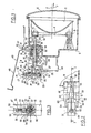
- - La figure 1 montre une vue d'un projecteur de véhicule automobile équipé d'un dispositif de réglage selon l'invention, partiellement en coupe par un plan approximativement vertical incluant ledit deuxième axe commun à la biellette, au manchon des moyens de guidage et au passage de réception de ce manchon dans les moyens supports, ici constitués par un cuvelage enveloppant le réflecteur ; un tel plan a été repéré en I-I à la figure 2.
- - La figure 2 montre une vue partielle du dispositif de réglage, de dessus, dans un sens repéré par une flèche II à la figure 1.
- - La figure 3 montre une vue du dispositif de réglage en coupe par un plan perpendiculaire au deuxième axe et repéré en III-III à la figure 1.
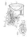
- - La figure 4 montre, en une vue analogue à celle de la figure 1, un dispositif selon l'invention télécommandable manuellement depuis le tableau de bord du véhicule ou automatiquement, de façon pilotée par des moyens détecteurs d'assiette ; cette vue est également une vue en coupe partielle par un plan approximativement vertical incluant ledit deuxième axe.
- - La figure 5 montre une vue du dispositif de réglage de la figure 4 de dessus, dans un sens repéré par une flèche V à la figure 4.
- - Figure 1 shows a view of a motor vehicle headlamp equipped with an adjustment device according to the invention, partially in section through an approximately vertical plane including said second axis common to the rod, to the sleeve of the guide means and to the passage for receiving this sleeve in the support means, here constituted by a casing enveloping the reflector; such a plan has been identified in II in FIG. 2.
- - Figure 2 shows a partial view of the adjustment device, from above, in a direction marked by an arrow II in Figure 1.
- - Figure 3 shows a view of the adjustment device in section through a plane perpendicular to the second axis and identified in III-III in Figure 1.
- - Figure 4 shows, in a view similar to that of Figure 1, a device according to the invention remotely controllable manually from the dashboard of the vehicle or automatically, in a manner controlled by means of attitude detectors; this view is also a view in partial section through an approximately vertical plane including said second axis.
- - Figure 5 shows a view of the adjustment device of Figure 4 from above, in a direction marked by an arrow V in Figure 4.
Par convention et sauf indication contraire, les différents composants des deux modes de mise en oeuvre de l'invention illustrés aux figures seront décrits dans les positions relatives qu'ils occupent sur ces figures, correspondant à un réglage initial effectué sur un véhicule vide, par exemple en atelier ou en usine.By convention and unless otherwise indicated, the various components of the two embodiments of the invention illustrated in the figures will be described in the relative positions they occupy in these figures, corresponding to an initial adjustment made on an empty vehicle, by example in workshop or factory.
Dans la mesure où les modes de mise en oeuvre de l'invention illustrés respectivement aux figures 1 à 3 et aux figures 4 et 5 comportent des composants communs, ces composants ont été repérés par les mêmes références numériques sur l'ensemble de ces figures et seront décrits de façon commune pour l'ensemble de ces figures, les spécificités propres à chacun des modes de mise en oeuvre de l'invention qui ont été illustrés étant expressément mentionnées.Insofar as the embodiments of the invention illustrated respectively in FIGS. 1 to 3 and in FIGS. 4 and 5 include common components, these components have been identified by the same reference numerals in all of these figures and will be described in common for all of these figures, the specific features of each of the embodiments of the invention which have been illustrated being expressly mentioned.
Aux figures 1 et 4, on a ainsi désigné par 1 un réflecteur de projecteur de véhicule automobile, présentant un axe optique 2 approxima tivement horizontal et monté à la rotation, autour d'un axe 3 également approximativement horizontal mais situé dans un plan 4 approximativement perpendiculaire à l'axe optique 2, sur des moyens supports ici constitués par un cuvelage 5 solidaire de la carrosserie (non représentée) du véhicule et enveloppant par l'arrière le réflecteur 1 devant lequel le cuvelage 5 est fermé par une glace transparente 6 approximativement perpendiculaire à l'axe optique 2 ; ces notions d'avant et d'arrière s'entendent pas référence à un sens déterminé 7 d'émission de lumière par le projecteur, lequel sens 7 est parallèle à l'axe optique 2 et coïncide approximativement avec le sens de marche avant du véhicule ; on remarquera qu'au lieu d'être solidaire du cuvelage 5, la glace 6 pourrait être solidaire du réflecteur 1, d'une façon connue.In FIGS. 1 and 4, a motor vehicle headlamp reflector is thus designated by 1, having an
L'axe 3 est par exemple défini, de façon connue et non illustrée dans le détail, par deux rotules portées de façon solidaire mais réglable par le cuvelage 5, à un niveau inférieur du réflecteur et en arrière de celui-ci de façon décalée par rapport à l'axe 3, et par exemple à un niveau supérieur du réflecteur 1, vers l'arrière de celui-ci, ce réflecteur coopère par ailleurs, par l'intermédiaire d'une autre articulation à rotule 8, avec une extrémité 9 d'une biellette approximativement rectiligne 10 guidée au coulissement par rapport au cuvelage 5, en arrière du réflecteur 1, suivant un axe 11 approximativement perpendiculaire au plan 4 et par rapport auquel la biellette 10, normalement rectiligne, peut fléchir légèrement par élasticité naturelle du matériau la constituant, tel qu'une matière plastique, pour s'accommoder du fait qu'un réglage de l'orientation du réflecteur 1, par pivotement autour de l'axe 3 par rapport au cuvelage 5, s'accompagne d'un mouvement circulaire de l'articulation à rotule 8 autour de cet axe 3, ce mouvement ne pouvant être considéré qu'approximativement comme un mouvement de translation suivant l'axe 11.The
La biellette 10 est guidée à la translation suivant l'axe 11 par rapport au cuvelage 5 par l'intermédiaire d'un manchon 12 lui-même engagé, avec possibilité de déplacement suivant l'axe 11, dans un passage de réception 13 aménagé à cet effet, suivant l'axe 1, dans le cuvelage 5.The
Plus précisément, le passage 13 est défini par un trou aménagé suivant l'axe 11 dans le cuvelage 5 et prolongé coaxialement en arrière de celui-ci par un col 14, de forme générale de révolution autour de l'axe 11, par exemple réalisé en une seule pièce de matière plastique avec le cuvelage 5 dans le cas du mode de mise en oeuvre de l'invention illustré aux figures 1 à 3, le passage 13 présente intérieurement, c'est-à-dire vers l'axe 11, un taraudage hélicoïdal 15 à filet trapézoïdal, d'une extrémité avant du passage 13 jusqu'à une zone proche de l'extrémité arrière de ce passage 13 où le taraudage 15 se raccorde à une face périphérique intérieure 16 du passage 13, laquelle face 16 présente une forme cylindrique de révolution autour de l'axe 11 avec un diamètre identique au diamètre maximal du taraudage 15, c'est-à-dire au diamètre à fond de filet de celui-ci ; dans le cas du mode de mise en oeuvre des figures 4 et 5, par contre, le passage 13 est délimité de son extrémité avant à son extrémité arrière par une telle face périphérique intérieure 16 cylindrique de révolution autour de l'axe 11 avec un diamètre correspondant au diamètre maximal du taraudage 15 du mode de mise en oeuvre illustré aux figures 1 à 3, si bien que le passage 13 du mode de mise en oeuvre illustré aux figures 4 et 5 peut être obtenu par usinage d'un cuvelage 5 initialement réalisé en vue de la mise en oeuvre de l'invention selon les figures 1 à 3, de façon à en éliminer le taraudage 15.More specifically, the
Le manchon 12 présente quant à lui, dans le sens d'un éloignement par rapport à l'axe 11, un filetage hélicoïdal 17 complémentaire du taraudage 16 et présentant comme lui une section de filet trapézoïdale ; dans le cas du mode de mise en oeuvre illustré aux figures 1 à 3, ce filetage 17 est en prise avec le taraudage 15 de façon à lier de façon indissociable une translation du manchon 12 à l'intérieur du passage 13, suivant l'axe 11, à une rotation relative autour de cet axe alors que dans le cas du mode de mise en oeuvre illustré aux figures 4 et 5, le taraudage 17 coulisse librement, suivant l'axe 11, contre la face périphérique intérieure 16 du passage 13 avec laquelle il est en contact par les sommets 18 de filet, d'enveloppe cylindrique de révolution autour de l'axe 11 avec un diamètre sensiblement identique à celui de la face périphérique intérieure 16 du passage 13.The
Dans une zone du manchon 12 placée en regard de la face périphérique intérieure 16 considérée comme limitée à l'arrière du passage 13, c'est-à-dire comme dans le cas du mode de mise en oeuvre des figures 1 à 3, le filetage 17 est interrompu et remplacé par une pluralité de crêtes 19 annulaires de révolution autour de l'axe 11 avec un diamètre maximal correspondant sensiblement à celui de la face périphérique intérieure 16 du passage 13 de façon à assurer, dans l'un et l'autre des modes de mise en oeuvre de l'invention, une étanchéité entre le manchon 12 et le passage 1 3.In an area of the
En arrière des crêtes d'étanchéité 19, le manchon 12 se prolonge hors du col 14, en présentant une face périphérique extérieure 20 cylindrique de révolution autour de l'axe 11 avec un diamètre réduit en comparaison avec le diamètre maximal des crêtes 19 et du filetage 7, jusqu 'à son raccordement solidaire avec une équerre 21 avantageusement réalisée en une seule pièce de matière plastique avec le manchon 12 ; cette équerre 21 présente une première aile 22 ; qui est approximativement plane et perpendiculaire à l'axe 11 et à laquelle le manchon 12 se raccorde directement, et une deuxième aile 23 quant à elle parallèle à l'axe 11, approximativement horizontale et décalée vers le haut par rapport à celui-ci que l'on se réfère aux figures 1 à 3 ou aux figures 4 et 5, et disposée en arrière de la première aile 22 un maintien rigide des deux équerres 21 et 22 dans leur perpendicularité relative est assuré par deux joues plates 24 et 25 solidaires des deux ailes 22 et 23 et avantageusement réalisées en une seule pièce avec ces dernières, lesquelles joues 24 et 25 sont perpendiculaires aux deux ailes 22 et 23 et disposées parallèlement entre elles respectivement de part et d'autre de l'axe 11 ; ces deux ailes 23 et 24 s'étendent au-dessus comme au-dessous de l'aile 23 et, dans le cas du mode de mise en oeuvre des figures 1 à 3, constituent des moyens de préhension manuelle au moyen desquels on peut aisément faire tourner le manchon 12 à l'intérieur du passage 13 pour déplacer le manchon 12 à la translation suivant l'axe 11 par rapport au cuvelage 5, dans un sens ou dans l'autre en fonction du sens dans lequel on fait ainsi tourner le manchon 12 autour de l'axe 11.Behind the
En dessous de l'aile 23, c'est-à-dire dans une zone dans laquelle elles raccordent entre elles les deux ailes 22 et 23 de l'équerre 21, les deux joues 24 et 25 présentent des encoches respectives 26 recevant, en un montage tourillonnant autour d'un axe 27 décalé vers le bas par rapport à l'axe 11 mais situé dans un plan (non illustré) perpendiculaire à cet axe 11, des ergots latéraux respectifs tels que 28 d'un levier 29 comportant deux bras plats 30 et 31 disposés sensiblement à 90° l'un par rapport à l'autre et concourant mutuellement suivant l'axe 27 commun aux ergots tels que 28.Below the
Si l'on se réfère à l'orientation du levier 29 illustrée aux figures 1 et 4, le bras 30 est parallèle à la deuxième aile 23 de l'équerre 21, sous cette aile 23 et en arrière de l'axe 27 alors que le bras 31 est approximativement parallèle à l'aile 22 de l'équerre 21, en arrière de cette aile 22 et au-dessus de l'axe 17 tout en restant toutefois en dessous de l'axe 11.If one refers to the orientation of the
Selon cet axe 11, le bras 31 est articulé, autour d'un axe 32 perpendiculaire à l'axe 11 et parallèle à l'axe 27, à une deuxième extrémité 33 de la biellette 10 avec laquelle le levier à deux bras 29 est avantageusement réalisé en une seule pièce d'une matière plastique dans laquelle l'articulation autour de l'axe 32 est définie par un amincissement localisé ; cette extrémité 33 de la biellette 10 est située en arrière du manchon 12, que la biellette 10 traverse de part en part par un alésage 34 assurant également, au moins de façon localisée, un guidage de la biellette 10 au coulissement relatif suivant l'axe 11 ; à cet effet, alors que la biellette 10 présente une face périphérique extérieure 35 cylindrique de révolution autour de l'axe 11 avec un diamètre déterminé, constant, de la proximité immédiate de son extrémité 9 à la proximité immédiate de son extrémité 33, l'alésage 34 présente vers l'axe 11 une première face périphérique intérieure 36 cylindrique de révolution autour de cet axe 11 avec un diamètre sensiblement identique à celui de la face périphérique extérieure 35 de la biellette 10 dans une zone de l'alésage 34 localisée vers l'avant, alors qu'il présente une deuxième face périphérique intérieure 37 également cylindrique de révolution autour de l'axe 11 mais avec un diamètre supérieur à celui de la face 36 de cette zone localisée de l'alésage 34 jusqu'au débouché de ce dernier vers l'arrière, dans l'aile 22 de l'équerre 21 de façon à autoriser un léger fléchissement de la biellette 10 par rapport à l'axe 11 lors d'une rotation du levier 29 autour de l'axe 27 par rapport aux deux joues 24 et 25 ; les deux faces 36 et 37 de l'alésage 34 sont raccordées mutuellement par un épaulement non référencé, annulaire de révolution autour de l'axe 11 et tourné vers l'arrière.According to this
Vers le haut, c'est-à-dire directement en regard de l'aile 23 de l'équerre 21 suivant un axe 38 orienté approximativement verticalement si l'on se réfère aux figures 1 à 3 et aux figures 4 à 5, et plus précisément perpendiculaire à l'axe 11 ainsi qu'à un plan 39 ici horizontal incluant l'axe 27, le bras 30 du levier 29 présente un logement sphérique 40 dans lequel est encliquetée, avec pour seule possibilité de mouvement relatif une possibilité de rotation relative autour d'un point 41 situé à l'intersection de l'axe 38 et du plan 30 et matérialisant le centre du logement 40, une rotule 42 que porte de façon solidaire une extrémité 43 d'une tige filetée 44 d'axe 38, qui est vissée dans un alésage 45, taraudé complémentairement, aménagé suivant l'axe 38 dans l'aile 23 de l'équerre 21 et, au-dessus de cette aile 23, dans un rebord annulaire 46 que celle-ci porte de façon solidaire vers le haut ; ce rebord 46 est avantageusement réalisé en une seule pièce de matière plastique avec l'aile 23 de l'équerre 21 ; au-dessus du rebord 46, entre les joues 24 et 25, la tige filetée 44 présente une autre extrémité 47 présentant une conformation telle qu'elle puisse venir en prise avec un tournevis ou outil analogue introduit par le dessus, suivant l'axe 38, à travers un trou 48 aménagé dans une paroi telle qu'une tôle 49 solidaire de la carrosserie (non représentée) du véhicule et enveloppant le cuvelage vers le haut ; le trou 48 est calibré de telle sorte que l'introduction du tournevis ou outil analogue en vue de manoeuvrer la tige 44 ne soit possible que lorsque l'extrémité 47 de cette dernière est placée rigoureusement en regard du trou 48, suivant l'axe 38 occupant une orientation verticale ; dans l'exemple illustré, on a ainsi prévu à l'extrémité 47 de la tige 44 une tête six pans 50 pourvue d'un fraisage 51 de réception d'une 15 lame de tournevis, à titre d'exemple non limitatif.Upwards, that is to say directly opposite the
On conçoit ainsi, qu'en tournant volontairement la tête 50 de la tige 44 au moyen d'une tournevis ou outil analogue introduit par le trou 48, et en faisant ainsi tourner la tige 44 à l'intérieur de l'alésage taraudé 45, on provoque un déplacement du bras 30 du levier 29 vers le haut ou vers le bas par pivotement du levier 29 autour de l'axe 27, avec mouvement simultané du bras 31 du levier 29 vers l'avant ou vers l'arrière et, du fait de l'articulation du bras 31 sur la biellette 10 autour de l'axe 32, un mouvement de cette biellette 10 vers l'avant ou vers l'arrière se traduisant lui-même par un pivotement du réflecteur 1 dans un sens ou dans l'autre autour de l'axe 3 par rapport au cuvelage 5, d'une façon voisine de ce qui a été décrit dans le brevet français précité de la Demanderesse.It is thus conceivable that, by voluntarily turning the
Ceci correspond à une possibilité de réglage fin de l'orientation du réflecteur 1, réalisé généralement en usine ou en atelier alors que le véhicule est vide.This corresponds to a possibility of fine adjustment of the orientation of the reflector 1, generally carried out in the factory or in the workshop while the vehicle is empty.
On remarquera que, du fait du mode d'articulation du bras 30 du levier 29 au moyen d'une rotule sur l'extrémité 43 de la tige 44, ce mouvement peut s'accompagner d'un léger décalage des ergots 28 du levier 29 dans les encoches telles que 26 prévues pour les recevoir dans les joues 24 et 25, vers l'avant ou vers l'arrière ; les encoches telles que 26 présentent à cet effet une forme oblongue suivant une direction approximativement horizontale, d'une façon aisément déterminable par un Homme du métier qui comprendra également que le décalage ainsi subi par l'axe 27 d'articulation du levier 29 sur les joues 24 et 25 constitue un phénomène par ailleurs négligeable.It will be noted that, due to the mode of articulation of the
Pour assurer une correction du réglage fin ainsi effectué initialement sur le véhicule, pour tenir compte des changements d'assiette de celui-ci, on utilise respectivement dans le mode de mise en oeuvre des figures 1 à 3 et dans le mode de mise en oeuvre des figures 4 et 5 des moyens différents qui vont être décrits à présent.To ensure a correction of the fine adjustment thus initially carried out on the vehicle, to take account of changes in attitude thereof, use is made respectively in the embodiment of Figures 1 to 3 and in the embodiment Figures 4 and 5 of the different means which will now be described.
On s'intéressera en premier lieu au mode de mise en oeuvre des figures 1 à 3, dans lequel la correction s'effectue par rotation du manchon 12 autour de l'axe 11 à l'intérieur de l'alésage 13, cette rotation étant imprimée manuellement par préhension des joues 24 et 25 ; on conçoit aisément que, alors que la biellette 10 reste fixe suivant l'axe 11 par rapport au manchon 12 du fait que l'on n'intervient pas sur la tige filetée 44, la coopération du filetage 17 du manchon 12 avec le taraudage 15 de l'alésage 13 traduit cependant une telle action manuelle de rotation du manchon 12 à l'intérieur de l'alésage 13 par une translation de la biellette 10 suivant l'axe 11 par rapport au cuvelage 5, c'est-à-dire par une modification de l'orientation du réflecteur 1 autour de l'axe 3 par rapport à ce même cuvelage.We will first be interested in the mode of implementation of Figures 1 to 3, in which the correction is made by rotation of the
On remarquera que dès lors que l'on a ainsi provoqué une rotation du manchon 12 autour de l'axe 11 à l'intérieur du passage 13, à partir d'une position dans laquelle l'axe 38 est vertical et la tête 50 de la tige filetée 44 placée directement en regard du trou 48 de la tôle 49, cette tête 50 ainsi décalée angulairement, autour de l'axe 1, par rapport au trou 48 devient inaccessible pour un tournevis ou outil analogue introduit par ce trou 48 en raison du calibrage étroit de ce dernier si bien que toute modification du réglage initial par rotation de la tige filetée 44 dans l'alésage taraudé 45, avec translation de la biellette 10 suivant l'axe 11 à l'intérieur du manchon 2, devient impossible.It will be noted that as soon as the
De préférence, des moyens sont prévus pour immobiliser, de façon amovible, le manchon 12 à la rotation à l'intérieur du passage 13 autour de l'axe 11 dans plusieurs orientations angulaires relatives déterminées.Preferably, means are provided for detachably immobilizing the
Ces moyens sont avantageusement constitués par des moyens d'encliquetage 52 comportant :
- d'une part, une pluralité d'encoches en forme de gorges rectilignes 53, 54, 55, parallèles à l'axe 11 et mutuellement décalées angulairement en référence à cet axe, ces gorges étant aménagées dans une face périphérique extérieure 56, cylindrique de révolution autour de l'axe 11, du col 14,
- d'autre part, un doigt 57 orienté radialement par rapport à l'axe 11 et tourné vers ce dernier, lequel doigt 57 est porté par le manchon 12 et sollicité élastiquement vers l'axe 11 de façon à pouvoir s'engager dans l'une des gorges 53, 54, 55 en fonction de l'orientation du manchon 12 autour de l'axe 11 à l'intérieur du passage 13, tout en pouvant se dégager de cette gorge lorsqu'on applique aux joues 24, 25 un couple de rotation autour de l'axe 11 avec un moment suffisant pour vaincre la résistance due à l'engagement élastique du doigt 57 dans la gorge respective 53, 54, 55 ; à cet effet, alors que chaque gorge 53, 54, 55 présente une section sensiblement rectangulaire lorsqu'elle est vue en coupe par un plan perpendiculaire à l'axe 11, comme c'est le cas à la figure 3, le doigt 57 présente vers l'axe 1 une extrémité convexe 58 par laquelle il s'engage dans la gorge 53, 54, 55 respective.These means are advantageously constituted by latching means 52 comprising:
- On the one hand, a plurality of notches in the form of
- On the other hand, a
Dans l'exemple illustré, le doigt 57 est réalisé en une seule pièce de matière plastique avec le manchon 12, à la face périphérique extérieure 20 duquel il est relié par un bras en porte-à-faux 59 lui communiquant la sollicitation élastique vers l'axe 11 requise par son engagement sélectif dans l'une des gorges 53, 54, 55.In the example illustrated, the
On remarquera que l'on a prévu dans l'exemple illustré trois gorges 53, 54, 55 déterminant, par engagement du doigt 57, les positions angulaires du manchon 12 à l'intérieur du passage 13 en référence à l'axe 11 correspondant respectivement a un véhicule à vide (orientation illustrée permettant le réglage fin à travers le trou 48), à une correction en vue d'une circulation à mi-charge et à une correction en vue d'une circulation à pleine charge, mais ce nombre de gorges ne constitue qu'un exemple non limitatif et pourrait être limité à deux, de même qu'il pourrait être supérieur à trois.It will be noted that in the illustrated example, three
Pour des raisons de standardisation, on retrouve dans le cas du mode de mise en oeuvre des figures 4 et 5 le doigt 57, porté par le bras en porte-à-faux 59 du manchon 12, et les gorges 53, 54, 55 de la face périphérique extérieure 56 du col 14, mais le doigt 57 ne coopère dans ce cas par son extrémité 58 qu'avec la gorge 53, le long de laquelle il peut coulisser parallèlement à l'axe 1 1 en contribuant à maintenir le manchon 12 dans une orientation telle que l'axe 38 soit vertical, tout en autorisant une translation du manchon 12 à l'intérieur du passage 13 suivant l'axe 11 en vue d'assurer une correction de l'orientation du réflecteur 1 autour de l'axe 3 par rapport au cuvelage 5 en fonction de l'assiette du véhicule.For reasons of standardization, we find in the case of the embodiment of FIGS. 4 and 5 the
En vue d'autoriser son entraînement en vue d'une telle translation, le manchon 2 porte de façon solidaire, par sa face périphérique extérieure 20, deux tourillons 60 et 61 en saillie, diamétrale ment opposés suivant un même axe 62 perpendiculaire à l'axe 1 et, dans l'exemple illustré, parallèle à l'axe 27 bien que cette condition ne soit pas impérative ; on remarquera que les tourillons 60 et 61 d'axe 62 sont également présents dans le cas du mode de mise en oeuvre de l'invention illustré aux figures 1 à 3, auquel cas ils restent cependant inutilisés.With a view to authorizing its drive for such a translation, the
Chacun des tourillons 60 et 61 est engagé, avec possibilité de rotation relative autour de l'axe 62, dans une chape 63, 64 d'un bras respectif 65, 66 d'un levier 67 présentant la forme générale d'une fourche chevauchant la face périphérique extérieure 20 du manchon 12 au niveau des tourillons 60 et 61, par le bas dans l'exemple illustré.Each of the
En dessous du manchon 12 dans cet exemple, le levier 67 est articulé autour d'un axe 68, parallèle à l'axe 62, sur un berceau 69 solidaire du cuvelage 5 avec lequel il est avantageusement réalisé en une seule pièce de matière plastique à cet effet, le levier 67 présente par exemple deux tourillons tels que 70 disposés suivant l'axe 68 et reçus dans des chapes respectives telles que 71 du berceau 69 ; on remarquera qu'une rotation du levier 67 autour de l'axe 68 par rapport au berceau 69, dans un sens ou dans l'autre, se traduit par un coulissement du manchon 12 à l'intérieur du passage 13 suivant l'axe 11 dans un sens ou dans l'autre, respectivement, les chapes 63 et 64 des bras 65 et 66 du levier 67 étant oblongues suivant une direction radiale en référence à l'axe 68 pour tenir compte de ce qu'elles se déplacent suivant un arc de cercle centré sur cet axe alors que le tourillons 60 et 61 ne peuvent accomplir qu'un mouvement rectiligne suivant l'axe 11.Below the
A l'intérieur du berceau 69, à l'opposé de l'axe 62 par rapport à l'axe 68, le levier 67 présente vers l'arrière un logement 72 susceptible de recevoir, par encliquetage élastique, une rotule 73 que porte de façon solidaire une extrémité 74 d'une tige 75 d'un vérin 76 reçu de façon solidaire par le berceau 69, en arrière du levier 67, dans une position telle que sa tige 75 présente un axe 77 parallèle à l'axe 11 et suivant lequel cette tige 75 peut se déplacer à la translation lorsqu'on actionne le vérin 76 ; on remarquera que le logement 72 présente une forme oblongue suivant une direction radiale en référence à l'axe 68 pour s'accommoder de ce que le levier 67 ne peut que pivoter autour de cet axe alors que la rotule 73 de l'extrémité 74 de la tige 75 du vérin 76 ne peut quant à elle se déplacer qu'à la translation suivant l'axe 77 ; toutefois, suivant cet axe 77, la rotule 73 est reçue étroitement dans le logement 72 de telle sorte que la tige 75 du vérin 76 et le levier 67 se déplacent à l'unisson.Inside the
Le vérin 76 peut être raccordé, de façon connue en soi et non représentée, soit à des moyens de commande manuelle placés au tableau de bord du véhicule, soit à des capteurs d'assiette de ce véhicule pour autoriser alors une correction automatique d'un réglage initial effectué, en usine ou en atelier, par rotation de la tige filetée 44 dans l'alésage 45 de l'aile 23 de l'équerre 21 afin de tenir compte de l'assiette du véhicule ; de façon connue en soi, le vérin 76 peut être mécanique ou hydraulique.The
On remarquera que toute translation de la tige 75 du vérin 76 suivant l'axe 77 alors que le manchon 12 occupait initialement dans le passage 13 une position correspondant à un strict alignement de l'axe 38 avec le trou 48 se traduit par l'introduction d'un décalage entre l'axe 38 et le trou 48, c'est-à-dire par une impossibilité d'actionner à nouveau la tête 50 de la tige filetée 44 au moyen d'un tournevis ou outil analogue introduit par ce trou 48.Note that any translation of the
On remarquera également que la coopération du manchon 12 par les tourillons 60 et 61 avec le levier 67, coopérant lui-même par les tourillons tels que 70 avec les chapes telles que 71 du berceau 69, contribue à maintenir l'axe 38 dans une orientation constante autour de l'axe 11 par rapport au cuvelage 5, a savoir dans l'exemple illustré dans une orientation verticale, correspondant également à l'engagement de l'extrémité 58 du doigt 57 dans la gorge 53 ; les gorges 54 et 55 sont dénuées de fonction dans ce mode de mise en oeuvre de l'invention, de même que le berceau 69, prévu également dans le cas du mode de réalisation des figures 1 à 3 pour des raisons de standardisation de la fabrication du cuvelage 5 est dénué de fonction dans ce mode de mise en oeuvre illustré aux figures 1 à 3.It will also be noted that the cooperation of the
Naturellement, les modes de mise en oeuvre de l'invention qui viennent d'être décrit ne constituent que des exemples non limitatifs ; on remarquera cependant que ces modes de mise en oeuvre présentent l'avantage important d'être accessibles à partir d'un même cuvelage 5, y compris les éléments tels que le col 14 et le berceau 69 de préférence réalisés en une seule pièce avec lui, d'un même manchon 12 considéré dans son ensemble, c'est-à-dire avec les éléments avantageusement réalisés en une seule pièce avec lui tels que l'équerre 21, les joues 24 et 25 et le bras 59 portant le doigt 57, et d'une même biellette 10 considérée dans son ensemble avec les éléments avantageusement réalisés en une pièce avec elle, a savoir le levier 29 et les moyens de guidage de celui-ci à la rotation autour de l'axe 27 par rapport aux joues 24 et 25 et d'articulation sur la rotule 42 de la tige filetée 44 elle-même conservée sous une forme inchangée ; à partir de ces pièces standardisées, le choix d'un mode de mise en oeuvre propre à une télécommande, illustré aux figures 4 et 5, se traduit simplement par la suppression du taraudage 15 du passage 13 du cuvelage 5 et par le montage du levier 67, du vérin 76 et des moyens de liaison de ce dernier avec le tableau de bord du véhicule ou avec des capteurs d'assiette du véhicule, ce qui est particulièrement simple.Naturally, the embodiments of the invention which have just been described constitute only nonlimiting examples; it will be noted however that these modes of implementation have the significant advantage of being accessible from the
Claims (10)
- une biellette (10) susceptible d'être orientée, par rapport aux moyens supports (5), suivant un deuxième axe (11) approximativement perpendiculaire à un plan (4) incluant le premier axe (3), ladite biellette (10) présentant une première extrémité (9) susceptible d'être liée au réflecteur (1) en un point (8) décalé par rapport au premier axe (3), et une deuxième extrémité (33),
- des moyens (12) de guidage de la biellette (10), portés par les moyens supports (5) et présentant un premier alésage (34) de réception et de guidage de la biellette (10) au coulissement disposé suivant le deuxième axe (11) et un deuxième alésage (45) taraudé disposé suivant un troisième axe (38) approximativement perpendiculaire au deuxième axe (11),
- une tige filetée (44) reçue dans le deuxième alésage taraudé (45) et coopérant avec lui, ladite tige filetée (44) présentant une première extrémité (47) et une deuxième extrémité (43),
- des moyens (50, 51) de manoeuvre de la tige filetée (44) à la rotation autour du troisième axe (38) dans le deuxième alésage taraudé (45), par la première extrémité (47) de la tige filetée (44),
- des moyens (29) de renvoi d'angle liant cinématiquement les deuxièmes extrémités respectives (33, 43) de la biellette (10) et de la tige filetée (44), pour traduire une rotation de la tige filetée (44) dans le deuxième alésage taraudé (43) par une translation de la biellette (10) dans le premier alésage (34),
caractérisé en ce que les moyens de guidage (12) et les moyens supports (5) sont mutuellement dissociés et présentent des moyens (12, 13, 14, 15, 16, 17) de liaison mutuelle à la translation relative suivant le deuxième axe (11) et en ce que sont prévus des moyens (24, 25, 52, 67, 76) pour régler la position des moyens de guidage (12) par rapport aux moyens supports (5) suivant le deuxième axe (11), afin d'autoriser une correction de l'orientation du réflecteur (1) en fonction de l'assiette du véhicule.1. Device for adjusting the orientation of a reflector (1) of a motor vehicle headlamp by pivoting said reflector (1) about a first axis (3) relative to support means (5), of the type comprising for this purpose:
- a link (10) capable of being oriented, relative to the support means (5), along a second axis (11) approximately perpendicular to a plane (4) including the first axis (3), said link (10) having a first end (9) capable of being linked to the reflector (1) at a point (8) offset from the first axis (3), and a second end (33),
- means (12) for guiding the rod (10), carried by the support means (5) and having a first bore (34) for receiving and guiding the rod (10) sliding disposed along the second axis ( 11) and a second threaded bore (45) disposed along a third axis (38) approximately perpendicular to the second axis (11),
a threaded rod (44) received in the second threaded bore (45) and cooperating with it, said threaded rod (44) having a first end (47) and a second end (43),
- Means (50, 51) for operating the threaded rod (44) in rotation about the third axis (38) in the second threaded bore (45), by the first end (47) of the threaded rod (44) ,
- Angle transmission means (29) kinematically linking the respective second ends (33, 43) of the link (10) and of the threaded rod (44), to translate a rotation of the threaded rod (44) in the second tapped bore (43) by a translation of the rod (10) in the first bore (34),
characterized in that the guide means (12) and the support means (5) are mutually dissociated and have means (12, 13, 14, 15, 16, 17) for mutual connection to the relative translation along the second axis (11) and in that means are provided (24, 25, 52, 67, 76) for adjusting the position guide means (12) relative to the support means (5) along the second axis (11), in order to allow correction of the orientation of the reflector (1) as a function of the attitude of the vehicle.
Applications Claiming Priority (2)
| Application Number | Priority Date | Filing Date | Title |
|---|---|---|---|
| FR8809227A FR2633885B1 (en) | 1988-07-07 | 1988-07-07 | DEVICE FOR ADJUSTING THE ORIENTATION OF A MOTOR VEHICLE PROJECTOR REFLECTOR |
| FR8809227 | 1988-07-07 |
Publications (2)
| Publication Number | Publication Date |
|---|---|
| EP0350400A1 true EP0350400A1 (en) | 1990-01-10 |
| EP0350400B1 EP0350400B1 (en) | 1992-04-15 |
Family
ID=9368187
Family Applications (1)
| Application Number | Title | Priority Date | Filing Date |
|---|---|---|---|
| EP19890401943 Expired - Lifetime EP0350400B1 (en) | 1988-07-07 | 1989-07-06 | Device for controlling the orientation of the reflector of a motor vehicle headlight |
Country Status (4)
| Country | Link |
|---|---|
| EP (1) | EP0350400B1 (en) |
| DE (1) | DE68901221D1 (en) |
| ES (1) | ES2032129T3 (en) |
| FR (1) | FR2633885B1 (en) |
Cited By (1)
| Publication number | Priority date | Publication date | Assignee | Title |
|---|---|---|---|---|
| FR2752788A1 (en) * | 1996-08-27 | 1998-03-06 | Peugeot | Motor vehicle headlamp adjuster |
Citations (4)
| Publication number | Priority date | Publication date | Assignee | Title |
|---|---|---|---|---|
| DE2237023A1 (en) * | 1972-07-28 | 1974-02-07 | Bosch Gmbh Robert | HYDROMECHANICAL ACTUATOR FOR LIGHTING RANGE CONTROL OF MOTOR VEHICLE HEADLIGHTS |
| FR2195949A5 (en) * | 1972-08-11 | 1974-03-08 | Dba | |
| FR2200808A5 (en) * | 1972-08-24 | 1974-04-19 | Bosch Gmbh Robert | |
| EP0268442A2 (en) * | 1986-11-17 | 1988-05-25 | Accurate Threaded Fasteners, Inc. | Support and adjustment mechanism for vehicle headlamp |
-
1988
- 1988-07-07 FR FR8809227A patent/FR2633885B1/en not_active Expired - Lifetime
-
1989
- 1989-07-06 DE DE8989401943T patent/DE68901221D1/en not_active Expired - Lifetime
- 1989-07-06 ES ES89401943T patent/ES2032129T3/en not_active Expired - Lifetime
- 1989-07-06 EP EP19890401943 patent/EP0350400B1/en not_active Expired - Lifetime
Patent Citations (4)
| Publication number | Priority date | Publication date | Assignee | Title |
|---|---|---|---|---|
| DE2237023A1 (en) * | 1972-07-28 | 1974-02-07 | Bosch Gmbh Robert | HYDROMECHANICAL ACTUATOR FOR LIGHTING RANGE CONTROL OF MOTOR VEHICLE HEADLIGHTS |
| FR2195949A5 (en) * | 1972-08-11 | 1974-03-08 | Dba | |
| FR2200808A5 (en) * | 1972-08-24 | 1974-04-19 | Bosch Gmbh Robert | |
| EP0268442A2 (en) * | 1986-11-17 | 1988-05-25 | Accurate Threaded Fasteners, Inc. | Support and adjustment mechanism for vehicle headlamp |
Cited By (1)
| Publication number | Priority date | Publication date | Assignee | Title |
|---|---|---|---|---|
| FR2752788A1 (en) * | 1996-08-27 | 1998-03-06 | Peugeot | Motor vehicle headlamp adjuster |
Also Published As
| Publication number | Publication date |
|---|---|
| FR2633885B1 (en) | 1991-05-24 |
| FR2633885A1 (en) | 1990-01-12 |
| ES2032129T3 (en) | 1993-01-01 |
| DE68901221D1 (en) | 1992-05-21 |
| EP0350400B1 (en) | 1992-04-15 |
Similar Documents
| Publication | Publication Date | Title |
|---|---|---|
| EP0847894B1 (en) | Vehicle headlight with reflector control device | |
| EP2308720B1 (en) | Device for adjusting a lighting and/or signalling device of an automobile and method for installing such a device | |
| EP0315504B1 (en) | Car seat with lateral supports | |
| FR2620793A1 (en) | AUTOMOBILE HEADLIGHT WITH TILTING REFLECTIVE MIRROR | |
| EP1423285B1 (en) | Device for mounting a sensor on a motor vehicle wheel rim and related mounting method | |
| EP0679553A1 (en) | Three dimensionally adjustable fixation device for a lighting or signaling vehicle device | |
| EP0291379B1 (en) | Device for controlling the orientation of a motor vehicle headlamp adjusting device | |
| EP0350400B1 (en) | Device for controlling the orientation of the reflector of a motor vehicle headlight | |
| EP0491603B1 (en) | Link between windscreen wiper arm, in particular for an automotive vehicle | |
| EP0021914A1 (en) | Windshield wiper, especially for automotive vehicles | |
| EP0597764B1 (en) | Window raiser for motor vehicle | |
| EP4011714A1 (en) | Device for attaching a buckle for seatbelt | |
| EP0985577B1 (en) | Control device for a movable part of a vehicle headlamp | |
| EP0085586B1 (en) | Lock control using a push button | |
| FR2528790A1 (en) | Rear wheel suspension for motorcycle - has adjustable pivot point on swinging link to adjust progression | |
| EP2522547B1 (en) | Leveling device for a vehicle headlamp with a bowden cable | |
| EP0374032B1 (en) | Arrangement for and procedure of especially automatic mounting of a functional or decorative assembly to an outside or front installation area of a supporting part wall | |
| EP0524105B1 (en) | Adjusting mechanism, fixedly mounted to a body, in particular for adjusting the orientation of vehicle headlights | |
| FR2702429A1 (en) | Headlamp for motor vehicle, comprising means for adjusting the orientation of the reflector and method for mounting these means | |
| FR2719651A1 (en) | Position adjuster for motor vehicle headlamp alignment | |
| FR2746743A1 (en) | Vehicle windscreen wiper arm | |
| EP2581265B1 (en) | Device for controlling a range corrector with cables | |
| WO2022128987A1 (en) | Motor vehicle steering wheel with foldable or retractable rim | |
| FR3095688A1 (en) | CONTROL UNIT FOR COMPACT AIR VENT | |
| WO2015019021A1 (en) | Mechanism for cutting off a light beam for an optical module and said optical module |
Legal Events
| Date | Code | Title | Description |
|---|---|---|---|
| PUAI | Public reference made under article 153(3) epc to a published international application that has entered the european phase |
Free format text: ORIGINAL CODE: 0009012 |
|
| AK | Designated contracting states |
Kind code of ref document: A1 Designated state(s): DE ES IT |
|
| 17P | Request for examination filed |
Effective date: 19900402 |
|
| 17Q | First examination report despatched |
Effective date: 19910703 |
|
| GRAA | (expected) grant |
Free format text: ORIGINAL CODE: 0009210 |
|
| AK | Designated contracting states |
Kind code of ref document: B1 Designated state(s): DE ES IT |
|
| REF | Corresponds to: |
Ref document number: 68901221 Country of ref document: DE Date of ref document: 19920521 |
|
| ITF | It: translation for a ep patent filed |
Owner name: SOCIETA' ITALIANA BREVETTI S.P.A. |
|
| REG | Reference to a national code |
Ref country code: ES Ref legal event code: FG2A Ref document number: 2032129 Country of ref document: ES Kind code of ref document: T3 |
|
| PLBE | No opposition filed within time limit |
Free format text: ORIGINAL CODE: 0009261 |
|
| STAA | Information on the status of an ep patent application or granted ep patent |
Free format text: STATUS: NO OPPOSITION FILED WITHIN TIME LIMIT |
|
| 26N | No opposition filed | ||
| PGFP | Annual fee paid to national office [announced via postgrant information from national office to epo] |
Ref country code: ES Payment date: 19990714 Year of fee payment: 11 |
|
| PGFP | Annual fee paid to national office [announced via postgrant information from national office to epo] |
Ref country code: DE Payment date: 19990715 Year of fee payment: 11 |
|
| PG25 | Lapsed in a contracting state [announced via postgrant information from national office to epo] |
Ref country code: ES Free format text: LAPSE BECAUSE OF NON-PAYMENT OF DUE FEES Effective date: 20000707 |
|
| PG25 | Lapsed in a contracting state [announced via postgrant information from national office to epo] |
Ref country code: DE Free format text: LAPSE BECAUSE OF NON-PAYMENT OF DUE FEES Effective date: 20010501 |
|
| REG | Reference to a national code |
Ref country code: ES Ref legal event code: FD2A Effective date: 20010810 |
|
| PG25 | Lapsed in a contracting state [announced via postgrant information from national office to epo] |
Ref country code: IT Free format text: LAPSE BECAUSE OF NON-PAYMENT OF DUE FEES Effective date: 20050706 |