EP0350397B1 - Mit Mitteln zur Wiedererlangung von Rückstreu-Elektronen versehene Elektronenbombardierungs-Verdampfungsvorrichtung - Google Patents
Mit Mitteln zur Wiedererlangung von Rückstreu-Elektronen versehene Elektronenbombardierungs-Verdampfungsvorrichtung Download PDFInfo
- Publication number
- EP0350397B1 EP0350397B1 EP89401924A EP89401924A EP0350397B1 EP 0350397 B1 EP0350397 B1 EP 0350397B1 EP 89401924 A EP89401924 A EP 89401924A EP 89401924 A EP89401924 A EP 89401924A EP 0350397 B1 EP0350397 B1 EP 0350397B1
- Authority
- EP
- European Patent Office
- Prior art keywords
- output
- electrons
- electron
- power
- potential
- Prior art date
- Legal status (The legal status is an assumption and is not a legal conclusion. Google has not performed a legal analysis and makes no representation as to the accuracy of the status listed.)
- Expired - Lifetime
Links
- 238000010894 electron beam technology Methods 0.000 claims description 6
- 239000002184 metal Substances 0.000 claims description 4
- 229910052751 metal Inorganic materials 0.000 claims description 4
- 238000010438 heat treatment Methods 0.000 description 3
- 230000000694 effects Effects 0.000 description 2
- 230000008020 evaporation Effects 0.000 description 2
- 238000001704 evaporation Methods 0.000 description 2
- 238000000034 method Methods 0.000 description 2
- RYGMFSIKBFXOCR-UHFFFAOYSA-N Copper Chemical compound [Cu] RYGMFSIKBFXOCR-UHFFFAOYSA-N 0.000 description 1
- 230000001609 comparable effect Effects 0.000 description 1
- 229910052802 copper Inorganic materials 0.000 description 1
- 239000010949 copper Substances 0.000 description 1
- 238000011084 recovery Methods 0.000 description 1
- 230000035939 shock Effects 0.000 description 1
- 238000001228 spectrum Methods 0.000 description 1
Images

Classifications
-
- H—ELECTRICITY
- H01—ELECTRIC ELEMENTS
- H01J—ELECTRIC DISCHARGE TUBES OR DISCHARGE LAMPS
- H01J37/00—Discharge tubes with provision for introducing objects or material to be exposed to the discharge, e.g. for the purpose of examination or processing thereof
- H01J37/30—Electron-beam or ion-beam tubes for localised treatment of objects
- H01J37/305—Electron-beam or ion-beam tubes for localised treatment of objects for casting, melting, evaporating, or etching
- H01J37/3053—Electron-beam or ion-beam tubes for localised treatment of objects for casting, melting, evaporating, or etching for evaporating or etching
Definitions
- the present invention relates to an evaporator electronically bombarded with means recovery of backscattered electrons.
- a target usually metal
- an electron beam In an electron bombardment evaporator, a target (usually metal) is heated under the impact of an electron beam.
- an evaporator comprises an electron gun 10 emitting a jet of electrons 12 accelerated under a few tens of kilovolts.
- a continuous supply 18 generates on an output S1 a potential difference applied between the cathode 20 and the anode 22 of the electron gun 10.
- the beam path 12 is bent by a magnetic field B by some 10 -3 Tesla (that is to say a few tens of Gauss). The beam 12 thus directed strikes the target 14 contained in a crucible 16 and thus heats it up to its evaporation temperature.
- power supply 18 provides an Io current of 10A for a voltage Vo of -30 kV between cathode 20 and anode 22 for example.
- the radiating electron beam 12 target 14 then has an incident power Po of 300 kW. But this incident power Po is not not fully consumed by the heating of the target 14. In particular, part of the power Po is lost as a reissue by the target 14 of so-called secondary electrons 24.
- the trajectories 24 of these secondary electrons are also bent by the magnetic field B .
- the energy spectrum and the spatial distribution of these secondary electrons essentially depend on three parameters: the energy of the incident beam 12, the incident angle and the atomic number of the target 14.
- the object of the present invention is to recover a fraction of the energy carried by these backscattered type secondary electrons so to reuse it in the bombing process.
- the means for collecting said backscattered electrons consist in a metal trapping cage collecting everything electron due to backscattering occurring inside of said cage.
- This trapping cage is adapted to the shape of the jet of backscattered electrons by the target. It can be cylindrical or parallelepipedic.
- the trapping cage is parallelepipedic, an opening being made in the cage for allow the introduction of the backscattered electron jet.
- Figure 2 shows schematically an evaporator provided with a device according to the invention.
- the trajectories 24 of the secondary electrons emitted by the target 14 are bent under the effect of the applied magnetic field B .
- means 26 are placed to collect the "secondary" electrons.
- these means 26 are formed of a metal trapping cage 28 brought to a potential Vc.
- a metal trapping cage 28 brought to a potential Vc.
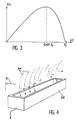
- FIG. 3 shows schematically variations in the power Pc recovered by a device according to the invention depending on the value of Vc.
- this power Pc presents in this example a maximum for a value of Vc substantially equal to 0.65 Vo.
- this value is such that only the electrons backscattered are captured by the trapping cage 28. Low energy "true secondary” electrons are repelled by the trapping cage 28.
- the bombardment electronic is done in the form of tablecloth.
- the electron beam 12 therefore strikes the target 14 along a strip; the effectiveness of the temperature rise is then increased since the electrons are distributed over target 14.
- the electrons secondary are also returned as a tablecloth.
- Figure 4 shows schematically the trapping cage 28 in perspective.
- the tablecloth of backscattered electrons is attracted while the true secondary electrons are repelled.
- a power supply 30 is connected by a first output S2 to the cage trapping 28. This S2 output is brought to potential Vc.
- a second output S3 of this power supply 30 is connected to the output S1 of the power supply 18. This second output S3 is therefore brought to the potential Vo which acts as a reference potential.
- the power recovered Pc by the device according to the invention is not equal to the power effective Pe of backscattered electrons captured by the trapping cage. From the latter we must subtract the braking power Pf spent by electrons upon arrival in the trapping cage 28. The power recovered Pc by the device is therefore equal to Pe-Pf.
- the power supply 30 providing the additional (39 kW), the power can be reused total (111 kW) lost in the evaporation process.
Landscapes
- Physics & Mathematics (AREA)
- Engineering & Computer Science (AREA)
- Plasma & Fusion (AREA)
- Chemical & Material Sciences (AREA)
- Analytical Chemistry (AREA)
- Physical Vapour Deposition (AREA)
- Electron Sources, Ion Sources (AREA)
Claims (3)
- Mit Mitteln zur Wiedererlangung von Elektronen versehene Elektronenbombardierungs-Verdampfungsvorrichtung, die durch ein mit einem Elektronenstrahl (12) beschossenes Target (14) rückgestreut werden, wobei dieser Elektronenstrahl von einer Elektronenkanone (10) stammt, deren eine Elektrode (20) mit einem Ausgang S1 einer ersten Gleichstromversorgung (18) verbunden ist und diese Gleichstromversorgung (18) an ihrem Ausgang (S1) ein negatives Potential Vo liefert, umfassend:Einrichtungen (26) zum Sammeln der genannten rückgestreuten Elektronen, wobei diese Einrichtungen (26) auf ein Potential Vc gebracht werden, so daß die durch das Target (14) rückgestreuten Elektronen von dem genannten Einrichtungen (26) angezogen werden,eine zweite Gleichstromversorgung (30), durch einen ersten Ausgang (S2) mit Einrichtungen (26) zum Sammeln der rückgestreuten Elektronen verbunden, wobei dieser erste Ausgang (S2) auf das Potential Vc gebracht wird, die zweite Gleichstromversorgung (30) außerdem durch einen zweiten Ausgang (S3) mit dem Ausgang (S1) der ersten Versorgung (18) verbunden ist und der zweite Ausgang (S3) auf das Potential Vo gebracht wird.
- Verdampfungsvorrichtung nach Anspruch 1, dadurch gekennzeichnet, daß die Einrichtungen (26) zum Sammeln der rückgestreuten Elektronen durch einen metallischen Fangkäfig (28) gebildet werden, der jedes aufgrund einer Rückstreuung ins Innere des besagten Käfigs eintretende Elektron einfängt.
- Verdampfungsvorrichtung nach Anspruch 2, wobei der Fangkäfig 28 parallelflach bzw. quaderförmig ist.
Applications Claiming Priority (2)
| Application Number | Priority Date | Filing Date | Title |
|---|---|---|---|
| FR8809156A FR2634061B1 (fr) | 1988-07-06 | 1988-07-06 | Evaporateur a bombardement electronique muni de moyens de recuperation des electrons retrodiffuses |
| FR8809156 | 1988-07-06 |
Publications (2)
| Publication Number | Publication Date |
|---|---|
| EP0350397A1 EP0350397A1 (de) | 1990-01-10 |
| EP0350397B1 true EP0350397B1 (de) | 1998-03-04 |
Family
ID=9368141
Family Applications (1)
| Application Number | Title | Priority Date | Filing Date |
|---|---|---|---|
| EP89401924A Expired - Lifetime EP0350397B1 (de) | 1988-07-06 | 1989-07-05 | Mit Mitteln zur Wiedererlangung von Rückstreu-Elektronen versehene Elektronenbombardierungs-Verdampfungsvorrichtung |
Country Status (5)
| Country | Link |
|---|---|
| US (1) | US4958059A (de) |
| EP (1) | EP0350397B1 (de) |
| JP (1) | JP2735630B2 (de) |
| DE (1) | DE68928592T2 (de) |
| FR (1) | FR2634061B1 (de) |
Families Citing this family (3)
| Publication number | Priority date | Publication date | Assignee | Title |
|---|---|---|---|---|
| DE4028842C2 (de) * | 1990-09-11 | 1995-10-26 | Balzers Hochvakuum | Verfahren und Anordnung zur Steuerung der Bedampfungsstromdichte und/oder deren Verteilung |
| TWI363100B (en) * | 2007-10-11 | 2012-05-01 | Nat Applied Res Laboratories | Method for manufacturing substrate emitting far-infrared irradiation |
| KR102322410B1 (ko) * | 2020-03-26 | 2021-11-09 | 티오에스주식회사 | 후방산란전자 포집부를 구비한 금속-산화물 전자빔 증발원 |
Family Cites Families (9)
| Publication number | Priority date | Publication date | Assignee | Title |
|---|---|---|---|---|
| US3244855A (en) * | 1963-07-19 | 1966-04-05 | United States Steel Corp | System for correcting the shift of an electron-gun beam from the desired region of impingement |
| US3390249A (en) * | 1965-09-20 | 1968-06-25 | Air Reduction | Vaporization monitoring apparatus |
| US3467057A (en) * | 1966-07-27 | 1969-09-16 | Hitachi Ltd | Electron beam evaporator |
| CH566399A5 (de) * | 1973-05-26 | 1975-09-15 | Balzers Patent Beteilig Ag | |
| US3876879A (en) * | 1973-11-09 | 1975-04-08 | Calspan Corp | Method and apparatus for determining surface characteristics incorporating a scanning electron microscope |
| US4309589A (en) * | 1978-07-25 | 1982-01-05 | National Research Institute For Metals | Method and apparatus for electron beam welding |
| US4262160A (en) * | 1979-07-18 | 1981-04-14 | Jersey Nuclear-Avco Isotopes, Inc. | Evaporator feed |
| US4551844A (en) * | 1983-04-05 | 1985-11-05 | Jersey Nuclear-Avco Isotopes, Inc. | Demodulation of vapor density |
| US4760254A (en) * | 1985-06-07 | 1988-07-26 | Pierce Daniel T | Apparatus and method for electron spin polarization detection |
-
1988
- 1988-07-06 FR FR8809156A patent/FR2634061B1/fr not_active Expired - Lifetime
-
1989
- 1989-06-30 US US07/374,474 patent/US4958059A/en not_active Expired - Fee Related
- 1989-07-05 EP EP89401924A patent/EP0350397B1/de not_active Expired - Lifetime
- 1989-07-05 JP JP1173851A patent/JP2735630B2/ja not_active Expired - Lifetime
- 1989-07-05 DE DE68928592T patent/DE68928592T2/de not_active Expired - Fee Related
Non-Patent Citations (1)
| Title |
|---|
| Sequoia, Lausanne, CH; S. SCHILLER et al.: "High rate electron beam evaporation" * |
Also Published As
| Publication number | Publication date |
|---|---|
| DE68928592D1 (de) | 1998-04-09 |
| EP0350397A1 (de) | 1990-01-10 |
| FR2634061B1 (fr) | 1991-04-05 |
| JP2735630B2 (ja) | 1998-04-02 |
| FR2634061A1 (fr) | 1990-01-12 |
| US4958059A (en) | 1990-09-18 |
| DE68928592T2 (de) | 1998-09-17 |
| JPH02112142A (ja) | 1990-04-24 |
Similar Documents
| Publication | Publication Date | Title |
|---|---|---|
| US10825642B2 (en) | X-ray source with ionisation tool | |
| FR3040442B1 (fr) | Propulseur ionique a grille avec propergol solide integre | |
| FR2485863A1 (fr) | Dispositif a plasma d'arc sous vide | |
| FR2537777A1 (fr) | Procede et dispositif d'implantation de particules dans un solide | |
| JP2009544120A5 (de) | ||
| Shaim et al. | Characterization of laser-generated aluminum plasma using ion time-of-flight and optical emission spectroscopy | |
| CN106990085A (zh) | 一种监测霍尔推力器羽流区产物组分的装置 | |
| Wieland et al. | EUV and fast ion emission from cryogenic liquid jet target laser-generated plasma | |
| FR2491257A1 (fr) | Source d'electrons a grande densite a excitation par laser | |
| EP0350397A1 (de) | Mit Mitteln zur Wiedererlangung von Rückstreu-Elektronen versehene Elektronenbombardierungs-Verdampfungsvorrichtung | |
| US8253123B2 (en) | Method and device for generating EUV radiation or soft X-rays with enhanced efficiency | |
| Amoruso et al. | High fluence laser ablation of aluminum targets: Time-of-flight mass analysis of plasmas produced at wavelengths 532 and 355 nm | |
| US6429439B2 (en) | Organic field ionization source | |
| JP2019002750A (ja) | 光電子分光装置用試料ホルダ | |
| Pinayev et al. | First results of the SRF gun test for CeC PoP experiment | |
| EP0379243A1 (de) | Photovervielfacher mit einer grossen ersten Dynode und mit einem, aus aufgeschichteten Dynoden bestehendem Vervielfacher | |
| Khalil et al. | Generation of ion beams on a steel surface by laser radiation at various wavelengths under the presence of an applied electric field | |
| WO2014095888A1 (fr) | Dispositif d'optique electronique | |
| Krushelnick et al. | Particle acceleration using intense laser produced plasmas | |
| Kormann et al. | A Photoelectron Source for the Study of Smith-Purcell Radiation | |
| Razzaq et al. | Investigation of charged particles dynamics along with self-generated electric and magnetic fields in axially resolved laser-induced magnesium plasma | |
| US4551844A (en) | Demodulation of vapor density | |
| Delle Side et al. | A proton source via laser ablation of hydrogenated targets | |
| Mair | On the role of secondary electrons in liquid metal ion sources | |
| EP0214031A1 (de) | Ionenquelle mit magnetischem Spiegel |
Legal Events
| Date | Code | Title | Description |
|---|---|---|---|
| PUAI | Public reference made under article 153(3) epc to a published international application that has entered the european phase |
Free format text: ORIGINAL CODE: 0009012 |
|
| AK | Designated contracting states |
Kind code of ref document: A1 Designated state(s): DE GB |
|
| 17P | Request for examination filed |
Effective date: 19900615 |
|
| 17Q | First examination report despatched |
Effective date: 19960605 |
|
| GRAG | Despatch of communication of intention to grant |
Free format text: ORIGINAL CODE: EPIDOS AGRA |
|
| GRAG | Despatch of communication of intention to grant |
Free format text: ORIGINAL CODE: EPIDOS AGRA |
|
| GRAH | Despatch of communication of intention to grant a patent |
Free format text: ORIGINAL CODE: EPIDOS IGRA |
|
| GRAH | Despatch of communication of intention to grant a patent |
Free format text: ORIGINAL CODE: EPIDOS IGRA |
|
| GRAA | (expected) grant |
Free format text: ORIGINAL CODE: 0009210 |
|
| AK | Designated contracting states |
Kind code of ref document: B1 Designated state(s): DE GB |
|
| REF | Corresponds to: |
Ref document number: 68928592 Country of ref document: DE Date of ref document: 19980409 |
|
| GBT | Gb: translation of ep patent filed (gb section 77(6)(a)/1977) |
Effective date: 19980508 |
|
| PGFP | Annual fee paid to national office [announced via postgrant information from national office to epo] |
Ref country code: GB Payment date: 19980626 Year of fee payment: 10 |
|
| PGFP | Annual fee paid to national office [announced via postgrant information from national office to epo] |
Ref country code: DE Payment date: 19980711 Year of fee payment: 10 |
|
| PLBE | No opposition filed within time limit |
Free format text: ORIGINAL CODE: 0009261 |
|
| STAA | Information on the status of an ep patent application or granted ep patent |
Free format text: STATUS: NO OPPOSITION FILED WITHIN TIME LIMIT |
|
| 26N | No opposition filed | ||
| PG25 | Lapsed in a contracting state [announced via postgrant information from national office to epo] |
Ref country code: GB Free format text: LAPSE BECAUSE OF NON-PAYMENT OF DUE FEES Effective date: 19990705 |
|
| GBPC | Gb: european patent ceased through non-payment of renewal fee |
Effective date: 19990705 |
|
| PG25 | Lapsed in a contracting state [announced via postgrant information from national office to epo] |
Ref country code: DE Free format text: LAPSE BECAUSE OF NON-PAYMENT OF DUE FEES Effective date: 20000503 |