EP0349985A1 - Abstandshalter für Bewehrungsmatten und Spiralbewehrungskörben - Google Patents
Abstandshalter für Bewehrungsmatten und Spiralbewehrungskörben Download PDFInfo
- Publication number
- EP0349985A1 EP0349985A1 EP89112212A EP89112212A EP0349985A1 EP 0349985 A1 EP0349985 A1 EP 0349985A1 EP 89112212 A EP89112212 A EP 89112212A EP 89112212 A EP89112212 A EP 89112212A EP 0349985 A1 EP0349985 A1 EP 0349985A1
- Authority
- EP
- European Patent Office
- Prior art keywords
- spacer
- wire
- axis
- mesh
- shank portion
- Prior art date
- Legal status (The legal status is an assumption and is not a legal conclusion. Google has not performed a legal analysis and makes no representation as to the accuracy of the status listed.)
- Granted
Links
- 125000006850 spacer group Chemical group 0.000 title claims abstract description 94
- 230000002787 reinforcement Effects 0.000 title claims abstract description 33
- 230000003014 reinforcing effect Effects 0.000 title description 6
- 238000009434 installation Methods 0.000 claims abstract description 17
- 239000000463 material Substances 0.000 claims description 7
- 229910000639 Spring steel Inorganic materials 0.000 claims description 5
- 230000001154 acute effect Effects 0.000 claims description 3
- 239000012858 resilient material Substances 0.000 claims description 2
- 239000004567 concrete Substances 0.000 abstract description 14
- 238000004519 manufacturing process Methods 0.000 description 6
- 230000014759 maintenance of location Effects 0.000 description 5
- 239000011150 reinforced concrete Substances 0.000 description 5
- 229910000831 Steel Inorganic materials 0.000 description 3
- 230000006378 damage Effects 0.000 description 3
- 239000010959 steel Substances 0.000 description 3
- RTZKZFJDLAIYFH-UHFFFAOYSA-N Diethyl ether Chemical compound CCOCC RTZKZFJDLAIYFH-UHFFFAOYSA-N 0.000 description 2
- WYTGDNHDOZPMIW-RCBQFDQVSA-N alstonine Natural products C1=CC2=C3C=CC=CC3=NC2=C2N1C[C@H]1[C@H](C)OC=C(C(=O)OC)[C@H]1C2 WYTGDNHDOZPMIW-RCBQFDQVSA-N 0.000 description 2
- 230000004048 modification Effects 0.000 description 2
- 238000012986 modification Methods 0.000 description 2
- OKTJSMMVPCPJKN-UHFFFAOYSA-N Carbon Chemical compound [C] OKTJSMMVPCPJKN-UHFFFAOYSA-N 0.000 description 1
- 206010017472 Fumbling Diseases 0.000 description 1
- 208000027418 Wounds and injury Diseases 0.000 description 1
- 229910052799 carbon Inorganic materials 0.000 description 1
- 238000010276 construction Methods 0.000 description 1
- 210000005224 forefinger Anatomy 0.000 description 1
- 208000014674 injury Diseases 0.000 description 1
- 230000000670 limiting effect Effects 0.000 description 1
- 238000000034 method Methods 0.000 description 1
- 210000003813 thumb Anatomy 0.000 description 1
Images
Classifications
-
- E—FIXED CONSTRUCTIONS
- E04—BUILDING
- E04C—STRUCTURAL ELEMENTS; BUILDING MATERIALS
- E04C5/00—Reinforcing elements, e.g. for concrete; Auxiliary elements therefor
- E04C5/16—Auxiliary parts for reinforcements, e.g. connectors, spacers, stirrups
- E04C5/18—Spacers of metal or substantially of metal
Definitions
- the present invention relates to a spacer for concrete wire reinforcement and, more particularly, to a reinforcement spacer which is adapted for use with all mesh and cage spacings and wire gauges and which is readily installed by hand.
- a spring-wire spacer intended for use with variable-spacing wire mesh is described in U. S. Patent No. 3,722,164, issued on March 27, 1973.
- This spacer includes a serpentine part adapted to be engaged with the horizontal wire of the reinforcing mesh and two extension parts, one which protrudes outward from the serpentine part and acts as a spacing jack and the other which serves as a spring- loaded lever arm having a hook at its upper end to engage a vertical wire to clip the spacer on the mesh.
- this spacer has other disadvantages that impair its usefulness.
- the spacing jack terminates in a sharp end, which can damage the mold surfaces during fabrication and which, if extending through the concrete surface as sometimes occurs, can damage adjacent materials during shipment and can also result in injury to workmen during handling.
- the spacing jack is a single wire protrusion extending at a right angle to the mesh. As a result, it can impede the placement of the mold over the wire mesh cage during fabrication and is also susceptible of being bent over. In the latter case, the jack no longer provides the proper positioning of the mesh relative to the mold surface.
- the lever arm which is gripped by hand during installation of the spacer, affords only the thickness of the spring-wire as a hand grip, and this can lead to difficulty and lost time in installation.
- a second portion of the shank connects the U-shaped projection to the lower arm and backs against the next adjacent horizontal wire to impart a torsional retention force to the spacer when the lower arm is snapped into position behind the vertical wire.
- an improved reinforcement spacer for concrete structures which is formed as a unitary stiff, but resilient, member having an upper pigtail portion for engagement with one of a pair of intersecting reinforcement wires, a middle shank portion bearing a rounded spacing projection for engagement with the surface of a concrete mold, and a lower hook portion for engagement with the other of the intersecting pair of wires to securely clamp the spacer in place on the wire reinforcement.
- the pigtail portion preferably extends to one side of the shank portion along an axis of curvature, or spiral, and is formed such that, when hooked over a mesh wire, the shank portion inclines away from the other intersecting mesh wire at a relatively small acute angle, e.g. on the order of ten to twenty degrees or so.
- the nose-like projection of the shank portion in addition to its function of spacing the wire reinforcement from the concrete mold surface, also serves as a convenient gripping surface for ready installation of the spacer on the wire reinforcement. The worker need only grip the spacer by the nose-like projection, hook the pigtail portion over one of the intersecting wires, and then, without changing grip, swing the hook portion into engagement with the other wire by pushing on the nose-like projection.
- the spacer of the invention requires only one intersection of wires for installation, it is usable with all mesh or cage spacings. It is likewise adapted for use with all wire gauges.
- An added advantage in the latter respect is that, as wire gauge increases, the construction of the spacer is such that the retention force tending to hold the spacer in place on the wire reinforcement also increases. This means that the spacer will inherently provide higher retention forces in high-load applications, where heavy gauge reinforcement is typically used.
- the spacer is formed of a single piece of spring steel wire that is bent to define the pigtail, shank and hook portions.
- the pigtail portion preferably includes a body portion that lies in a plane inclined at an acute angle to the shank axis and terminates in an upright end portion that bends upwardly out of the plane of the body portion.
- the shank portion is deformed adjacent its lower end to form the nose-like spacing projection.
- the upper leg of the projection slopes downwardly to facilitate the free flow of concrete over the spacer and to aid in guiding the vertical placement of molds over reinforcement cages.
- the lower leg of the nose-like projection merges into the hook portion, which itself is generally U-shaped and extends to the same side of the shank portion as does the pigtail portion.
- the U-shaped channel of the hook portion preferably opens back towards the shank portion so as to provide a secure clamping engagement with the other wire of the reinforcement.
- a reinforcement spacer 10 constructed in accordance with the invention is formed as a single, unitary member including, in general, a pig tail portion 12, a shank portion 14, and a hook portion 16. It is a feature of the invention that the spacer 10 may be economically fabricated as a simple wire form of a stiff but resilient material. For example, a high carbon hard drawn steel wire (e.g. C-1065) of approximately 0.150 inches diameter has been found satisfactory for the manufacture of small to medium size reinforced concrete pipe. Other materials and wire sizes may be used to suit the strength requirements of a given application.
- a high carbon hard drawn steel wire e.g. C-1065
- Other materials and wire sizes may be used to suit the strength requirements of a given application.
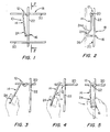
- the spacer 10 is illustrated in Figs. 1 and 2 as installed on a welded-wire mesh reinforcement 18 formed by intersecting horizontal wires 20 and vertical wires 22 (only one of which is shown).
- the shank portion 14 is deformed at the lower end thereof (as seen in Fig. 2) as an outwardly and downwardly sloping spacing, or nose, portion 24 that is bent at its lower end along a radius of curvature to extend back towards the axis of the shank 14 and then merge into the hook portion 16.
- the sloping upper leg 24a of the nose portion 24 serves to permit the free flow of concrete downward over the mesh or cage 18 without obstruction by the spacer 10.
- the spacer 10 is depicted in Figs. 1 and 2 as installed on a wire mesh or cage 18 in which the vertical wires 22 are on the inside of the horizontal wires 20. It is a feature of the invention that the spacer could be installed equally as well on a mesh or cage in which the horizontal wires are on the inside of the vertical wires. Similarly, the pigtail portion 12 could be hooked over a vertical wire 22 and the hook portion 16 engaged with a horizontal wire 20.
- the spacer 10 embodying the invention requires only one horizontal wire 20 and one vertical wire 22 for installation. Unlike certain prior art spacers, no backing wire is required to impart gripping force to the spacer. Similarly, there is no need for any specific spacing between adjacent horizontal wires 20.
- the spacer of the invention is adapted for use with all mesh spacings and with all wire gauges. No inventory of specially sized spacers is required for different mesh spacings or gauges.
- the spacer of the invention is also useful with helical cages in which the circumferential wires and the vertical wires do not intersect at right angles and in which the spacing or pitch of the circumferential wires frequently is varied to meet reinforcing design specifications.
- the manner of installation of the spacer 10 is illustrated in Figs. 3, 4, and 5, from which further advantages of the invention will be apparent.
- the worker need only grip it at one point, namely the nose portion 24.
- the pigtail portion 12 may readily be slipped over a horizontal or circumferential wire 20, as shown in Fig. 3.
- the particular configuration of the pigtail portion facilitates such placement of the spacer on the wire 20.
- the spacer 10 is then slid along the wire 20 until the pigtail portion 12 contacts the intersecting vertical cross wire 22, as indicated by the arrow in Fig. 4.
- the spacer may be brought into secure clamping engagement with the wire mesh 18 by pushing the nose portion 24 in the direction of the arrow in Fig. 5 so as to move the hook portion 16 to the right (as seen in Fig. 5) and in behind the vertical wire 22.
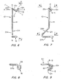
- the hook portion 16 defines a U-shaped channel 28 (see Fig. 8) which extends into the plane of Figs. 3-5 and opens back towards the shank portion 14.
- the nose portion 24 not only functions to position the wire reinforcement relative to the adjacent mold surface, but it also serves as a convenient handle by which the spacer may be gripped for installation.
- This handle function of the nose portion 24 has the very practical advantage of automatically aligning the spacer in the correct orientation for installation, thereby eliminating the time consuming fumbling and reorienting required with certain prior art devices.
- the nose also provides a relative broad gripping surface against which the worker can push when moving the hook portion 16 into engagement with the vertical wire 22 against the spring force of the spacer. This is to be contrasted with prior art spacers where only a single round wire is provided as a gripping surface.
- the pigtail portion 12 is preferably oriented relative to the shank portion so that, when the portion 12 is engaged with the wire 20 and moved into contact with the wire 22, as shown in Figs. 3 and 4, the shank portion 14 will be included at an angle ⁇ away from the vertical wire 22 (see Fig. 4). Then, when the nose portion 24 is pushed to the right as shown in Fig. 5, the shank portion 14 will pivot generally about the juncture between the shank portion 14 and the pigtail portion 12 and against the resilience of the material composing the spacer. This creates a spring force urging the hook portion 16 firmly against the vertical wire 22 and serves to secure the spacer on the mesh 18.
- the pigtail portion 12 preferably is formed along an axis of curvature, or spiral, A-A that extends to the right side of the shank 14 (as viewed in Fig. 6) at an angle of approximately ninety degrees to the plane B-B of the shank portion 14.
- the pigtail portion 12 preferably has a spiral-like main body 12a which lies in a front-to-back plane (C-C) and terminates in an upright portion 12b extending along an axis D-D that preferably is approximately perpendicular to plane C-C.
- the pigtail body portion 12a as viewed from the side in Fig. 7 and the top in Fig. 9, curls backwardly, away from the nose portion 24, and to the right and then returns towards forwardly to approximately the axis B-B of the shank portion 14.
- the upper tip of the pigtail portion 12b might lie approximately on the axis B-B.
- the curvature of the portion 12a should be sufficient to receive the reinforcing wire 20 when the spacer is looped over it in the manner illustrated in Figs. 3-5.
- the upright pigtail portion 12b provides a bearing surface through which the force applied to the nose portion 24 and shank portion 14 is transmitted to the wires 20 and 22 during the final installation step (Fig. 5). This configuration of the pigtail portion 12 affords an easy and quick attachment of the upper part of the spacer 10 to a welded-wire mesh or spiral cage at any one welded wire intersection.
- the specific angles for the pigtail body 12a and the upright terminal portion 12b given in connection with Figs. 6 and 7 are not limiting, but may be varied from the values given.
- the object is to provide an inclination ⁇ of the shank 14 relative to the vertical wire 22 when the spacer 10 is in the position shown in Fig. 4 that will assure a sufficient resilient force to securely clamp the spacer on the mesh when the shank 14 is pushed to the right and engaged with the vertical wire 22 as shown in Fig. 5.
- the inclination of shank 14 should not be so great as to require an unduly large installation force or to overstress the spacer material.
- the aforementioned thirty degree inclination of the pigtail body 12a and the ninety degree orientation of the pigtail terminal projection 12b produces an approximately twelve degree inclination of the shank portion 14 relative to the vertical wire 22 when the spacer is attached in the position of Fig. 4 to a 0.162 inch diameter mesh wire.
- the angle of inclination of the shank portion 14 is approximately sixteen degrees, and when attached to a 0.194 inch diameter wire the angle of inclination of shank portion 14 is approximately twenty degrees.
- the hook portion 16 extends perpendicularly to the right (as viewed in Fig. 6) from the lower, horizontal leg 24b of the nose portion 24 and lies in the plane of the member 24b.
- the hook portion 16 preferably is O-shaped in plan view (Fig. 8) and opens to the left (as viewed in Fig. 6).
- the spring force of the spacer which results from pivoting the shank portion 14 about the juncture between the pigtail portion 12 and the shank portion 14 urges the hook portion 16 firmly against the wire 22, and the U-shaped configuration and leftward-facing orientation of the hook portion 16 serves to keep the spacer from slipping off the wire 22.
- the hook portion 16 and the pigtail portion 12 are preferably in generally over-lying relation, so that an axis parallel to the shank portion 14 and passing through the center of the U-shaped channel 28 of the hook portion also passes through the curved region of the pigtail body 12a.
Landscapes
- Engineering & Computer Science (AREA)
- Architecture (AREA)
- Civil Engineering (AREA)
- Structural Engineering (AREA)
- Reinforcement Elements For Buildings (AREA)
Applications Claiming Priority (2)
| Application Number | Priority Date | Filing Date | Title |
|---|---|---|---|
| US21541188A | 1988-07-05 | 1988-07-05 | |
| US215411 | 1988-07-05 |
Publications (2)
| Publication Number | Publication Date |
|---|---|
| EP0349985A1 true EP0349985A1 (de) | 1990-01-10 |
| EP0349985B1 EP0349985B1 (de) | 1993-09-22 |
Family
ID=22802877
Family Applications (1)
| Application Number | Title | Priority Date | Filing Date |
|---|---|---|---|
| EP89112212A Expired - Lifetime EP0349985B1 (de) | 1988-07-05 | 1989-07-04 | Abstandshalter für Bewehrungsmatten und Spiralbewehrungskörben |
Country Status (4)
| Country | Link |
|---|---|
| EP (1) | EP0349985B1 (de) |
| CA (1) | CA1304596C (de) |
| DE (1) | DE68909332T2 (de) |
| ES (1) | ES2046382T3 (de) |
Cited By (2)
| Publication number | Priority date | Publication date | Assignee | Title |
|---|---|---|---|---|
| FR2817890A1 (fr) * | 2000-12-13 | 2002-06-14 | Campenon Bernard | Element de positionnement de maintien et d'ancrage d'un grillage sur un support |
| US11274447B2 (en) * | 2020-02-18 | 2022-03-15 | Hawkeyepedershaab Concrete Technologies, Inc | Lift hole forming device for concrete products |
Citations (6)
| Publication number | Priority date | Publication date | Assignee | Title |
|---|---|---|---|---|
| US1498595A (en) * | 1922-07-26 | 1924-06-24 | Daniel A Wedmore | Tying device for reenforcing rods or bars |
| US3359019A (en) * | 1966-10-13 | 1967-12-19 | Wire King Products Inc | Bar clip |
| US3722164A (en) * | 1971-02-09 | 1973-03-27 | Hawkeye Concrete Prod | Spring wire spacer, especially for spacing reenforcing mesh from the form in the manufacture of concrete structures and the like |
| US4005560A (en) * | 1972-02-11 | 1977-02-01 | Preformed Line Products Company | Reinforced concrete appliance |
| US4452026A (en) * | 1981-09-28 | 1984-06-05 | Tolliver Wilbur E | Spacer for wire reinforcement in concrete structures such as pipe |
| US4641991A (en) * | 1984-06-29 | 1987-02-10 | Yuhei Yaoita | Connector for reinforcing rods |
-
1988
- 1988-10-19 CA CA000580590A patent/CA1304596C/en not_active Expired - Lifetime
-
1989
- 1989-07-04 ES ES89112212T patent/ES2046382T3/es not_active Expired - Lifetime
- 1989-07-04 DE DE1989609332 patent/DE68909332T2/de not_active Expired - Fee Related
- 1989-07-04 EP EP89112212A patent/EP0349985B1/de not_active Expired - Lifetime
Patent Citations (6)
| Publication number | Priority date | Publication date | Assignee | Title |
|---|---|---|---|---|
| US1498595A (en) * | 1922-07-26 | 1924-06-24 | Daniel A Wedmore | Tying device for reenforcing rods or bars |
| US3359019A (en) * | 1966-10-13 | 1967-12-19 | Wire King Products Inc | Bar clip |
| US3722164A (en) * | 1971-02-09 | 1973-03-27 | Hawkeye Concrete Prod | Spring wire spacer, especially for spacing reenforcing mesh from the form in the manufacture of concrete structures and the like |
| US4005560A (en) * | 1972-02-11 | 1977-02-01 | Preformed Line Products Company | Reinforced concrete appliance |
| US4452026A (en) * | 1981-09-28 | 1984-06-05 | Tolliver Wilbur E | Spacer for wire reinforcement in concrete structures such as pipe |
| US4641991A (en) * | 1984-06-29 | 1987-02-10 | Yuhei Yaoita | Connector for reinforcing rods |
Cited By (2)
| Publication number | Priority date | Publication date | Assignee | Title |
|---|---|---|---|---|
| FR2817890A1 (fr) * | 2000-12-13 | 2002-06-14 | Campenon Bernard | Element de positionnement de maintien et d'ancrage d'un grillage sur un support |
| US11274447B2 (en) * | 2020-02-18 | 2022-03-15 | Hawkeyepedershaab Concrete Technologies, Inc | Lift hole forming device for concrete products |
Also Published As
| Publication number | Publication date |
|---|---|
| CA1304596C (en) | 1992-07-07 |
| DE68909332D1 (de) | 1993-10-28 |
| EP0349985B1 (de) | 1993-09-22 |
| ES2046382T3 (es) | 1994-02-01 |
| DE68909332T2 (de) | 1994-01-20 |
Similar Documents
| Publication | Publication Date | Title |
|---|---|---|
| US4939883A (en) | Spacer for reinforcing mesh and spiral reinforcement cages | |
| US5832690A (en) | Spacer for double cage concrete reinforcement wire grids | |
| US5509636A (en) | Retainer clip for reinforcement of concrete walls | |
| US7377083B2 (en) | Clip connector and method | |
| MX2007003022A (es) | Broche de union de varilla de armadura y sistema para asegurar con ello la varilla de armadura . | |
| CA2270452C (en) | Weldless spacer | |
| US5181363A (en) | Spacer for concrete reinforcing fabric | |
| US4127921A (en) | Hose clips | |
| US6910309B2 (en) | Cage spacer | |
| US5778944A (en) | Apparatus for applying tieing devices to crossing reinforcement rods for connecting the same | |
| US7886498B2 (en) | Clip for joining reinforced members for use in reinforced concrete slabs and/or columns | |
| EP0349985B1 (de) | Abstandshalter für Bewehrungsmatten und Spiralbewehrungskörben | |
| CA1185451A (en) | Spacer for wire reinforcement in concrete structures such as pipe | |
| AU2013273824B2 (en) | A reinforcement retainer | |
| US4170333A (en) | Hanger device and method for suspending an implement | |
| US3044739A (en) | Pipe supports | |
| WO2000029690A1 (en) | Reinforcement stirrup for use in masonry, as well as masonry thus formed | |
| US5324152A (en) | Lockable spring clip II | |
| CN1211547C (zh) | 钢筋夹扣及安装设备 | |
| EP0512614A1 (de) | Aufhängeeinrichtung und Haken dafür | |
| GB2158848A (en) | Spacer for concrete reinforcing steel | |
| US6758021B1 (en) | Cage spacer | |
| CN209773308U (zh) | 弯曲调整装置 | |
| JP2564980Y2 (ja) | 二重床用パネル起こし治具 | |
| CN222371942U (zh) | 一种混凝土构件的扎筋工装 |
Legal Events
| Date | Code | Title | Description |
|---|---|---|---|
| PUAI | Public reference made under article 153(3) epc to a published international application that has entered the european phase |
Free format text: ORIGINAL CODE: 0009012 |
|
| AK | Designated contracting states |
Kind code of ref document: A1 Designated state(s): BE DE ES FR GB IT LU NL |
|
| 17P | Request for examination filed |
Effective date: 19900109 |
|
| 17Q | First examination report despatched |
Effective date: 19910312 |
|
| GRAA | (expected) grant |
Free format text: ORIGINAL CODE: 0009210 |
|
| AK | Designated contracting states |
Kind code of ref document: B1 Designated state(s): BE DE ES FR GB IT LU NL |
|
| REF | Corresponds to: |
Ref document number: 68909332 Country of ref document: DE Date of ref document: 19931028 |
|
| ITF | It: translation for a ep patent filed | ||
| ET | Fr: translation filed | ||
| ET1 | Fr: translation filed ** revision of the translation of the patent or the claims | ||
| REG | Reference to a national code |
Ref country code: ES Ref legal event code: FG2A Ref document number: 2046382 Country of ref document: ES Kind code of ref document: T3 |
|
| PLBE | No opposition filed within time limit |
Free format text: ORIGINAL CODE: 0009261 |
|
| STAA | Information on the status of an ep patent application or granted ep patent |
Free format text: STATUS: NO OPPOSITION FILED WITHIN TIME LIMIT |
|
| 26N | No opposition filed | ||
| EPTA | Lu: last paid annual fee | ||
| PGFP | Annual fee paid to national office [announced via postgrant information from national office to epo] |
Ref country code: NL Payment date: 19990622 Year of fee payment: 11 |
|
| PGFP | Annual fee paid to national office [announced via postgrant information from national office to epo] |
Ref country code: LU Payment date: 19990714 Year of fee payment: 11 |
|
| PGFP | Annual fee paid to national office [announced via postgrant information from national office to epo] |
Ref country code: BE Payment date: 19990715 Year of fee payment: 11 |
|
| PG25 | Lapsed in a contracting state [announced via postgrant information from national office to epo] |
Ref country code: LU Free format text: LAPSE BECAUSE OF NON-PAYMENT OF DUE FEES Effective date: 20000704 |
|
| PG25 | Lapsed in a contracting state [announced via postgrant information from national office to epo] |
Ref country code: BE Free format text: LAPSE BECAUSE OF NON-PAYMENT OF DUE FEES Effective date: 20000731 |
|
| BERE | Be: lapsed |
Owner name: SWENSON RICHARD A. Effective date: 20000731 |
|
| PG25 | Lapsed in a contracting state [announced via postgrant information from national office to epo] |
Ref country code: NL Free format text: LAPSE BECAUSE OF NON-PAYMENT OF DUE FEES Effective date: 20010201 |
|
| NLV4 | Nl: lapsed or anulled due to non-payment of the annual fee |
Effective date: 20010201 |
|
| REG | Reference to a national code |
Ref country code: GB Ref legal event code: IF02 |
|
| PGFP | Annual fee paid to national office [announced via postgrant information from national office to epo] |
Ref country code: FR Payment date: 20020619 Year of fee payment: 14 |
|
| PGFP | Annual fee paid to national office [announced via postgrant information from national office to epo] |
Ref country code: GB Payment date: 20020626 Year of fee payment: 14 |
|
| PGFP | Annual fee paid to national office [announced via postgrant information from national office to epo] |
Ref country code: DE Payment date: 20020730 Year of fee payment: 14 |
|
| PGFP | Annual fee paid to national office [announced via postgrant information from national office to epo] |
Ref country code: ES Payment date: 20020807 Year of fee payment: 14 |
|
| PG25 | Lapsed in a contracting state [announced via postgrant information from national office to epo] |
Ref country code: GB Free format text: LAPSE BECAUSE OF NON-PAYMENT OF DUE FEES Effective date: 20030704 |
|
| PG25 | Lapsed in a contracting state [announced via postgrant information from national office to epo] |
Ref country code: ES Free format text: LAPSE BECAUSE OF NON-PAYMENT OF DUE FEES Effective date: 20030705 |
|
| PG25 | Lapsed in a contracting state [announced via postgrant information from national office to epo] |
Ref country code: DE Free format text: LAPSE BECAUSE OF NON-PAYMENT OF DUE FEES Effective date: 20040203 |
|
| GBPC | Gb: european patent ceased through non-payment of renewal fee |
Effective date: 20030704 |
|
| PG25 | Lapsed in a contracting state [announced via postgrant information from national office to epo] |
Ref country code: FR Free format text: LAPSE BECAUSE OF NON-PAYMENT OF DUE FEES Effective date: 20040331 |
|
| REG | Reference to a national code |
Ref country code: FR Ref legal event code: ST |
|
| REG | Reference to a national code |
Ref country code: ES Ref legal event code: FD2A Effective date: 20030705 |
|
| PG25 | Lapsed in a contracting state [announced via postgrant information from national office to epo] |
Ref country code: IT Free format text: LAPSE BECAUSE OF NON-PAYMENT OF DUE FEES;WARNING: LAPSES OF ITALIAN PATENTS WITH EFFECTIVE DATE BEFORE 2007 MAY HAVE OCCURRED AT ANY TIME BEFORE 2007. THE CORRECT EFFECTIVE DATE MAY BE DIFFERENT FROM THE ONE RECORDED. Effective date: 20050704 |