EP0349978B1 - Arrangement for damping oscillations in elastic systems - Google Patents
Arrangement for damping oscillations in elastic systems Download PDFInfo
- Publication number
- EP0349978B1 EP0349978B1 EP89112196A EP89112196A EP0349978B1 EP 0349978 B1 EP0349978 B1 EP 0349978B1 EP 89112196 A EP89112196 A EP 89112196A EP 89112196 A EP89112196 A EP 89112196A EP 0349978 B1 EP0349978 B1 EP 0349978B1
- Authority
- EP
- European Patent Office
- Prior art keywords
- friction spring
- arrangement
- damping
- resilient
- accordance
- Prior art date
- Legal status (The legal status is an assumption and is not a legal conclusion. Google has not performed a legal analysis and makes no representation as to the accuracy of the status listed.)
- Expired - Lifetime
Links
- 238000013016 damping Methods 0.000 title claims description 29
- 230000010355 oscillation Effects 0.000 title claims 2
- 230000006835 compression Effects 0.000 claims 2
- 238000007906 compression Methods 0.000 claims 2
- 239000002184 metal Substances 0.000 claims 1
- 230000009021 linear effect Effects 0.000 description 8
- 230000036316 preload Effects 0.000 description 4
- 230000001133 acceleration Effects 0.000 description 3
- 230000009022 nonlinear effect Effects 0.000 description 3
- 230000000694 effects Effects 0.000 description 2
- 101100453960 Drosophila melanogaster klar gene Proteins 0.000 description 1
- 230000000903 blocking effect Effects 0.000 description 1
- 239000000872 buffer Substances 0.000 description 1
- 230000001419 dependent effect Effects 0.000 description 1
- 238000010586 diagram Methods 0.000 description 1
- 230000005284 excitation Effects 0.000 description 1
- 238000000034 method Methods 0.000 description 1
- 239000000725 suspension Substances 0.000 description 1
Images
Classifications
-
- F—MECHANICAL ENGINEERING; LIGHTING; HEATING; WEAPONS; BLASTING
- F16—ENGINEERING ELEMENTS AND UNITS; GENERAL MEASURES FOR PRODUCING AND MAINTAINING EFFECTIVE FUNCTIONING OF MACHINES OR INSTALLATIONS; THERMAL INSULATION IN GENERAL
- F16L—PIPES; JOINTS OR FITTINGS FOR PIPES; SUPPORTS FOR PIPES, CABLES OR PROTECTIVE TUBING; MEANS FOR THERMAL INSULATION IN GENERAL
- F16L3/00—Supports for pipes, cables or protective tubing, e.g. hangers, holders, clamps, cleats, clips, brackets
- F16L3/16—Supports for pipes, cables or protective tubing, e.g. hangers, holders, clamps, cleats, clips, brackets with special provision allowing movement of the pipe
- F16L3/20—Supports for pipes, cables or protective tubing, e.g. hangers, holders, clamps, cleats, clips, brackets with special provision allowing movement of the pipe allowing movement in transverse direction
-
- F—MECHANICAL ENGINEERING; LIGHTING; HEATING; WEAPONS; BLASTING
- F16—ENGINEERING ELEMENTS AND UNITS; GENERAL MEASURES FOR PRODUCING AND MAINTAINING EFFECTIVE FUNCTIONING OF MACHINES OR INSTALLATIONS; THERMAL INSULATION IN GENERAL
- F16F—SPRINGS; SHOCK-ABSORBERS; MEANS FOR DAMPING VIBRATION
- F16F3/00—Spring units consisting of several springs, e.g. for obtaining a desired spring characteristic
- F16F3/02—Spring units consisting of several springs, e.g. for obtaining a desired spring characteristic with springs made of steel or of other material having low internal friction
- F16F3/04—Spring units consisting of several springs, e.g. for obtaining a desired spring characteristic with springs made of steel or of other material having low internal friction composed only of wound springs
- F16F3/06—Spring units consisting of several springs, e.g. for obtaining a desired spring characteristic with springs made of steel or of other material having low internal friction composed only of wound springs of which some are placed around others in such a way that they damp each other by mutual friction
-
- F—MECHANICAL ENGINEERING; LIGHTING; HEATING; WEAPONS; BLASTING
- F16—ENGINEERING ELEMENTS AND UNITS; GENERAL MEASURES FOR PRODUCING AND MAINTAINING EFFECTIVE FUNCTIONING OF MACHINES OR INSTALLATIONS; THERMAL INSULATION IN GENERAL
- F16F—SPRINGS; SHOCK-ABSORBERS; MEANS FOR DAMPING VIBRATION
- F16F7/00—Vibration-dampers; Shock-absorbers
- F16F7/10—Vibration-dampers; Shock-absorbers using inertia effect
- F16F7/104—Vibration-dampers; Shock-absorbers using inertia effect the inertia member being resiliently mounted
-
- H—ELECTRICITY
- H02—GENERATION; CONVERSION OR DISTRIBUTION OF ELECTRIC POWER
- H02G—INSTALLATION OF ELECTRIC CABLES OR LINES, OR OF COMBINED OPTICAL AND ELECTRIC CABLES OR LINES
- H02G7/00—Overhead installations of electric lines or cables
- H02G7/14—Arrangements or devices for damping mechanical oscillations of lines, e.g. for reducing production of sound
Definitions
- the invention relates to an arrangement according to the preamble of claim 1.
- Elastic systems with low internal damping - such as drive units, pipelines, ropes - are excited to vibrate, for example, by imbalance, forces from currents or seismics, which can be calmed with the help of dynamic vibration dampers.
- Dynamic vibration dampers are generally known to the person skilled in the art, which consist of a damper mass, axially loadable coil springs and hydraulic damping elements arranged parallel to these, the screws springing and the damping elements being connected to the elastic system and the damper mass.
- a problem with such dynamic vibration dampers is that the hydraulic damping elements have non-linear properties, develop additional spring forces and do not work effectively with small travel or low vibration speeds.
- the prior art also includes dynamic vibration dampers with rubber elements or those with transversely loadable wire rope coil springs (DE-C-28 06 757), each of which has both a resilient and a damping effect.
- a disadvantage of these vibration dampers is that the decisive characteristic curves can only be calculated in advance with a considerable theoretical effort, so that the practical use, which requires a corresponding damper design, is subject to uncertainty without any technical evidence.
- rubber elements have a frequency and temperature-dependent behavior.
- the invention has for its object to improve an arrangement of the generic type, as is known from DE-C-2 806 757, so that the disadvantages mentioned above are eliminated.
- Friction spring elements formed from outer rings and inner rings are known from documents GB-A-166 516, DE-C-1 455 252 and GB-A-315 941, for example, these rings interacting via conical contact surfaces. Friction spring elements of this type are used primarily in pulling and pushing devices and sleeve buffers in rail vehicles. So far, however, friction spring elements have not been provided as resilient and vibration-damping elements of a dynamic vibration damper.
- the friction spring element is under prestress. In this way, the requirement existing in some applications is met that no additional damping is applied to the main system below a limit acceleration or limit deformation corresponding to the preload and / or no frequency detuning is caused by the elastic properties of the vibration damper. Because of the pretensioning of the friction spring element, it is also possible to dispense with blocking of the element if a main system, which is influenced only in mass below the limit acceleration, is inexpensive, even with a built-in vibration damper, if the limit acceleration is not exceeded.
- a supplementary embodiment of the invention is that the preload of the friction spring element can be variably adjusted by means of suitable auxiliary devices. If the preload is to be set for a specific application, i.e. once or rarely, a simple screw arrangement is recommended as an aid. It is also entirely possible to permanently adapt the preload to a desired damping behavior during the excitation process. Active controls such as sensors, microprocessors and hydraulics can be considered as aids.
- the friction spring element has a symmetrical characteristic or an asymmetrical characteristic in the pulling and pushing direction, by means of which it works differently in the pulling direction than in the pushing direction in the latter case.
- the characteristic curve which is only one-sided in the borderline case of asymmetry
- shock-like forces are produced between the main system and the damper mass, by means of which the vibration behavior can be favorably influenced in special applications.
- a structural simplification can be achieved according to a next embodiment of the invention in that a housing belonging to the friction spring element forms at least part of the damper mass.
- the friction spring element has disc-shaped elastic layers to prevent metallic stops.
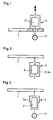
- FIGS. 1 and 7 show the principle of arrangements for damping vibrations.
- Fig. 7 the arrangement of Fig. 1 is shown on a larger scale and in section. 8 shows the characteristic curve for FIGS. 1 and 7.
- an elastic system main system
- a damper mass additional system
- a both resilient and damping element with 3, which is essentially an annular friction spring 3 '.
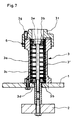
- the friction spring 3 'surrounded by a housing 3a is arranged on one side of the elastic system 1 and connected to the damper mass 2 located on the other side of the elastic system 1 via a pull and push rod 3c.
- the friction spring element 3 ' consists of outer rings and slotted inner rings, which each interact via conical contact surfaces.
- support plates 3d and 3e are provided, of which the lower (3d) in the plane of the drawing bears against the elastic system 1 and the upper (3e) against a base piece 3f of the housing 3a .
- bottom piece 3f and housing 3a are connected to one another by a thread, which also serves as an auxiliary device 6 for adjusting the pretension for the friction spring element 3 '.
- a screw 3g secures the base piece 3f against unintentional twisting.
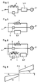
- the force F-path x diagram shown in FIG. 8 for the arrangement according to FIGS. 1 and 7 is symmetrical with regard to the tensile and compressive range.
- the load lines B and the relief lines E are each linear; both lines together give the specific non-linear characteristic of the friction spring element 3 '.
- the resilient and damping element 3 is suspended from the elastic system 1 according to FIG. 2, the housing 3a simultaneously forming the damper mass 2.
- the housing 3a consists of two telescopically guided housing parts.
- the damper mass 2 is also connected in this case in the pulling and pushing directions with the friction spring element 3 '.
- the damper mass 2 can be a rigid body or an elastic body that carries out relevant own movements even in the frequency range of interest.
Landscapes
- Engineering & Computer Science (AREA)
- General Engineering & Computer Science (AREA)
- Mechanical Engineering (AREA)
- Vibration Dampers (AREA)
- Vibration Prevention Devices (AREA)
- Springs (AREA)
Description
Der Erfindung betrifft eine Anordnung gemäß Oberbegriff des Auspruchs 1.The invention relates to an arrangement according to the preamble of
Elastische Systeme mit geringer Eigendämpfung - wie Antriebseinheiten, Rohrleitungen, Seile - werden beispielsweise durch Unwuchten, Kräfte aus Strömungen oder Seismik zu Schwingungen angeregt, die mit Hilfe dynamischer Schwingungsdämpfer zu beruhigen sind.Elastic systems with low internal damping - such as drive units, pipelines, ropes - are excited to vibrate, for example, by imbalance, forces from currents or seismics, which can be calmed with the help of dynamic vibration dampers.
Dem Fachmann sind dynamische Schwingungsdämpfer allgemein bekannt, die aus einer Dämpfermasse, axial belastbaren Schraubenfedern und parallel zu diesen angeordneten hydraulischen Dämpfungselementen bestehen, wobei die Schrauben federn und die Dämpfungselemente mit dem elastischen System und der Dämpfermasse verbunden sind. Bei solchen dynamischen Schwingungsdämpfern liegt ein Problem darin, daß die hydraulischen Dämpfungselemente nichtlineare Eigenschaften aufweisen, zusätzliche Federkräfte entwickeln und bei kleinen Wegen oder kleinen Schwinggeschwindigkeiten nicht wirkungsvoll arbeiten.Dynamic vibration dampers are generally known to the person skilled in the art, which consist of a damper mass, axially loadable coil springs and hydraulic damping elements arranged parallel to these, the screws springing and the damping elements being connected to the elastic system and the damper mass. A problem with such dynamic vibration dampers is that the hydraulic damping elements have non-linear properties, develop additional spring forces and do not work effectively with small travel or low vibration speeds.
Zum Stand der Technik gehören weiter dynamische Schwingungsdämpfer mit Gummielementen oder solche mit quer belastbaren Drahtseil-Schraubenfedern (DE-C-28 06 757), die jeweils sowohl federnde als auch dämpfende Wirkung haben. Als ein Nachteil dieser Schwingungsdämpfer wird angesehen, daß die maßgebenden Kennlinien nur mit einem erheblichen theoretischen Aufwand vorausberechnet werden können, so daß der praxisgerechte Einsatz, der eine entsprechende Dämpferauslegung erfordert, ohne versuchstechnischen Nachweis mit Unsicherheit behaftet ist. Außerdem ungünstig weisen Gummielemente ein frequenz- und temperaturabhängiges Verhalten auf.The prior art also includes dynamic vibration dampers with rubber elements or those with transversely loadable wire rope coil springs (DE-C-28 06 757), each of which has both a resilient and a damping effect. A disadvantage of these vibration dampers is that the decisive characteristic curves can only be calculated in advance with a considerable theoretical effort, so that the practical use, which requires a corresponding damper design, is subject to uncertainty without any technical evidence. In addition, rubber elements have a frequency and temperature-dependent behavior.
Der Erfindung liegt die Aufgabe zugrunde, eine Anordnung der gattungsgemäßen Art, wie sie aus der DE-C-2 806 757 bekannt ist, so zu verbessern, daß die vorstehend genannten Nachteile beseitigt sind.The invention has for its object to improve an arrangement of the generic type, as is known from DE-C-2 806 757, so that the disadvantages mentioned above are eliminated.
Diese Aufgabe wird erfindungsgemäß dadurch gelöst, daß als federndes und dämpfendes Element eine aus Außenringen und Innenringen gebildete Reibungsfeder vorgesehen ist, deren Ringe jeweils über konische Berührungsflächen zusammenwirken.This object is achieved in that a friction spring formed from outer rings and inner rings is provided as the resilient and damping element, the rings of which cooperate in each case via conical contact surfaces.
Durch beispielsweise die Dokumente GB-A-166 516, DE-C-1 455 252 und GB-A-315 941 sind aus Außenringen und Innenringen gebildete Reibungsfeder-Elemente bekannt, wobei diese Ringe über konische Berührungsflächen zusammenwirken. Solche Reibungsfeder-Elemente werden vor allem bei Zug- und Stoßvorrichtungen sowie Hülsenpuffern von Schienenfahrzeugen verwendet. Als federnde und schwingungsdämpfende Elemente eines dynamischen Schwingungsdämpfers sind Reibungsfeder-Elemente allerdings bisher nicht vorgesehen worden.Friction spring elements formed from outer rings and inner rings are known from documents GB-A-166 516, DE-C-1 455 252 and GB-A-315 941, for example, these rings interacting via conical contact surfaces. Friction spring elements of this type are used primarily in pulling and pushing devices and sleeve buffers in rail vehicles. So far, however, friction spring elements have not been provided as resilient and vibration-damping elements of a dynamic vibration damper.
Der Erfindungsgegenstand weist gegenüber bekannten Ausführungen vor allem folgende Vorteile auf:
- Durch die spezifischen nichtlinearen Eigenschaften des Reibungsfeder-Elements ist eine wesentlich größere Fehlertoleranz bei der Abstimmung des Systems als bei linearen beziehungsweise fast linearen Schwingungsdämpfern gegeben, d.h., Abweichungen von erwarteten Eigenfrequenzen und reduzierten Massen beziehungsweise Veränderungen von Eigenfrequenzen und reduzierten Massen durch betriebliche Bedingungen (beispielsweise Temperaturveränderungen, variable Massenbelegung) wirken sich in erheblich geringerem Maße dämpfungsmindernd aus als bei linearen Schwingungsdämpfern. Die spezifisch nichtlinearen Eigenschaften führen auch dazu, daß bei Systemen mit mehreren Eigenfrequenzen Schwingungen außerhalb der Abstimmungsfrequenz des Dämpfers wirksamer gedämpft werden als bei Linearen bzw. fast Linearen Schwingungsdämpfern.
- Das Systemverhalten ist durch diebereichsweise linearen Kennlinien des Reibungsfeder-Elements klar definiert und durch Einsatz axial geschlitzter und/oder geschlossener Ringe der Reibungsfeder sowie durch die Anzahl der Ringe festgelegt, so daß eine eindeutige Berechenbarkeit gegeben ist.
- Die Kennlinien sind unabhängig vom Schwingweg, von der Schwinggeschwindigkeit und von der Temperatur, bei sehr gutem Dauerschwingverhalten des Reibungsfeder-Elements.
- Due to the specific non-linear properties of the friction spring element, there is a much greater error tolerance when tuning the system than with linear or almost linear vibration dampers, i.e. deviations from expected natural frequencies and reduced masses or changes in natural frequencies and reduced masses due to operational conditions (e.g. temperature changes , variable mass allocation) have a significantly lower damping effect than with linear vibration dampers. The specific non-linear properties also lead to the fact that in systems with several natural frequencies, vibrations outside the tuning frequency of the damper are damped more effectively than with linear or almost linear vibration dampers.
- The system behavior is clearly defined by the linear characteristic curves of the friction spring element and by the use of axially slotted and / or closed rings of the friction spring and by the number of rings, so that there is a clear calculation.
- The characteristics are independent of the vibration path, the vibration speed and the temperature, with very good fatigue behavior of the friction spring element.
Um im Sinne einer Optimierung der Schwingungsdämpfung spezifische Eigenschaften des Hauptsystems gezielt berücksichtigen zu können, ist nach einer Ausgestaltung der Erfindung vorgesehen, da] parallel und/oder in Reihe zu dem Reibungsfeder-Element andere federnde und/oder dämpfende Bauteile angeordnet sind.In order to be able to specifically take into account specific properties of the main system in order to optimize the vibration damping, it is provided according to an embodiment of the invention that other resilient and / or damping components are arranged parallel and / or in series with the friction spring element.
Gemäß einer nächsten Ausgestaltung der Erfindung steht das Reibungsfeder-Element unter Vorspannung. Dadurch wird die in einigen Anwendungsfällen bestehende Forderung erfüllt, dem Hauptsystem unterhalb einer der Vorspannung entsprechenden Grenzbeschleunigung beziehungsweise Grenzverformung keine Zusatzdämpfung zuzuführen und/oder keine Frequenzverstimmung durch die elastischen Eigenschaften des Schwingungsdämpfers zu bewirken. Wegen der Vorspannung des Reibungsfeder-Elements kann weiter günstig bei der Identifikation eines Hauptsystems, das unterhalb der Grenzbeschleunigung nur massenmäßig beeinflußt wird, auch bei eingebautem Schwingungsdämpfer auf eine Blockierung des Elements verzichtet werden, wenn die Grenzbeschleunigung nicht überschritten wird.According to a next embodiment of the invention, the friction spring element is under prestress. In this way, the requirement existing in some applications is met that no additional damping is applied to the main system below a limit acceleration or limit deformation corresponding to the preload and / or no frequency detuning is caused by the elastic properties of the vibration damper. Because of the pretensioning of the friction spring element, it is also possible to dispense with blocking of the element if a main system, which is influenced only in mass below the limit acceleration, is inexpensive, even with a built-in vibration damper, if the limit acceleration is not exceeded.
Eine ergänzende Ausbildung der Erfindung liegt darin, daß die Vorspannung des Reibungsfeder-Elements mittels geeigneter Hilfseinrichtungen variabel einstellbar ist. Falls die Vorspannung für einen bestimmten Anwendungsfall, also einmalig oder selten einzustellen ist, empfiehlt sich als Hilfsmittel dazu eine einfache Schraubenanordnung. Es ist auch durchaus möglich, die Vorspannung während des Erregungsvorganges permanent einem jeweils gewünschten Dämpfungsverhalten anzupassen. Dafür kommen als Hilfsmittel aktive Regelungen in Betracht, wie Meßwertgeber, Mikroprozessor und Hydraulik.A supplementary embodiment of the invention is that the preload of the friction spring element can be variably adjusted by means of suitable auxiliary devices. If the preload is to be set for a specific application, i.e. once or rarely, a simple screw arrangement is recommended as an aid. It is also entirely possible to permanently adapt the preload to a desired damping behavior during the excitation process. Active controls such as sensors, microprocessors and hydraulics can be considered as aids.
Nach weiteren Ausführungsformen der Erfindung ist vorgesehen, daß das Reibungsfeder-Element in Zug- und Druckrichtung eine symmetrische Kennlinie oder eine asymmetrische Kennlinie aufweist, durch die es im letzteren Fall in Zugrichtung anders arbeitet als in Druckrichtung. Bei der im Grenzfall der Asymmetrie nur einseitigen Kennlinie werden zwischen dem Hauptsystem und der Dämpfermasse stoßförmige Kräfte hervorgerufen, durch die das Schwingungsverhalten in speziellen Anwendungsfällen günstig beeinflußbar ist.According to further embodiments of the invention, it is provided that the friction spring element has a symmetrical characteristic or an asymmetrical characteristic in the pulling and pushing direction, by means of which it works differently in the pulling direction than in the pushing direction in the latter case. In the case of the characteristic curve, which is only one-sided in the borderline case of asymmetry, shock-like forces are produced between the main system and the damper mass, by means of which the vibration behavior can be favorably influenced in special applications.
Eine bauliche Vereinfachung ist gemäß einer nächsten Ausgestaltung der Erfindung dadurch erzielbar, daß ein zum Reibungsfeder-Element gehörendes Gehäuse zumindest einen Teil der Dämpfermasse bildet.A structural simplification can be achieved according to a next embodiment of the invention in that a housing belonging to the friction spring element forms at least part of the damper mass.
Um Geräusche und Verschleiß so gering wie möglich zu halten, ist nach einer weiteren Ausführungsform der Erfindung vorgesehen, daß das Reibungsfeder-Element zum Verhindern metallischer Anschläge scheibenförmige elastische Schichten aufweist.In order to keep noise and wear as low as possible, it is provided according to a further embodiment of the invention that the friction spring element has disc-shaped elastic layers to prevent metallic stops.
Ausführungsbeispiele der Erfindung sind in der Zeichnung schematisch dargestellt und werden im folgenden näher beschrieben. Die Fig. 1 bis 6 zeigen jeweils das Prinzip von Anordnungen zum Dämpfen von Schwingungen. In Fig. 7 ist die Anordnung nach Fig. 1 im größeren Maßstab und im Schnitt gezeigt. Fig. 8 zeigt die Kennlinie zu Fig. 1 und 7.Embodiments of the invention are shown schematically in the drawing and are described in more detail below. 1 to 6 each show the principle of arrangements for damping vibrations. In Fig. 7 the arrangement of Fig. 1 is shown on a larger scale and in section. 8 shows the characteristic curve for FIGS. 1 and 7.
In allen Beispielen ist ein elastisches System (Hauptsystem) mit 1, eine Dämpfermasse (Zusatzsystem) mit 2 und ein sowohl federndes als auch dämpfendes Element mit 3 bezeichnet, wobei es sich im wesentlichen um eine ringförmige Reibungsfeder 3' handelt.In all examples, an elastic system (main system) with 1, a damper mass (additional system) with 2 and a both resilient and damping element with 3, which is essentially an annular friction spring 3 '.
Gemäß Fig. 1 und 7 ist die von einem Gehäuse 3a umgebene Reibungsfeder 3' auf einer Seite des elastischen Systems 1 angeordnet und über eine Zug- und Druckstange 3c mit der auf der anderen Seite des elastischen Systems 1 befindlichen Dämpfermasse 2 verbunden. Wie aus Fig. 7 näher ersichtlich, besteht das Reibungsfeder-Element 3' aus Außenringen und geschlitzten Innenringen, die jeweils über konische Berührungsflächen zusammenwirken. Zum Anlenken dieses Reibungsfeder-Elements 3' an die Zug- und Druckstange 3c sind Stützplatten 3d und 3e vorgesehen, von denen die in Zeichnungsebene untere (3d) gegen das elastische System 1 und die obere (3e) gegen ein Bodenstück 3f des Gehäuses 3a anliegt. Im Bereich der beiden vorgenannten Anlageflächen sowie zwischen dem Kopf der Zug- und Druckstange 3c und der oberen Stützplatte 3e befinden sich scheibenförmige elastische Schichten 3b, die metallische Anschläge verhindern. Bodenstück 3f und Gehäuse 3a sind durch ein Gewinde miteinander verbunden, das auch als Hilfseinrichtung 6 zum Einstellen der Vorspannung für das Reibungsfeder-Element 3' dient. Eine Schraube 3g sichert das Bodenstück 3f gegenüber einem ungewollten Verdrehen.According to FIGS. 1 and 7, the friction spring 3 'surrounded by a
Das in Fig. 8 gezeigte Kraft F - Weg x - Diagramm zu der Anordnung nach Fig. 1 und 7 ist bezüglich des Zug- und des Druckbereiches symmetrisch. Die Belastungslinien B und die Entlastungslinien E sind jeweils linear; beide Linien zusammen ergeben die spezifisch nichtlineare Kennlinie des Reibungsfeder-Elements 3'.The force F-path x diagram shown in FIG. 8 for the arrangement according to FIGS. 1 and 7 is symmetrical with regard to the tensile and compressive range. The load lines B and the relief lines E are each linear; both lines together give the specific non-linear characteristic of the friction spring element 3 '.
Unterschiedlich zu Fig. 1 ist gemäß Fig. 2 das federnde und dämpfende Element 3 am elastischen System 1 aufgehängt, wobei das Gehäuse 3a zugleich die Dämpfermasse 2 bildet. Bei der in Fig. 3 dargestellten Aufhängung des federnden und dämpfenden Elements 3 besteht das Gehäuse 3a aus zwei teleskopartig zueinander geführten Gehäuseteilen. Die Dämpfermasse 2 ist auch in diesem Fall in Zug- und in Druckrichtung mit dem Reibungsfeder-Element 3' verbunden.Different from FIG. 1, the resilient and damping
Je nach Anwendungsfall können in Kombination mit dem Reibungsfeder-Element 3' weitere solche Elemente 3', aber auch andere federnde Bauteile 4 und dämpfende Bauteile 5 vorgesehen werden. Gemäß Fig. 4 ist jeweils in Reihe zu dem Reibungsfeder-Element 3' ein anderes federndes Bauteil 4 und ein anderes dämpfendes Bauteil 5 angeordnet. Im Beispiel nach Fig. 5 arbeiten ein anderes federndes Bauteil 4 und ein anderes dämpfendes Bauteil 5 jeweils parallel zum Reibungsfeder-Element 3'. Gegenüber Fig. 5 ist nach Fig. 6 ein zusätzliches federndes Bauteil 4 und ein zusätzliches dämpfendes Bauteil 5 zu dem Reibungsfeder-Element 3' angeordnet. Die Darstellungen nach Fig. 4 bis 6 weisen im übrigen den Weg zu weiteren, nicht dargestellten Kombinationsmöglichkeiten, beispielsweise einer Reihen- oder Parallelanordnung von Reibungsfeder-Element 3' und nur einem anderen, entweder federnden oder dämpfenden Element 4 bzw. 5.Depending on the application, further such elements 3 ', but also other resilient components 4 and
Bei der Dämpfermasse 2 kann es sich um einen starren Körper oder um einen elastischen Körper handeln, der selbst im interessierenden Frequenzbereich relevante Eigenbewegungen ausführt.The
Claims (8)
- An arrangement for damping oscillations in resilient systems (1), essentially consisting of a device - having an additional body effective as a damping body (2) and at least one resilient damping member (3) - and the resilient system (1), the member (3) being connected to the resilient system (1) and to the damping body (2), characterised in that a friction spring (3') formed from external and internal rings is provided as the resilient damping member (3), and the rings thereof each co-operate over conical contact surfaces.
- An arrangement in accordance with claim 1, characterised in that other resilient and/or damping components (4, 5) are arranged in parallel and/or in series with the friction spring member (3').
- An arrangement in accordance with claim 1 or 2, characterised in that the friction spring member (3') is pre-stressed.
- An arrangement in accordance with claim 3, characterised in that the pre-stressing of the friction spring member (3') is variably adjustable by means of suitable additional devices (6).
- An arrangement in accordance with one of claims 1 to 4, characterised in that the friction spring member (3') has a symmetrical characteristic in the tension and compression directions.
- An arrangement in accordance with one of claims 1 to 4, characterised in that the friction spring member (3') has an asymmetrical characteristic, whereby it operates differently in the tension direction and in the compression direction.
- An arrangement in accordance with one of claims 1 to 6, characterised in that a casing (3a), associated with the friction spring member (3'), forms at least one part of the damping body (2).
- An arrangement in accordance with one of claims 1 to 7, characterised in that the friction spring member (3') has disc-shaped resilient layers (3b) to prevent impact between metal surfaces.
Applications Claiming Priority (2)
| Application Number | Priority Date | Filing Date | Title |
|---|---|---|---|
| DE3823207 | 1988-07-08 | ||
| DE3823207A DE3823207A1 (en) | 1988-07-08 | 1988-07-08 | DEVICE FOR DAMPING VIBRATIONS OF ELASTIC SYSTEMS |
Publications (3)
| Publication Number | Publication Date |
|---|---|
| EP0349978A2 EP0349978A2 (en) | 1990-01-10 |
| EP0349978A3 EP0349978A3 (en) | 1990-06-13 |
| EP0349978B1 true EP0349978B1 (en) | 1993-12-15 |
Family
ID=6358281
Family Applications (1)
| Application Number | Title | Priority Date | Filing Date |
|---|---|---|---|
| EP89112196A Expired - Lifetime EP0349978B1 (en) | 1988-07-08 | 1989-07-04 | Arrangement for damping oscillations in elastic systems |
Country Status (2)
| Country | Link |
|---|---|
| EP (1) | EP0349978B1 (en) |
| DE (2) | DE3823207A1 (en) |
Families Citing this family (3)
| Publication number | Priority date | Publication date | Assignee | Title |
|---|---|---|---|---|
| WO2015017792A1 (en) * | 2013-08-01 | 2015-02-05 | Lord Corporation | Method for suppression of resonant vibrations in subsea pipelines |
| CN113357302B (en) * | 2021-06-24 | 2024-12-20 | 中铁桥研科技有限公司 | A built-in damping vibration reduction device |
| CN115978118B (en) * | 2022-12-29 | 2023-08-29 | 南京工诺科技有限公司 | Linear high-rigidity wedge spring assembly for thimble |
Citations (1)
| Publication number | Priority date | Publication date | Assignee | Title |
|---|---|---|---|---|
| DE1455252C3 (en) * | 1962-05-23 | 1975-02-13 | Ringfeder Gmbh, 4150 Krefelduerdingen | Pulling and pushing device for central buffer couplings of rail vehicles |
Family Cites Families (9)
| Publication number | Priority date | Publication date | Assignee | Title |
|---|---|---|---|---|
| BE405526A (en) * | ||||
| DE358328C (en) * | 1920-07-13 | 1922-09-09 | Ernst Kreissig | feather |
| GB315941A (en) * | 1928-05-11 | 1929-07-25 | Fritz Steffen | Improvements in or relating to spring columns, buffers and like shock-absorbing or cushioning devices |
| US2519702A (en) * | 1946-09-24 | 1950-08-22 | Cecil S Robinson | Duplex spring absorption unit |
| DE864178C (en) * | 1949-09-03 | 1953-01-22 | Ferdinand Dr-Ing Marguerre | Device for reducing mechanical vibrations |
| US3856242A (en) * | 1973-03-29 | 1974-12-24 | Gen Electric | Mounting apparatus for a surge voltage arrester |
| DE2806757C3 (en) * | 1978-02-17 | 1981-11-05 | Kabe-Werk Lufttechnik Und Entstaubung Gmbh & Co Kg, 6370 Oberursel | Arrangement for damping vibrations on buildings |
| DE3139956A1 (en) * | 1981-10-08 | 1983-04-28 | Licentia Patent-Verwaltungs-Gmbh, 6000 Frankfurt | DAMPER FOR RECEIVING VIBRATIONS (VIBRATION DAMPER) BETWEEN THE FOUNDATION AND FOOT PART OF A DEVICE, IN PARTICULAR A HIGH VOLTAGE SWITCHING DEVICE TO BE SET UP IN EARTHQUAKE HAZARD |
| DE3713620C1 (en) * | 1987-04-23 | 1988-01-21 | Ringfeder Gmbh | Device for resiliently absorbing impact forces, in particular buffer for rail vehicles |
-
1988
- 1988-07-08 DE DE3823207A patent/DE3823207A1/en not_active Withdrawn
-
1989
- 1989-07-04 DE DE89112196T patent/DE58906412D1/en not_active Expired - Fee Related
- 1989-07-04 EP EP89112196A patent/EP0349978B1/en not_active Expired - Lifetime
Patent Citations (1)
| Publication number | Priority date | Publication date | Assignee | Title |
|---|---|---|---|---|
| DE1455252C3 (en) * | 1962-05-23 | 1975-02-13 | Ringfeder Gmbh, 4150 Krefelduerdingen | Pulling and pushing device for central buffer couplings of rail vehicles |
Non-Patent Citations (1)
| Title |
|---|
| G. Niemann, "Maschinenelemente", Band 1, 2. Auflage 1975, Seite 234 * |
Also Published As
| Publication number | Publication date |
|---|---|
| DE58906412D1 (en) | 1994-01-27 |
| EP0349978A3 (en) | 1990-06-13 |
| EP0349978A2 (en) | 1990-01-10 |
| DE3823207A1 (en) | 1990-01-11 |
Similar Documents
| Publication | Publication Date | Title |
|---|---|---|
| DE69032856T2 (en) | VIBRATION DAMPING SYSTEM | |
| EP2759736B1 (en) | Vibration insulator comprising a helical spring | |
| DE60031336T2 (en) | Vibration damping device and matching magnetic damping mechanism | |
| DE102017128230A1 (en) | Bearing device for a vibrating machine, vibrating machine and method for operating a vibrating machine | |
| EP1528281B1 (en) | Adaptive vibration damper | |
| DE3328362A1 (en) | FLEXIBLE DAMPED SHAFT BEARING ARRANGEMENT, ESPECIALLY FOR ELECTRICAL MACHINES | |
| DE102013101544A1 (en) | Vibration damper for damping vibrations of object, has damper mass guided to base in radial direction to axis by bending beams, where application units are provided on base, with which bending beams are applied with variable pressure force | |
| DE2035764A1 (en) | Vibration absorber with phase reversal | |
| EP0268734A1 (en) | Sound-damping soft mounting | |
| EP0349978B1 (en) | Arrangement for damping oscillations in elastic systems | |
| DE1805789A1 (en) | Non-linear spring system using permanent magnets | |
| EP1803963A1 (en) | Hybrid stiffness modul for vibration isolation | |
| WO2019076879A1 (en) | VIBRATION TILER, ESPECIALLY FOR A CONTROL CABINET | |
| EP0257349B1 (en) | Spring | |
| DE4313973A1 (en) | Active suspension of a mass, especially driver's cab suspension of a commercial vehicle | |
| DE3816033C2 (en) | ||
| DE102008052424B4 (en) | Vibrationstilgersystem | |
| EP0278323B1 (en) | Vibration damping element | |
| DE2632574C2 (en) | Device for damping vibrations on internal combustion engines | |
| DE202018102837U1 (en) | Vibration damper for damping tower harmonics | |
| DE4210598A1 (en) | Buckling spring | |
| DE69201124T2 (en) | Elastic suspension device with different stiffnesses for storing a device. | |
| DE2337431C3 (en) | Tonearm that is balanced with a multi-part counterweight and contains resilient weight coupling elements | |
| EP3818201B1 (en) | Carding element | |
| DE202015002359U1 (en) | vibration isolator |
Legal Events
| Date | Code | Title | Description |
|---|---|---|---|
| PUAI | Public reference made under article 153(3) epc to a published international application that has entered the european phase |
Free format text: ORIGINAL CODE: 0009012 |
|
| AK | Designated contracting states |
Kind code of ref document: A2 Designated state(s): CH DE FR GB IT LI NL |
|
| PUAL | Search report despatched |
Free format text: ORIGINAL CODE: 0009013 |
|
| AK | Designated contracting states |
Kind code of ref document: A3 Designated state(s): CH DE FR GB IT LI NL |
|
| 17P | Request for examination filed |
Effective date: 19900525 |
|
| 17Q | First examination report despatched |
Effective date: 19920210 |
|
| GRAA | (expected) grant |
Free format text: ORIGINAL CODE: 0009210 |
|
| AK | Designated contracting states |
Kind code of ref document: B1 Designated state(s): CH DE FR GB IT LI NL |
|
| ET | Fr: translation filed | ||
| REF | Corresponds to: |
Ref document number: 58906412 Country of ref document: DE Date of ref document: 19940127 |
|
| GBT | Gb: translation of ep patent filed (gb section 77(6)(a)/1977) |
Effective date: 19940104 |
|
| ITF | It: translation for a ep patent filed | ||
| PLBE | No opposition filed within time limit |
Free format text: ORIGINAL CODE: 0009261 |
|
| STAA | Information on the status of an ep patent application or granted ep patent |
Free format text: STATUS: NO OPPOSITION FILED WITHIN TIME LIMIT |
|
| 26N | No opposition filed | ||
| PGFP | Annual fee paid to national office [announced via postgrant information from national office to epo] |
Ref country code: FR Payment date: 19980611 Year of fee payment: 10 |
|
| PGFP | Annual fee paid to national office [announced via postgrant information from national office to epo] |
Ref country code: GB Payment date: 19980623 Year of fee payment: 10 |
|
| PGFP | Annual fee paid to national office [announced via postgrant information from national office to epo] |
Ref country code: NL Payment date: 19980629 Year of fee payment: 10 |
|
| PGFP | Annual fee paid to national office [announced via postgrant information from national office to epo] |
Ref country code: CH Payment date: 19980701 Year of fee payment: 10 |
|
| PG25 | Lapsed in a contracting state [announced via postgrant information from national office to epo] |
Ref country code: GB Free format text: LAPSE BECAUSE OF NON-PAYMENT OF DUE FEES Effective date: 19990704 |
|
| PG25 | Lapsed in a contracting state [announced via postgrant information from national office to epo] |
Ref country code: LI Free format text: LAPSE BECAUSE OF NON-PAYMENT OF DUE FEES Effective date: 19990731 Ref country code: FR Free format text: THE PATENT HAS BEEN ANNULLED BY A DECISION OF A NATIONAL AUTHORITY Effective date: 19990731 Ref country code: CH Free format text: LAPSE BECAUSE OF NON-PAYMENT OF DUE FEES Effective date: 19990731 |
|
| PG25 | Lapsed in a contracting state [announced via postgrant information from national office to epo] |
Ref country code: NL Free format text: LAPSE BECAUSE OF NON-PAYMENT OF DUE FEES Effective date: 20000201 |
|
| GBPC | Gb: european patent ceased through non-payment of renewal fee |
Effective date: 19990704 |
|
| REG | Reference to a national code |
Ref country code: CH Ref legal event code: PL |
|
| NLV4 | Nl: lapsed or anulled due to non-payment of the annual fee |
Effective date: 20000201 |
|
| REG | Reference to a national code |
Ref country code: FR Ref legal event code: ST |
|
| PGFP | Annual fee paid to national office [announced via postgrant information from national office to epo] |
Ref country code: DE Payment date: 20020619 Year of fee payment: 14 |
|
| PG25 | Lapsed in a contracting state [announced via postgrant information from national office to epo] |
Ref country code: DE Free format text: LAPSE BECAUSE OF NON-PAYMENT OF DUE FEES Effective date: 20040203 |
|
| PG25 | Lapsed in a contracting state [announced via postgrant information from national office to epo] |
Ref country code: IT Free format text: LAPSE BECAUSE OF NON-PAYMENT OF DUE FEES;WARNING: LAPSES OF ITALIAN PATENTS WITH EFFECTIVE DATE BEFORE 2007 MAY HAVE OCCURRED AT ANY TIME BEFORE 2007. THE CORRECT EFFECTIVE DATE MAY BE DIFFERENT FROM THE ONE RECORDED. Effective date: 20050704 |