EP0349969A2 - Mixing apparatus - Google Patents
Mixing apparatus Download PDFInfo
- Publication number
- EP0349969A2 EP0349969A2 EP89112154A EP89112154A EP0349969A2 EP 0349969 A2 EP0349969 A2 EP 0349969A2 EP 89112154 A EP89112154 A EP 89112154A EP 89112154 A EP89112154 A EP 89112154A EP 0349969 A2 EP0349969 A2 EP 0349969A2
- Authority
- EP
- European Patent Office
- Prior art keywords
- barrel
- barrel section
- fluid
- section
- locking
- Prior art date
- Legal status (The legal status is an assumption and is not a legal conclusion. Google has not performed a legal analysis and makes no representation as to the accuracy of the status listed.)
- Granted
Links
Images


Classifications
-
- B—PERFORMING OPERATIONS; TRANSPORTING
- B29—WORKING OF PLASTICS; WORKING OF SUBSTANCES IN A PLASTIC STATE IN GENERAL
- B29B—PREPARATION OR PRETREATMENT OF THE MATERIAL TO BE SHAPED; MAKING GRANULES OR PREFORMS; RECOVERY OF PLASTICS OR OTHER CONSTITUENTS OF WASTE MATERIAL CONTAINING PLASTICS
- B29B7/00—Mixing; Kneading
- B29B7/002—Methods
- B29B7/007—Methods for continuous mixing
-
- B—PERFORMING OPERATIONS; TRANSPORTING
- B01—PHYSICAL OR CHEMICAL PROCESSES OR APPARATUS IN GENERAL
- B01F—MIXING, e.g. DISSOLVING, EMULSIFYING OR DISPERSING
- B01F35/00—Accessories for mixers; Auxiliary operations or auxiliary devices; Parts or details of general application
- B01F35/10—Maintenance of mixers
Definitions
- This invention relates to apparatus for continuous mixing. More particularly, this invention relates to apparatus for continuous mixing where the material being mixed is unstable such as explosives and the like.
- Apparatus for continuously mixing, blending and/or extruding have been developed over the years and utilized in many continuous processing systems. Such apparatus have been used in such diverse applications as polymer manufacture, compounding and finishing systems, rubber mixing, grafting and degasing, food processing and hazardous waste solidification. Other applications have included fossil fuel pelletizing and agglomeration, and the continuous production of adhesives, powder coatings, catalysts and the like.
- PBX plastic-bonded explosives
- some mixers are disassembled for cleaning by removing the screws from the barrel.
- Others have axially split barrels with the sections being hinged together so as to rotatably swing away from the screws. Again, while acceptable for some materials, such structures are not desirable for materials such as explosives. Removal of the screws from the barrel often is accompanied by the screws accidentally striking the barrel surface. Where the mixer has been used to mix explosives there is a residuum of explosive material which may well be detonated by the striking of the screws against the barrel.
- hinged barrel sections they are subject to having explosive material find its way into the hinge mechanisms which, in response to rotation of the hinges, may detonate.
- Another object of the present invention is to provide an apparatus for continuous mixing which minimizes the likelihood of the occurrence of surface-to-surface moving contact between components of the apparatus.
- Yet an additional object of the present invention is to provide a continuous mixing apparatus wherein the mixing screws are supported for rotation by bearings which are remote from exposure to the product being mixed.
- a further object of the present invention is to provide an apparatus for continuous blending in which the barrel of the process section may be separated from the mixing screws selectively or automatically in response to the occurrence of pre-determined process conditions.
- Still another object of the present invention is to provide an apparatus for continuous blending where the barrel may be separated from the mixing screws for service and cleaning without axial removal of the screws and without the use of hinges or other structures which create opportunities for the generation of high shear stresses in materials being mixed with the attendant danger of catastrophic results.
- a mixing apparatus may include a driving means, a processing section having first and second barrel sections, a mixing screw operatively connected to the driving means and means for displacing the first and second barrel sections between a closed position and an open position without relative movement between any surface of said first and second barrel sections which are in surface-to-surface contact.
- FIGS. 1-3 there is shown an apparatus for continuous mixing structured in accordance with the present invention and designated generally by reference numeral 10.
- apparatus 10 is depicted generally and the figures do not show details of the device such as gauges, hydraulic lines, switches and the like, all of which may be chosen from the many which are commercially available and the operation of which is generally known to those skilled in these arts.
- the hydraulic system for operating apparatus 10 which forms a part of the invention, is discussed in detail hereinafter. What is depicted, however, when considered in light of the following detailed description, clearly is sufficient to permit those having ordinary skill in these arts to make and use continuous mixing apparatus incorporating the features of this invention.
- apparatus 10 can be seen to include a base frame 12 which is suitably supported by a floor 14 of adequate load-bearing capacity.
- Base frame 12 serves as a rigid support for a motor 16, a reduction and distribution gear mechanism or gearbox 18 and an inboard bearing support member or lantern 20.
- Motor 16 may be a standard variable speed motor (frequency-controlled AC, rectifier-controlled DC or a hydraulic motor and drive) mounted and coupled in any of the methods well known in these arts.
- the output shaft 22 of motor drive 16 is suitably coupled to the input shaft 24 of gearbox 18 which establishes a preselected ratio of rotational speed between the motor 16 and a pair of output shafts 28 and 30.
- Linear loads generated through shafts 28 and 30 are carried by a thrust bearing 26 mounted on gearbox 18.
- the output shafts 28 and 30 of gearbox 18 are coupled, e.g., by splining, to the drive ends of a pair of mixing screws 32 and 34, respectively.
- Mixing screws 32 and 34 are rotatably supported by suitable bearings mounted in lantern 20.
- the bearings may be selected from any of the many known to those skilled in these arts. However, in the embodiment shown in FIGS. 1-3, mixing screws 32 and 34 are supported for rotation only at bearing support member 20 with the major portions of the lengths of the shafts being cantilevered within the lines of a process section 36 as is described below. Accordingly, the bearings mounted in lantern 20 must be suitable for that purpose.
- Bearing support member 20 is mounted on and rigidly secured to baseframe 12. Further, bearing support member 20 is rigidly secured to the casing of gearbox 18 by a plurality of rods 38. Integral with bearing support member 20 and disposed at its upper end is a first stop means 40, the purpose of which is discussed below. First stop means 40 extends toward and over process section 36.
- Process section 36 comprises an upper barrel section 42 and a lower barrel section 44. Barrel sections 42 and 44 are supported above baseframe 12 by four spring assemblies 46 (two shown), the detailed structure of which is disclosed below.
- the lower or mating surface of upper barrel section 42 is in surface-to-surface engagement with the upper or mating surface of lower barrel section 44.
- the plane defined by this surface-to-surface or mating engagement is generally parallel to the surface of floor 14.
- the lower surface of upper barrel section 42 and the upper surface of lower barrel section 44 are each machined to define intersecting cylindrical surfaces that form longitudinally extending bores.
- the hemispherical bores in upper barrel section 42 cooperate with the bores in lower section 44 to define longitudinally extending, overlapping parallel bores 50 and 52.
- bore 50 receives mixing screw 34 coaxially therein
- bore 52 receives mixing screw 32 coaxially therein.
- Mixing screws 32, 34 extend into and through bores 52 and 50 from their ends adjacent lantern 20 to a point just short of the opposite ends of bores 50 and 52.
- the mixing screws 32 and 34 extend completely through bores 52 and 50 respectively to be received in support bearings located at a position spaced from the end of process section 36. It should be noted that at no time during the operation of apparatus 10 do mixing screws 32 and 34 come into contact with the material of upper barrel section 43 or lower barrel section 44. Further, there is never any relative movement between upper barrel section 42 and lower barrel section 44 when their respective lower and upper surfaces are engaged. As a result, the operation of apparatus 10 does not involve any relative movement between any surface of the upper and lower barrel sections which are in surface-to surface contact. This is most importantly so in areas where materials being processed are present. This is particularly important where the materials being processed are unstable such as explosives and the like.
- End frame 54 Rigidly secured to the right end of baseframe 12 as seen in Fig. 1 is end frame 54.
- End frame 54 includes a bed plate 56 which is rigidly secured to baseframe 12, a vertical support plate 58 which is secured to bed plate 56 and extends upwardly to a position above process section 36, and a horizontal support plate 60 which is disposed above process section 36.
- Vertical support plate 58 is rigidly secured to bed plate 56 and retained in vertical position by a pair of generally triangular gusset plate 62.
- the lower surface 64 of horizontal support plate 60 is coplanar with the lower surface 41 of first stop means 40 on lantern 20.
- support plate 66 Suspended from the lower surface 64 of horizontal support plate 60 is support plate 66.
- support plate 66 supports a pair of locating pins 68 which cooperate with recesses found in the lower and upper surfaces of upper and lower barrel sections, respectively, to properly locate and portion the respective barrel sections during operation.
- locating pins 39 which are disposed in lantern 20 serve the identical purpose with respect to ends of upper and lower barrel section 42, 44 adjacent to the bearing support section. The use of such pins as locating devices and the particulars of their construction are well known to those skilled in these arts.
- locating pins 39 and 68 also serve as support means for supporting upper barrel section 42 and its associated hydraulic cylinder assemblies. The locating pins also serve as reaction means against which lower barrel section 44 bears during the closing cycle of process section 36.
- an opening 70 Formed through the upper surface of upper barrel section 42 is an opening 70 which defines the feed port for introducing materials to be processed into bores 50 and 52 of process section 36. It will be recognized that more than one feed port may be utilized. Further, known devices such as injection means can be utilized to introduce other materials to be processed.
- processed materials are discharged through the open ends of bores 50, 52 adjacent end frame 54.
- Processed materials so discharged may fall into a container, fall into a conveyor belt or otherwise be handled based upon the requirements of the material being handled and the end product desired.
- a die plate may be mounted on the end of process section 36 such that materials discharging from bores 50, 52 can be passed therethrough and shaped, separated or otherwise formed based upon the particular configuration of the die plate. Utilization of such die plates is well known to those having skills in these arts.
- each spring assembly 46 can be seen to include a lower mounting block 74, an upper mounting block 76 and a spring 78 disposed between the two mounting blocks 74, 76.
- lower mounting block 74 is a generally square member (in plan view) having an axial opening therethrough defined by a bore 80, an upper counterbase 81 and a lower counterbase 82. Also found in lower mounting block 74 are a plurality of throughbores 84 (only one shown, FIG. 5) which are adapted to receive therein machine bolts 86 which threadidly engage tapped bores in baseframe 12 to rigidly secure the lower mounting block 74 to baseframe 12. Similarly, there are formed in each lower mounting block 74 at least two throughbores 88 which are utilized in conjunction with guide pins 89 to accurately position lower mounting block 74 with respect to baseframe 12 in a manner well known to those skilled in these arts.
- a machine bolt 90 which is threadedly received within a tapped bore 91 formed in spring rod 92.
- Rod 92 is slideably received within the upper counterbore 81 of lower mounting block 74 and extends upwardly out of block 74 to be slideably received within upper mounting block 76.
- upper mounting block 76 is a generally square member (in plan view) having an axial bore 94 extending upwardly through a portion of its depth. Formed in the lower end of axial bore 94 is a counterbore 96 which is sized to receive therein a sleeve bearing 97.
- the inside diameter of sleeve bearing 97 is substantially equal to the diameter of bore 94 and the outside diameter of spring rod 92.
- spring rod 92 is suitably slideably received within bearing 97 and bore 94 depending upon the relative vertical positioning of upper mounting block 76 with respect to lower mounting block 74.
- a cylindrical collar 99 Secured to the upper surface of lower mounting block 74 is a cylindrical collar 99 which, with an annular channel 100 formed in the upper end of lower mounting block 74, cooperates to receive and retain the lower end of spring 78.
- upper mounting block 76 Secured to the lower end of upper mounting block 76 is a cylindrical collar 102 which cooperates with an annular bore 103 formed in the lower surface of upper mounting block 76 to receive and retain the upper end of spring 78.
- upper mounting block 76 Also formed in upper mounting block 76 are at least two throughbores 104 (one shown) which are adapted to receive guide pins 106 for locating and positioning the upper mounting block 76 with respect to lower barrel section 44 in the manner well known to those skilled in these arts.
- hydraulic cylinder assembly 48 can be seen to consist of a fluid cylinder 108 reciprocally received within which is a piston 110. Cylinder 108 cooperates with piston 110 to define an upper fluid chamber 112 and a lower fluid chamber 114. It will be recognized by those skilled in these arts that the volumes of chambers 112 and 114 will vary depending upon the vertical position of piston 110 within cylinder 108.
- Upper fluid chamber 112 is in fluid communication with the hydraulic control system of apparatus 10 through a hydraulic fluid line 116.
- lower fluid chamber 114 is in fluid communication with the hydraulic control system of apparatus 10 through a hydraulic fluid line 118.
- Fluid cylinder 108 is rigidly secured to a plate 120 in which are formed a plurality of bores 122. Bores 122 are adapted to slidably receive therethrough a plurality of tie-rods 124 which extend through bores 126 formed in lower barrel section 44 and which are threadedly received within tapped bores 128 formed in upper barrel section 42. The lower ends of tie rods 124 are threaded to receive nuts 130 thereon so as to rigidly secure the tie rods with respect to plate 120 and cylinder 108. Thus, through tie rods 124, fluid cylinder 108 and upper barrel section 42 are rigidly locked together as a single unit.
- piston 110 is reciprocally mounted within cylinder 108.
- piston rod 132 Secured to or integral with piston 110 is piston rod 132 which extends upwardly out of upper fluid chamber 112.
- the upper end of rod 132 is provided with a tapped bore 134 within which is received a threaded coupling screw 136.
- Coupling screw 136 is received within the central bore 138 of a mounting plate 140 which is rigidly secured to the lower surface of lower barrel section 44 by machine screws 142.
- rod 132 is secured to lower barrel section 44 by causing coupling screw 136 to be threaded into tapped bore 134 while the screw is received within central bore 138 of mounting plate 140.
- coupling screw 136 has been properly threaded into rod 132, a pair of metal dowels 144 are inserted through openings in mounting plate 140 such as to cooperate with the head 146 of coupling screw 136 to preclude removal of the coupling screw 136 from the mounting plate 140.
- piston rod 132 is rigidly secured to the lower barrel section 44.
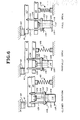
- FIGURE 6 schematically shows the three basic operational positions of the upper and lower barrel sections 42, 44 between fully closed position and fully open position.
- fluid cylinder 108 is rigidly secured to upper barrel section 42 through tie-rods 124, upward displacement of fluid cylinder 108 causes a corresponding upward displacement of upper barrel section 42 out of supporting contact with beating pins 39, 68.
- the upward displacement of upper barrel section 42 continues until its upper surface makes substantially simultaneous contact with the lower surface 41 of first stop means 40 and the lower surface 64 of horizontal support plate 60 (FIG. 1). The position is shown schematically as the "partially open" position of FIG. 6.
- the hydraulic system for operating apparatus 10 may be one designed using known hydraulic techniques.
- upper and lower barrel sections 42, 44 may be provided with fluid passages for circulating cooling or heating fluids to control the temperature of processes being performed.
- Sensors may be provided to measure process pressures and temperatures at various points in the process sections. All of such sensors are well recognized by those skilled in these arts to be usable and available.
- An additional unique feature of the present invention is the provision of locking means for locking piston rods 132 of the hydraulic cylinder assemblies 48 in a particular desired position.
- FIGURES 7 and 8 depict one of hydraulic cylinder assemblies 48, partly in section, showing locking structure for retaining the apparatus in the closed or operational position, i.e. the position which corresponds to that shown in FIG. 6 "Closed Position.” It will also be recognized by those skilled in these acts that substantially identical locking structures may be utilized to retain the apparatus in the "Open Position" as shown in FIG. 7.
- fluid cylinder 108 as designated in FIG. 6 can be seen to include a lower cylinder head 152 having a bore 154 within which is slidably received the lower end of a cylinder body 156.
- Cylinder body 156 is externally threaded adjacent its lower end for threadedly receiving a lower retaining ring 158.
- a plurality of axially extending bores 159 are found through retaining ring 158 to accomodate the passage therethrough of machine screws 160 which are threadedly received in tapped bores 161 formed in lower head 152.
- the inner surface of bore 154 is relieved to define an annular channel for receiving an O-ring seal 162 which is in surface-to-surface engagement until the outer surface of cylinder body 156 so as to provide a fluid tight seal between lower cylinder head 152 and cylinder body 156.
- the upper end of cylinder body 156 is also externally threaded for receiving an upper retaining ring 164.
- Formed in upper retaining ring 164 is a first axially extending bore 166 which cooperates with the inner surface of cylinder body 156 to define the upper portion of upper fluid chamber 112.
- Also formed in upper retaining ring 164 is a second axially extending bore 168 which is sized to permit the sliding passage therethrough of piston rod 132.
- Hydraulic fluid may pass into and from lower fluid chamber 114 through a radially extending passage 170 formed in lower head 152. Similarly, hydraulic fluid may pass into and from upper fluid chamber 112 through a radially extending passage 172 found in upper retaining ring 164. Also formed in upper retaining ring 164 is an axially extending passage 174 which permits flow of hydraulic fluid into and out of upper fluid chamber 112 from above retaining ring 164 as is discussed below.
- An O-ring seal 176 is provided in a suitable channel found in the inner surface of upper retaining ring 164 to preclude leakage of hydraulic fluid outwardly from upper fluid chamber 112 between the upper outer surface of cylinder body 156 and the inner surface of upper retaining ring 164.
- upper cylinder body 178 Disposed above upper retaining ring 164 is an upper cylinder body 178 in which are formed an axially extending bore 179, an upper axially extending bore 179, an upper axially extending counterbore 180 and a lower axially extending counterbore 181.
- upper head 182 Disposed above upper cylinder body 178 is an upper head 182 which is rigidly secured to upper cylinder body 178 and upper retaining ring 164 by a plurality of machine screws 184 (one shown) which extend through radially space axially extending bores 185 and 186 formed in upper head 182 and upper cylinder body 178, respectively, and are threadedly received within tapped bores 187 found in upper retaining ring 164.
- collar 188 Mounted within upper cylinder body 178 is a collar 188 the lower surface of which rests on the upper surface of upper retaining ring 164 and the outer surface of which is received within the channel defined by lower counterbore 181 so as to be firmly retained in position.
- Collar 188 is provided with an axial throughbore 190 which is sized to slidably receive piston rod 132 therethrough.
- upper head 182 is provided with an axial throughbore 192 which is sized to slidably receive piston rod 132 therethrough.
- Piston 194 separates the fluid chamber into an upper portion 195 and a lower portion 196. Passage of hydraulic fluid between upper cylinder portion 195 and lower cylinder portion 196 as well as out of the upper and lower cylinder portions is precluded with suitably positioned O-rings in the well known manner.
- Upper cylinder portion 195 is in hydraulic fluid communication with lower fluid chamber 114 through a fluid passage 198 formed in upper head 182 and suitable hydraulic piping (not shown).
- Lower cylinder portion 196 is in hydraulic fluid communication with upper fluid chamber 112 through passage 174 in upper retaining ring 164 and a coaxial passage 199 formed in collar 188.
- the lower surface of free-floating piston 194 is machined to define a camming surface which cooperates with the upper surface of a lock ring 200 to selectively lock or unlock the piston rod 132 in response to particular hydraulic conditions as is discussed below.
- Lock ring 200 may be a split ring structure which may be spread to accomodate the passage therethrough of piston rod 132 and which may be compressed to be received within an annular channel 202 formed in the surface of piston rod 132.
- the upper surface of lock ring 200 is tapered to correspond to the frusto-conical upper surface of channel 202.
- piston 110 is at the bottom of cylinder body 156 and the annular channel 202 of piston rod 132 is disposed within upper fluid chamber 112.
- free floating piston 194 is at its uppermost position and lock ring 200 is spread to permit the slidable passage therethrough of piston rod 132.
- pressurized hydraulic fluid is introduced into lower fluid chamber 114 and upper portion 195 through passages 170 and 198 respectively.
- Introduction of fluid in this manner initially causes piston 110 to be displaced upwardly and tends to push free floating piston 194 downwardly.
- piston 110 and therewith piston rod 132 are displaced upwardly without any movement of free floating piston 194 until the upper surface of annular channel 202 is adjacent the upper surface of lock ring 200.
- the lock ring may be compressed so as to be received within annular channel 202. This compression occurs by the displacement of free floating piston 194 downwardly such as to cam the lock ring into compressed position within channel 202.
- piston rod 132 With the lock ring 200 in this position, piston rod 132 is precluded from further axial movement. Further, so long as an excess of hydraulic pressure is maintained in upper portion 195, the lock ring will remain in the compressed, locking position.
- the above described structure thus provides a locking means which insures retention of the barrel sections in closed position so long as the correct hydraulic pressure relationships are maintained.
- Similar locking means may also be provided to retain this barrel section in open position. This may be beneficial as a safety measure to preclude closing of this apparatus during maintenance.
Landscapes
- Engineering & Computer Science (AREA)
- Mechanical Engineering (AREA)
- Chemical & Material Sciences (AREA)
- Chemical Kinetics & Catalysis (AREA)
- Processing And Handling Of Plastics And Other Materials For Molding In General (AREA)
- Mixers With Rotating Receptacles And Mixers With Vibration Mechanisms (AREA)
- Mixers Of The Rotary Stirring Type (AREA)
- Physical Or Chemical Processes And Apparatus (AREA)
Abstract
Description
- This invention relates to apparatus for continuous mixing. More particularly, this invention relates to apparatus for continuous mixing where the material being mixed is unstable such as explosives and the like.
- Apparatus for continuously mixing, blending and/or extruding have been developed over the years and utilized in many continuous processing systems. Such apparatus have been used in such diverse applications as polymer manufacture, compounding and finishing systems, rubber mixing, grafting and degasing, food processing and hazardous waste solidification. Other applications have included fossil fuel pelletizing and agglomeration, and the continuous production of adhesives, powder coatings, catalysts and the like.
- A particular challenge to those concerned with the design and manufacture of continuous mixing equipment is the challenge presented by the mixing of unstable materials such as explosives. For example, the manufacture of plastic-bonded explosives (PBX) involves the mixing of a liquid polyester matrix with explosive material in pellet or granular form to provide a homogeneously mixed product. There must be a consistent dispersion of the explosive material in the matrix and no reduction in the explosive grain size. In achieving an acceptable product, care must be taken not to cause shear stresses in the explosive material beyond defined limits because exceeding such limits may well result in detonation of the explosive material with catastrophic results.
- Known continuous mixing equipment is not particularly well suited for these applications. They operate based upon pressure generation, mixing and kneading to create desired shear and mixing intensities. There are structured relationships in the equipment such as at hinges and bearings where high shear forces may be exerted in the product being processed, which forces are unacceptable in handling explosives and other unstable materials. Very specific problems include the inability to quickly open the process section so as to avoid pressure build-up or excessively high temperatures, as well as difficulty in cleaning the equipment, particularly the bearings and hinges.
- In most known continuous mixers, the bearings which support the mixing screws for rotation are mounted on or integral with the barrel structure. As a result, product being mixed often gets into the moving bearing elements. Although this may not be a problem for mixing some materials, this is a very definite problem for materials such as explosives because any explosive material which enters the bearing and becomes subject to the moving parts may experience shear stresses which exceed the explosive limit with predictable and catastrophic results.
- With regard to cleaning, some mixers are disassembled for cleaning by removing the screws from the barrel. Others have axially split barrels with the sections being hinged together so as to rotatably swing away from the screws. Again, while acceptable for some materials, such structures are not desirable for materials such as explosives. Removal of the screws from the barrel often is accompanied by the screws accidentally striking the barrel surface. Where the mixer has been used to mix explosives there is a residuum of explosive material which may well be detonated by the striking of the screws against the barrel. As to hinged barrel sections, they are subject to having explosive material find its way into the hinge mechanisms which, in response to rotation of the hinges, may detonate.
- Another problem with other known mixers is that the flow-path of the material through the apparatus is such that dead spots are formed, i.e., spots where there is no continuous movement thus increasing the residence time of the material. Increased residence time is unacceptable as it increases the amount of energy added to the material which may lead to degradation and detonation.
- For the foregoing reasons, most mixing of explosive and otherwise unstable materials occurs by batch mixing. The products are mixed in batches ranging from five to ten thousand pounds per batch. This, of course, is a long and tedious process and far inferior to continuous mixing.
- It is an object of the present invention, therefore, to provide an apparatus for continuous mixing which is uniquely useful for the mixing of explosives.
- Another object of the present invention is to provide an apparatus for continuous mixing which minimizes the likelihood of the occurrence of surface-to-surface moving contact between components of the apparatus.
- Yet an additional object of the present invention is to provide a continuous mixing apparatus wherein the mixing screws are supported for rotation by bearings which are remote from exposure to the product being mixed.
- A further object of the present invention is to provide an apparatus for continuous blending in which the barrel of the process section may be separated from the mixing screws selectively or automatically in response to the occurrence of pre-determined process conditions.
- Still another object of the present invention is to provide an apparatus for continuous blending where the barrel may be separated from the mixing screws for service and cleaning without axial removal of the screws and without the use of hinges or other structures which create opportunities for the generation of high shear stresses in materials being mixed with the attendant danger of catastrophic results.
- These objects and other objects not enumerated are achieved by a mixing apparatus according to the present invention, an embodiment of which may include a driving means, a processing section having first and second barrel sections, a mixing screw operatively connected to the driving means and means for displacing the first and second barrel sections between a closed position and an open position without relative movement between any surface of said first and second barrel sections which are in surface-to-surface contact.
- It is not necessary, that all said objects are achieved by the features of claim 1.
- A more complete understanding of the present invention may be had from the following detailed description of a preferred embodiment, particularly when read in the light of the accompanying drawings wherein:
- FIGURE 1 is an elevational view of a continuous mixer according to the present invention;
- FIGURE 2 is a plan view of the mixer of FIGURE 1;
- FIGURE 3 is an end-view of the barrel end of the mixer of FIGURE 1;
- FIGURE 4 is a partial elevational view, partly in cross-section, of the apparatus of FIGURE 1;
- FIGURE 5 is a cross-sectional elevational view through the plane 5-5 of FIGURE 4;
- FIGURE 6 is a schematic view of a portion of the apparatus of FIGURE 1 showing relative positions of the apparatus of various operational conditions;
- FIGURE 7 is an elevational view, partly in section showing a locking means for the present invention in the unlocked position; and
- FIGURE 8 is a view similar to FIGURE 7 showing a locking means for the present invention in the locked position.
- Referring, therefore, to the drawings, and in particular to FIGS. 1-3, there is shown an apparatus for continuous mixing structured in accordance with the present invention and designated generally by
reference numeral 10. As will be recognized by those skilled in these arts,apparatus 10 is depicted generally and the figures do not show details of the device such as gauges, hydraulic lines, switches and the like, all of which may be chosen from the many which are commercially available and the operation of which is generally known to those skilled in these arts. Further, the hydraulic system foroperating apparatus 10, which forms a part of the invention, is discussed in detail hereinafter. What is depicted, however, when considered in light of the following detailed description, clearly is sufficient to permit those having ordinary skill in these arts to make and use continuous mixing apparatus incorporating the features of this invention. - Thus,
apparatus 10 can be seen to include abase frame 12 which is suitably supported by afloor 14 of adequate load-bearing capacity.Base frame 12 serves as a rigid support for amotor 16, a reduction and distribution gear mechanism orgearbox 18 and an inboard bearing support member orlantern 20.Motor 16 may be a standard variable speed motor (frequency-controlled AC, rectifier-controlled DC or a hydraulic motor and drive) mounted and coupled in any of the methods well known in these arts. - The
output shaft 22 ofmotor drive 16 is suitably coupled to theinput shaft 24 ofgearbox 18 which establishes a preselected ratio of rotational speed between themotor 16 and a pair ofoutput shafts shafts gearbox 18. - The
output shafts gearbox 18 are coupled, e.g., by splining, to the drive ends of a pair ofmixing screws - Mixing
screws lantern 20. The bearings may be selected from any of the many known to those skilled in these arts. However, in the embodiment shown in FIGS. 1-3, mixingscrews bearing support member 20 with the major portions of the lengths of the shafts being cantilevered within the lines of aprocess section 36 as is described below. Accordingly, the bearings mounted inlantern 20 must be suitable for that purpose. -
Bearing support member 20 is mounted on and rigidly secured tobaseframe 12. Further, bearingsupport member 20 is rigidly secured to the casing ofgearbox 18 by a plurality ofrods 38. Integral withbearing support member 20 and disposed at its upper end is a first stop means 40, the purpose of which is discussed below. First stop means 40 extends toward and overprocess section 36. - Rigidly secured within
lantern 20 are a pair of locatingpins 39 which extend into suitable bores in theprocess section 36, the axes of which bores are coplanar with the axes of mixingscrews -
Process section 36 comprises anupper barrel section 42 and alower barrel section 44.Barrel sections baseframe 12 by four spring assemblies 46 (two shown), the detailed structure of which is disclosed below. Whenprocess section 36 is in operational configuration, the lower or mating surface ofupper barrel section 42 is in surface-to-surface engagement with the upper or mating surface oflower barrel section 44. The plane defined by this surface-to-surface or mating engagement is generally parallel to the surface offloor 14. When it is desired or required to separateupper barrel section 42 fromlower barrel section 44, e.g., for cleaning or to avoid build-up of unacceptable or potentially catastrophic pressures and/or temperatures within the process section, separation of thebarrel sections Hydraulic cylinder assemblies 48 are secured to and supported by said first barrel section. - The lower surface of
upper barrel section 42 and the upper surface oflower barrel section 44 are each machined to define intersecting cylindrical surfaces that form longitudinally extending bores. Thus, when theprocess section 36 is in operational configuration, as is shown in Figs. 1-3, the hemispherical bores inupper barrel section 42 cooperate with the bores inlower section 44 to define longitudinally extending, overlapping parallel bores 50 and 52. In this regard, bore 50 receives mixingscrew 34 coaxially therein and bore 52 receives mixingscrew 32 coaxially therein. Mixing screws 32, 34 extend into and throughbores adjacent lantern 20 to a point just short of the opposite ends ofbores bores process section 36. It should be noted that at no time during the operation ofapparatus 10 do mixingscrews upper barrel section 43 orlower barrel section 44. Further, there is never any relative movement betweenupper barrel section 42 andlower barrel section 44 when their respective lower and upper surfaces are engaged. As a result, the operation ofapparatus 10 does not involve any relative movement between any surface of the upper and lower barrel sections which are in surface-to surface contact. This is most importantly so in areas where materials being processed are present. This is particularly important where the materials being processed are unstable such as explosives and the like. - Rigidly secured to the right end of
baseframe 12 as seen in Fig. 1 isend frame 54.End frame 54 includes abed plate 56 which is rigidly secured tobaseframe 12, avertical support plate 58 which is secured tobed plate 56 and extends upwardly to a position aboveprocess section 36, and ahorizontal support plate 60 which is disposed aboveprocess section 36.Vertical support plate 58 is rigidly secured tobed plate 56 and retained in vertical position by a pair of generallytriangular gusset plate 62. For purposes that are discussed below in detail, thelower surface 64 ofhorizontal support plate 60 is coplanar with thelower surface 41 of first stop means 40 onlantern 20. Suspended from thelower surface 64 ofhorizontal support plate 60 issupport plate 66. In the embodiment shown,support plate 66 supports a pair of locatingpins 68 which cooperate with recesses found in the lower and upper surfaces of upper and lower barrel sections, respectively, to properly locate and portion the respective barrel sections during operation. In this regard, locatingpins 39 which are disposed inlantern 20 serve the identical purpose with respect to ends of upper andlower barrel section apparatus 10, however, locatingpins upper barrel section 42 and its associated hydraulic cylinder assemblies. The locating pins also serve as reaction means against whichlower barrel section 44 bears during the closing cycle ofprocess section 36. - Formed through the upper surface of
upper barrel section 42 is anopening 70 which defines the feed port for introducing materials to be processed intobores process section 36. It will be recognized that more than one feed port may be utilized. Further, known devices such as injection means can be utilized to introduce other materials to be processed. - In the embodiment shown, processed materials are discharged through the open ends of
bores adjacent end frame 54. Processed materials so discharged may fall into a container, fall into a conveyor belt or otherwise be handled based upon the requirements of the material being handled and the end product desired. It will also be recognized by those skilled in these arts that a die plate may be mounted on the end ofprocess section 36 such that materials discharging frombores - As noted above, the upper and
lower barrel sections process section 36 are supported abovebaseframe 12 by a plurality ofspring assemblies 46. The structural specifics ofspring assembly 46 are disclosed hereinafter with particular reference to FIGURES 4 and 5. Thus, eachspring assembly 46 can be seen to include alower mounting block 74, anupper mounting block 76 and aspring 78 disposed between the two mountingblocks - More specifically
lower mounting block 74 is a generally square member (in plan view) having an axial opening therethrough defined by abore 80, anupper counterbase 81 and alower counterbase 82. Also found inlower mounting block 74 are a plurality of throughbores 84 (only one shown, FIG. 5) which are adapted to receive thereinmachine bolts 86 which threadidly engage tapped bores inbaseframe 12 to rigidly secure thelower mounting block 74 tobaseframe 12. Similarly, there are formed in eachlower mounting block 74 at least twothroughbores 88 which are utilized in conjunction with guide pins 89 to accurately positionlower mounting block 74 with respect tobaseframe 12 in a manner well known to those skilled in these arts. - Rotatably received within
bore 80 andlower counterbase 82 is amachine bolt 90 which is threadedly received within a tapped bore 91 formed inspring rod 92.Rod 92 is slideably received within theupper counterbore 81 oflower mounting block 74 and extends upwardly out ofblock 74 to be slideably received withinupper mounting block 76. - In this regard,
upper mounting block 76 is a generally square member (in plan view) having anaxial bore 94 extending upwardly through a portion of its depth. Formed in the lower end ofaxial bore 94 is acounterbore 96 which is sized to receive therein asleeve bearing 97. The inside diameter ofsleeve bearing 97 is substantially equal to the diameter ofbore 94 and the outside diameter ofspring rod 92. Thus,spring rod 92 is suitably slideably received within bearing 97 and bore 94 depending upon the relative vertical positioning ofupper mounting block 76 with respect to lower mountingblock 74. - Secured to the upper surface of
lower mounting block 74 is acylindrical collar 99 which, with anannular channel 100 formed in the upper end oflower mounting block 74, cooperates to receive and retain the lower end ofspring 78. - Secured to the lower end of
upper mounting block 76 is a cylindrical collar 102 which cooperates with anannular bore 103 formed in the lower surface ofupper mounting block 76 to receive and retain the upper end ofspring 78. - Also formed in
upper mounting block 76 are at least two throughbores 104 (one shown) which are adapted to receiveguide pins 106 for locating and positioning theupper mounting block 76 with respect tolower barrel section 44 in the manner well known to those skilled in these arts. - When
process section 36 is in the closed or processing position, the weight ofupper barrel section 42 together withhydraulic cylinder assemblies 48 is supported by locatingpins baseframe 12. However, springs 78 are of sufficient strength and cooperate to support the combined weights ofupper barrel section 42,hydraulic cylinder assemblies 48 andlower barrel section 44 during opening ofprocess section 36. More specifically, as is discussed below in detail, opening ofprocess section 36 is initiated by an upward movement ofupper barrel section 42. When such movement occurs, all weight is taken off locatingpins assemblies 46, which provide support for the entire process section until upper barrel section is lowered into operating position such as to once again engage locatingpins - It was also noted above that when it is desired or required to separate
upper barrel section 42 fromlower barrel section 44, e.g. for cleaning or to avoid build up of unacceptable or potentially catastrophic pressures or temperatures within theprocess section 36, vertical separation of the barrel sections is achieved through the operation of a plurality ofhydraulic cylinder assemblies 48. In view of the fact that the structure and operation of each ofhydraulic cylinder assemblies 48 is substantially identical, the structure and operation of each will be described in the context of two of the cylinder assemblies as shown in FIG. 4. It should be recognized, however, that thecylinder assemblies 48 depicted in FIG. 4 are depicted to a significant extent in schematic form. Those having ordinary skill in these arts will recognize that much detail, generally known, has been omitted. - Thus,
hydraulic cylinder assembly 48, schematically, can be seen to consist of afluid cylinder 108 reciprocally received within which is apiston 110.Cylinder 108 cooperates withpiston 110 to define anupper fluid chamber 112 and alower fluid chamber 114. It will be recognized by those skilled in these arts that the volumes ofchambers piston 110 withincylinder 108. - Upper
fluid chamber 112 is in fluid communication with the hydraulic control system ofapparatus 10 through ahydraulic fluid line 116. Similarly,lower fluid chamber 114 is in fluid communication with the hydraulic control system ofapparatus 10 through ahydraulic fluid line 118. -
Fluid cylinder 108 is rigidly secured to aplate 120 in which are formed a plurality ofbores 122.Bores 122 are adapted to slidably receive therethrough a plurality of tie-rods 124 which extend throughbores 126 formed inlower barrel section 44 and which are threadedly received within tapped bores 128 formed inupper barrel section 42. The lower ends oftie rods 124 are threaded to receivenuts 130 thereon so as to rigidly secure the tie rods with respect toplate 120 andcylinder 108. Thus, throughtie rods 124,fluid cylinder 108 andupper barrel section 42 are rigidly locked together as a single unit. - As noted above,
piston 110 is reciprocally mounted withincylinder 108. Secured to or integral withpiston 110 ispiston rod 132 which extends upwardly out of upperfluid chamber 112. The upper end ofrod 132 is provided with a tappedbore 134 within which is received a threadedcoupling screw 136.Coupling screw 136 is received within thecentral bore 138 of a mountingplate 140 which is rigidly secured to the lower surface oflower barrel section 44 bymachine screws 142. - As will be recognized by those skilled in these arts,
rod 132 is secured tolower barrel section 44 by causingcoupling screw 136 to be threaded into tapped bore 134 while the screw is received withincentral bore 138 of mountingplate 140. When couplingscrew 136 has been properly threaded intorod 132, a pair ofmetal dowels 144 are inserted through openings in mountingplate 140 such as to cooperate with thehead 146 ofcoupling screw 136 to preclude removal of thecoupling screw 136 from the mountingplate 140. With the respective elements so assembled,piston rod 132 is rigidly secured to thelower barrel section 44. - Considering now the operation of
apparatus 10 to vertically displace upper andlower barrel sections lower barrel sections - When upper and
lower barrel sections apparatus 10 is positioned for operation, i.e. processing of materials.Piston 110 is in its uppermost position, the lower surface ofupper barrel section 42 is in planar contact with the upper surface oflower barrel section 44,upper barrel section 42 andhydraulic cylinder assemblies 48 are being supported by locatingpins spring assemblies 46 are carrying and supporting the full weight oflower barrel section 44. - Assume now that it is necessary to separate upper and
lower barrel sections upper fluid chamber 112 through hydraulicfluid line 116. Although the normal tendency would be forpiston 110 to be displaced downwardly withincylinder 108, the force ofspring assembly 46 is sufficient to preclude any downward movement oflower barrel section 44, which is rigidly connected topiston rod 132 andpiston 110, as a result of whichfluid cylinder 108 is caused to be displaced upwardly. Becausefluid cylinder 108 is rigidly secured toupper barrel section 42 through tie-rods 124, upward displacement offluid cylinder 108 causes a corresponding upward displacement ofupper barrel section 42 out of supporting contact with beatingpins upper barrel section 42 continues until its upper surface makes substantially simultaneous contact with thelower surface 41 of first stop means 40 and thelower surface 64 of horizontal support plate 60 (FIG. 1). The position is shown schematically as the "partially open" position of FIG. 6. - With
upper barrel section 42 restrained against further upward movement by reason of its engagement withsurfaces upper fluid chamber 112 causespiston 110 to be displaced downwardly withinfluid chamber 108. Such downward displacement ofpiston 110 causes a corresponding downward displacement ofpiston rod 132 and therewithlower barrel section 44 against the static force ofsprings 78. Such downward displacement continues until the elements are in the "Full Open" position as shown in FIG. 6. - Operating the apparatus from the "Full Open" position to the "Closed" position involves a mere reversal of the above-described sequence of events.
- It will be recognized by those skilled in these arts that the foregoing structural and operational relationships permit separation of the upper and lower barrel section without any relative movement between elements while in surface to surface engagement where such elements are exposed to the materials being processed. Such lack of relative movement is particularly critical where the materials being processed are volatile such as explosives and the like. Prior art mixing apparatus have been unsuitable for such applications because their operation or separation, e.g. for cleaning, has involved surface-to-surface frictional contact in areas exposed to the materials being processed. Typical of this is where the upper and lower barrel sections are hinged. In such cases, the friction generated by relative movement between the respective surfaces has been sufficient to cause detonation of the material being processed with catastrophic results.
- It will also be recognized by those skilled in the art that the problem of avoiding an incidence of detonation relates not only to separation of the barrel sections in the ordinary course of operation such as for cleaning, but also in the extraordinary course of operation which may occur when a processing operation deviates from acceptable conditions, e.g., extraordinarily high temperatures and/or pressures are generated or developing within
bores lower barrel sections - The hydraulic system for operating
apparatus 10 may be one designed using known hydraulic techniques. - It will also be recognized by those skilled in these arts that upper and
lower barrel sections - An additional unique feature of the present invention is the provision of locking means for locking
piston rods 132 of thehydraulic cylinder assemblies 48 in a particular desired position. - In this regard, FIGURES 7 and 8 depict one of
hydraulic cylinder assemblies 48, partly in section, showing locking structure for retaining the apparatus in the closed or operational position, i.e. the position which corresponds to that shown in FIG. 6 "Closed Position." It will also be recognized by those skilled in these acts that substantially identical locking structures may be utilized to retain the apparatus in the "Open Position" as shown in FIG. 7. - Referring therefore to FIGS. 7 and 8 which show more of the construction of
hydraulic cylinder assemblies 48 than the schematics of FIG. 6,fluid cylinder 108 as designated in FIG. 6 can be seen to include alower cylinder head 152 having abore 154 within which is slidably received the lower end of acylinder body 156.Cylinder body 156 is externally threaded adjacent its lower end for threadedly receiving alower retaining ring 158. A plurality of axially extending bores 159 (one shown) are found through retainingring 158 to accomodate the passage therethrough ofmachine screws 160 which are threadedly received in tappedbores 161 formed inlower head 152. The inner surface ofbore 154 is relieved to define an annular channel for receiving an O-ring seal 162 which is in surface-to-surface engagement until the outer surface ofcylinder body 156 so as to provide a fluid tight seal betweenlower cylinder head 152 andcylinder body 156. - The upper end of
cylinder body 156 is also externally threaded for receiving anupper retaining ring 164. Formed inupper retaining ring 164 is a firstaxially extending bore 166 which cooperates with the inner surface ofcylinder body 156 to define the upper portion of upperfluid chamber 112. Also formed inupper retaining ring 164 is a secondaxially extending bore 168 which is sized to permit the sliding passage therethrough ofpiston rod 132. - Hydraulic fluid may pass into and from
lower fluid chamber 114 through aradially extending passage 170 formed inlower head 152. Similarly, hydraulic fluid may pass into and from upperfluid chamber 112 through aradially extending passage 172 found inupper retaining ring 164. Also formed inupper retaining ring 164 is anaxially extending passage 174 which permits flow of hydraulic fluid into and out of upperfluid chamber 112 from above retainingring 164 as is discussed below. - An O-
ring seal 176 is provided in a suitable channel found in the inner surface ofupper retaining ring 164 to preclude leakage of hydraulic fluid outwardly from upperfluid chamber 112 between the upper outer surface ofcylinder body 156 and the inner surface ofupper retaining ring 164. - Disposed above
upper retaining ring 164 is anupper cylinder body 178 in which are formed anaxially extending bore 179, an upperaxially extending bore 179, an upperaxially extending counterbore 180 and a loweraxially extending counterbore 181. - Disposed above
upper cylinder body 178 is anupper head 182 which is rigidly secured toupper cylinder body 178 andupper retaining ring 164 by a plurality of machine screws 184 (one shown) which extend through radially space axially extendingbores upper head 182 andupper cylinder body 178, respectively, and are threadedly received within tappedbores 187 found inupper retaining ring 164. - Mounted within
upper cylinder body 178 is acollar 188 the lower surface of which rests on the upper surface ofupper retaining ring 164 and the outer surface of which is received within the channel defined bylower counterbore 181 so as to be firmly retained in position.Collar 188 is provided with anaxial throughbore 190 which is sized to slidably receivepiston rod 132 therethrough. Similarly,upper head 182 is provided with anaxial throughbore 192 which is sized to slidably receivepiston rod 132 therethrough. - The lower surface of
upper head 182, the inner surface ofupper cylinder body 178 and the upper surface ofcollar 188 cooperate to define a fluid chamber within which is received a free floating, cylindrical piston which is slidable onpiston rod 132.Piston 194 separates the fluid chamber into anupper portion 195 and alower portion 196. Passage of hydraulic fluid betweenupper cylinder portion 195 andlower cylinder portion 196 as well as out of the upper and lower cylinder portions is precluded with suitably positioned O-rings in the well known manner. -
Upper cylinder portion 195 is in hydraulic fluid communication withlower fluid chamber 114 through afluid passage 198 formed inupper head 182 and suitable hydraulic piping (not shown).Lower cylinder portion 196 is in hydraulic fluid communication with upperfluid chamber 112 throughpassage 174 inupper retaining ring 164 and acoaxial passage 199 formed incollar 188. - The lower surface of free-floating
piston 194 is machined to define a camming surface which cooperates with the upper surface of alock ring 200 to selectively lock or unlock thepiston rod 132 in response to particular hydraulic conditions as is discussed below. -
Lock ring 200 may be a split ring structure which may be spread to accomodate the passage therethrough ofpiston rod 132 and which may be compressed to be received within anannular channel 202 formed in the surface ofpiston rod 132. As may be seen from the drawings, the upper surface oflock ring 200 is tapered to correspond to the frusto-conical upper surface ofchannel 202. - Considering now the operation of the unique locking means, it can be seen that when the
apparatus 10 is in the full open position,piston 110 is at the bottom ofcylinder body 156 and theannular channel 202 ofpiston rod 132 is disposed withinupper fluid chamber 112. At the same time, free floatingpiston 194 is at its uppermost position andlock ring 200 is spread to permit the slidable passage therethrough ofpiston rod 132. - When operation of the apparatus calls for upper and
lower barrel sections lower fluid chamber 114 andupper portion 195 throughpassages piston 110 to be displaced upwardly and tends to push free floatingpiston 194 downwardly. As more hydraulic fluid is introduced,piston 110 and therewithpiston rod 132 are displaced upwardly without any movement of free floatingpiston 194 until the upper surface ofannular channel 202 is adjacent the upper surface oflock ring 200. At this position the lock ring may be compressed so as to be received withinannular channel 202. This compression occurs by the displacement of free floatingpiston 194 downwardly such as to cam the lock ring into compressed position withinchannel 202. With thelock ring 200 in this position,piston rod 132 is precluded from further axial movement. Further, so long as an excess of hydraulic pressure is maintained inupper portion 195, the lock ring will remain in the compressed, locking position. - When it is desired to open
apparatus 10, hydraulic pressure withinupper portion 195 andlower fluid chamber 114 is relieved and pressurized fluid is introduced intoupper fluid chamber 112 throughpassage 172. Such fluid also passes upwardly throughpassages piston 194 upwardly and away fromlock ring 200. Withpiston 194 so upwardly disposed,lock ring 200 is free to expand out ofchannel 202 and this is achieved by the camming action of theupper surface channel 202 against the upper surface oflock ring 200 aspiston rod 132 is displaced downwardly by continued introduction of pressurized fluid intoupper fluid chamber 112. - The above described structure thus provides a locking means which insures retention of the barrel sections in closed position so long as the correct hydraulic pressure relationships are maintained.
- If desired, similar locking means may also be provided to retain this barrel section in open position. This may be beneficial as a safety measure to preclude closing of this apparatus during maintenance.
- It will further be recognized by those skilled in these arts that many modifications and variations to the disclosed preferred embodiment of the invention may be made without departing from the spirit and scope thereof.
Claims (16)
drive means;
a processing section, said processing section comprising a first barrel section and a second barrel section, said first and second barrel sections cooperating to define at least one bore within which to mix said material, and means associated with said at least one bore for permitting entry of said material into said bore and exit of said material from said bore, said first and second barrel sections being displaceable between a closed or operating position in which respective mating surfaces are in surface-to-surface engagements and an open position in which their respective mating surfaces are spaced apart;
at least one mixing screw operatively connected to said drive means and extending into said at least one bore defined by said first and second barrel sections; and
means for displacing said first and second barrel sections between said closed position and said open position such that there occurs no relative movement between any surface of said first barrel section while in surface-to-surface contact with any surface of said second barrel section.
a first fluid cylinder having a first fluid chamber and a second fluid chamber;
a piston disposed within said first fluid cylinder to separate said first and second fluid chambers;
a piston rod secured to said piston and extending slidably out of one of said first and second fluid chambers; and
means for locking said piston rod against movement within said fluid cylinder, said means for locking being in fluid communication with said at least one of said first and second fluid chambers and being operable in response to the introduction of fluid into said at least one of said first and second fluid chambers.
a second fluid cylinder having a first portion and a second portion, said piston rod extending slidably through said second fluid cylinder; and wherein
said means for locking said piston rod is disposed within said second fluid cylinder.
a piston disposed within said second fluid cylinder, said piston being displaceable within said second fluid cylinder between a position for retaining said means for locking in locking position and a position for permitting unlocking of said means for locking.
an annular channel is formed in said piston rod; and
said locking means comprises a split ring which compresses into said annular channel to lock said piston rod against movement.
Applications Claiming Priority (2)
| Application Number | Priority Date | Filing Date | Title |
|---|---|---|---|
| US215269 | 1988-07-05 | ||
| US07/215,269 US5143699A (en) | 1988-07-05 | 1988-07-05 | Mixing apparatus |
Publications (3)
| Publication Number | Publication Date |
|---|---|
| EP0349969A2 true EP0349969A2 (en) | 1990-01-10 |
| EP0349969A3 EP0349969A3 (en) | 1992-03-18 |
| EP0349969B1 EP0349969B1 (en) | 1995-04-05 |
Family
ID=22802315
Family Applications (1)
| Application Number | Title | Priority Date | Filing Date |
|---|---|---|---|
| EP89112154A Expired - Lifetime EP0349969B1 (en) | 1988-07-05 | 1989-07-04 | Mixing apparatus |
Country Status (4)
| Country | Link |
|---|---|
| US (1) | US5143699A (en) |
| EP (1) | EP0349969B1 (en) |
| JP (1) | JPH0259035A (en) |
| DE (1) | DE68922031T2 (en) |
Families Citing this family (8)
| Publication number | Priority date | Publication date | Assignee | Title |
|---|---|---|---|---|
| US5578275A (en) * | 1995-02-16 | 1996-11-26 | The United States Of America As Represented By The Secretary Of The Army | In-line sampling with continuous flushing for friction sensitive liquid nitrate ester compositions |
| US7507014B1 (en) * | 2005-08-05 | 2009-03-24 | Hydro Dynamics, Inc. | Controlled cavitation device with easy disassembly and cleaning |
| JP2007230488A (en) * | 2006-03-03 | 2007-09-13 | Mazda Motor Corp | Vehicle seat device |
| JP2007237818A (en) * | 2006-03-07 | 2007-09-20 | Mazda Motor Corp | Vehicle seat device |
| JP2007230487A (en) * | 2006-03-03 | 2007-09-13 | Mazda Motor Corp | Vehicle seat device |
| US8430968B2 (en) | 2008-01-22 | 2013-04-30 | Hydro Dynamics, Inc. | Method of extracting starches and sugar from biological material using controlled cavitation |
| CN102307712B (en) * | 2009-02-05 | 2014-01-29 | 株式会社新泻机械科技 | High-shear device and method of high shearing |
| CN112742251A (en) * | 2021-01-29 | 2021-05-04 | 新乡医学院三全学院 | Medicament mixing preparation device |
Family Cites Families (7)
| Publication number | Priority date | Publication date | Assignee | Title |
|---|---|---|---|---|
| DE1289301B (en) * | 1963-01-28 | 1969-02-13 | Dacco Ernesto | Conveyor and injection device for injection molding machines |
| US3630689A (en) * | 1969-10-30 | 1971-12-28 | Baker Perkins Inc | Apparatus for reacting and devolatilizing prepolymer and like materials |
| US4005853A (en) * | 1973-12-28 | 1977-02-01 | Gunther Papenmeier Kg, Maschinen-Und Apparatebau | Mixing process and an arrangement for carrying out the process |
| FR2326289A1 (en) * | 1975-10-01 | 1977-04-29 | Poudres & Explosifs Ste Nale | OPENABLE HOLDER |
| DE3225065C1 (en) * | 1982-07-05 | 1983-12-15 | Fraunhofer-Gesellschaft zur Förderung der angewandten Forschung e.V., 8000 München | Device for dewatering and plasticizing explosive mixtures |
| DE3347537A1 (en) * | 1983-12-30 | 1985-09-05 | Josef A. 7144 Asperg Blach | HOUSING SECTION FOR A DOUBLE SCREW SHAFT MACHINE |
| DE3406665C2 (en) * | 1984-02-24 | 1986-10-23 | Fraunhofer-Gesellschaft zur Förderung der angewandten Forschung e.V., 8000 München | Screw extruder for processing explosives |
-
1988
- 1988-07-05 US US07/215,269 patent/US5143699A/en not_active Expired - Fee Related
-
1989
- 1989-07-04 JP JP1171336A patent/JPH0259035A/en active Pending
- 1989-07-04 EP EP89112154A patent/EP0349969B1/en not_active Expired - Lifetime
- 1989-07-04 DE DE68922031T patent/DE68922031T2/en not_active Expired - Fee Related
Also Published As
| Publication number | Publication date |
|---|---|
| EP0349969B1 (en) | 1995-04-05 |
| DE68922031T2 (en) | 1995-08-03 |
| JPH0259035A (en) | 1990-02-28 |
| EP0349969A3 (en) | 1992-03-18 |
| DE68922031D1 (en) | 1995-05-11 |
| US5143699A (en) | 1992-09-01 |
Similar Documents
| Publication | Publication Date | Title |
|---|---|---|
| US5143699A (en) | Mixing apparatus | |
| US3860218A (en) | Treatment apparatus for compositions of matter | |
| US4927531A (en) | Axially adjustable-type column device | |
| EP0079300A1 (en) | Apparatus to continuously mix and homogenize powdered substances with liquid substances | |
| US3172153A (en) | Apparatus for molding powdered materials | |
| GB2049476A (en) | Rock crusher | |
| DE19615974A1 (en) | High pressure reactor esp. for disposal of waste CFC or PCB | |
| US4624418A (en) | Media mill outlet assembly | |
| RU2670870C9 (en) | Modular screw press | |
| WO1997018080A1 (en) | Method and apparatus for extracting liquid from a liquid-containing slurry | |
| US4955551A (en) | Intermittent epicyclic mill | |
| EP3601801A1 (en) | Pumping and comminution device, method for comminuting and heating an inflow material, and use of same | |
| EP0681672B1 (en) | Process for conveying thick matter containing preshredded scrap metal or similar solids | |
| US3623703A (en) | Machine for mixing and plasticating of plastics, rubber and other highly viscous materials at controlled pressure, friction and shear conditions | |
| US3539155A (en) | Ultrafiltration batch cell | |
| EP2654935B1 (en) | Dynamic mixer | |
| JP5185588B2 (en) | High pressure homogenizer injection valve | |
| US2828111A (en) | Plunger reactor | |
| DE69501622T2 (en) | Process for the continuous mixing of two or more materials in non-pulsating mixing and filling of storage containers | |
| AU664952B2 (en) | Annular gap expander | |
| EA012125B1 (en) | Double-chamber mixing device for viscous pharmaceutical substances | |
| US3766820A (en) | Apparatus for continuous melt-pour of high explosives | |
| JP3179724B2 (en) | Continuous squeeze flow mixing method | |
| DE69505852T2 (en) | Dynamic in-line mixer with folding elements and perforated plates | |
| JPH0221190A (en) | High-temperature and high-pressure treatment device |
Legal Events
| Date | Code | Title | Description |
|---|---|---|---|
| PUAI | Public reference made under article 153(3) epc to a published international application that has entered the european phase |
Free format text: ORIGINAL CODE: 0009012 |
|
| AK | Designated contracting states |
Kind code of ref document: A2 Designated state(s): DE FR GB IT |
|
| PUAL | Search report despatched |
Free format text: ORIGINAL CODE: 0009013 |
|
| AK | Designated contracting states |
Kind code of ref document: A3 Designated state(s): DE FR GB IT |
|
| 17P | Request for examination filed |
Effective date: 19920822 |
|
| 17Q | First examination report despatched |
Effective date: 19930928 |
|
| GRAA | (expected) grant |
Free format text: ORIGINAL CODE: 0009210 |
|
| AK | Designated contracting states |
Kind code of ref document: B1 Designated state(s): DE FR GB IT |
|
| ET | Fr: translation filed | ||
| REF | Corresponds to: |
Ref document number: 68922031 Country of ref document: DE Date of ref document: 19950511 |
|
| ITF | It: translation for a ep patent filed | ||
| PLBE | No opposition filed within time limit |
Free format text: ORIGINAL CODE: 0009261 |
|
| STAA | Information on the status of an ep patent application or granted ep patent |
Free format text: STATUS: NO OPPOSITION FILED WITHIN TIME LIMIT |
|
| 26N | No opposition filed | ||
| REG | Reference to a national code |
Ref country code: GB Ref legal event code: 732E |
|
| REG | Reference to a national code |
Ref country code: FR Ref legal event code: TP |
|
| PGFP | Annual fee paid to national office [announced via postgrant information from national office to epo] |
Ref country code: FR Payment date: 19970620 Year of fee payment: 9 |
|
| PGFP | Annual fee paid to national office [announced via postgrant information from national office to epo] |
Ref country code: DE Payment date: 19970624 Year of fee payment: 9 |
|
| PGFP | Annual fee paid to national office [announced via postgrant information from national office to epo] |
Ref country code: GB Payment date: 19970626 Year of fee payment: 9 |
|
| PG25 | Lapsed in a contracting state [announced via postgrant information from national office to epo] |
Ref country code: GB Free format text: LAPSE BECAUSE OF NON-PAYMENT OF DUE FEES Effective date: 19980704 |
|
| GBPC | Gb: european patent ceased through non-payment of renewal fee |
Effective date: 19980704 |
|
| PG25 | Lapsed in a contracting state [announced via postgrant information from national office to epo] |
Ref country code: FR Free format text: LAPSE BECAUSE OF NON-PAYMENT OF DUE FEES Effective date: 19990331 |
|
| PG25 | Lapsed in a contracting state [announced via postgrant information from national office to epo] |
Ref country code: DE Free format text: LAPSE BECAUSE OF NON-PAYMENT OF DUE FEES Effective date: 19990501 |
|
| REG | Reference to a national code |
Ref country code: FR Ref legal event code: ST |
|
| PG25 | Lapsed in a contracting state [announced via postgrant information from national office to epo] |
Ref country code: IT Free format text: LAPSE BECAUSE OF NON-PAYMENT OF DUE FEES;WARNING: LAPSES OF ITALIAN PATENTS WITH EFFECTIVE DATE BEFORE 2007 MAY HAVE OCCURRED AT ANY TIME BEFORE 2007. THE CORRECT EFFECTIVE DATE MAY BE DIFFERENT FROM THE ONE RECORDED. Effective date: 20050704 |