EP0349930B1 - Schalter mit Voralarm - Google Patents
Schalter mit Voralarm Download PDFInfo
- Publication number
- EP0349930B1 EP0349930B1 EP89112004A EP89112004A EP0349930B1 EP 0349930 B1 EP0349930 B1 EP 0349930B1 EP 89112004 A EP89112004 A EP 89112004A EP 89112004 A EP89112004 A EP 89112004A EP 0349930 B1 EP0349930 B1 EP 0349930B1
- Authority
- EP
- European Patent Office
- Prior art keywords
- alarm
- current
- switch
- value
- circuit
- Prior art date
- Legal status (The legal status is an assumption and is not a legal conclusion. Google has not performed a legal analysis and makes no representation as to the accuracy of the status listed.)
- Expired - Lifetime
Links
Images


Classifications
-
- H—ELECTRICITY
- H01—ELECTRIC ELEMENTS
- H01H—ELECTRIC SWITCHES; RELAYS; SELECTORS; EMERGENCY PROTECTIVE DEVICES
- H01H71/00—Details of the protective switches or relays covered by groups H01H73/00 - H01H83/00
- H01H71/04—Means for indicating condition of the switching device
-
- H—ELECTRICITY
- H01—ELECTRIC ELEMENTS
- H01H—ELECTRIC SWITCHES; RELAYS; SELECTORS; EMERGENCY PROTECTIVE DEVICES
- H01H73/00—Protective overload circuit-breaking switches in which excess current opens the contacts by automatic release of mechanical energy stored by previous operation of a hand reset mechanism
- H01H73/02—Details
- H01H73/12—Means for indicating condition of the switch
- H01H73/14—Indicating lamp structurally associated with the switch
-
- H—ELECTRICITY
- H02—GENERATION; CONVERSION OR DISTRIBUTION OF ELECTRIC POWER
- H02H—EMERGENCY PROTECTIVE CIRCUIT ARRANGEMENTS
- H02H3/00—Emergency protective circuit arrangements for automatic disconnection directly responsive to an undesired change from normal electric working condition with or without subsequent reconnection ; integrated protection
- H02H3/006—Calibration or setting of parameters
-
- H—ELECTRICITY
- H02—GENERATION; CONVERSION OR DISTRIBUTION OF ELECTRIC POWER
- H02H—EMERGENCY PROTECTIVE CIRCUIT ARRANGEMENTS
- H02H3/00—Emergency protective circuit arrangements for automatic disconnection directly responsive to an undesired change from normal electric working condition with or without subsequent reconnection ; integrated protection
- H02H3/02—Details
- H02H3/04—Details with warning or supervision in addition to disconnection, e.g. for indicating that protective apparatus has functioned
Definitions
- the present invention relates to a switch with pre-alarm means for alarming that an abnormal current flows on a breaker of the switch prior to an actual tripping operation of the breaker, and especially relates to a switch with pre-alarm means to be used for measuring the effective value of the current flowing on the breaker or on the load by using a pre-alarm function thereof.
- an ammeter or a current transformer which is clamped or disposed on the electric power lines or the breaker of the switch, has been conventionally used.
- the peak value of the current has been measured generally.
- a circuit for measuring the effective value is necessary to be provided on tripping circuit of the switch.
- a switch according to the preamble of claim 1 is known from FR-A-2 564 648 which discloses a switch having a pre-alarm means.
- the current flowing on the electric lines is sensed and the sensed signal is full-wave rectified in order to form a signal representative of the current amplitude.
- This signal is, after calibration, applied to a tripping means having different time constants as well as to a pre-alarm means for giving an alarm before an actual tripping occurs.
- the calibration is effected, in FR-A-2 564 648, with regard to the current representative signal and, thus, with respect to the signal applied to the active tripping circuit. No separate level adjusting of the signal fed to the pre-alarm means is possible. Further, no level indication is provided indicating the current level at which the pre-alarm means is switched on.
- EP-A-0 045 286 is directed to an electronic indicator for detecting the current flow on electric lines and generating an indication thereof as percentage of a predetermined, variable limit. When the current flow exceeds the predetermined limit, an acoustic alarm is generated.
- the known electronic indicator can be used in conjunction with an automatic switch. The device is intended for the monitoring of only one electric phase.
- the pre-alarm means of EP-A-0 045 286 comprises a comparator for comparing a current representative signal with a reference value and for generating an output signal triggering a buzzer when the reference value is exceeded.
- FR-A-2 497 013 discloses a switch with pre-alarm means comprising current transformers for monitoring the currents in each of a plurality of electric power lines. Furthermore, pre-alarm judging circuit is provided which compares the signals from the monitoring means with a predetermined level for alarming that an abnormal current above said predetermined level flows in one of said plural electric power lines.
- This pre-alarm judging circuit includes a rectifier for rectifying the signals from the monitoring means and a comparator which receives the output signal of the rectifier.
- An object of the present invention is to provide an improved switch with pre-alarm means for measuring the maximum value of the currents flowing in a plurality of electric lines with respect to the rated current value of a breaker of the switch by using a pre-alarm function included in the switch.
- the invention provides a switch with pre-alarm means in accordance with claim 1.
- the pre-alarm indicator means When a user operates the level adjusting means for reducing the level of the pre-alarm means gradually from the rated value of the current and monitors the indication of the pre-alarm indicator means, the pre-alarm indicator means will issue an alarm by, for example, lighting of an alarm lamp, when the predetermined level reaches a certain relationship with respect to the flowing current.
- the indication by the level indicator means corresponds to the value of the current flowing through the load at that time. Thereby, the value of the current flowing through the load can easily be measured.
- FIG.1 is a perspective view showing a preferred embodiment of a switch with pre-alarm means in accordance with the present invention.
- FIG.2 is a drawing showing time-current characteristics of pre-alarm and over-current tripping operations of the switch with pre-alarm means in accordance with the present invention.
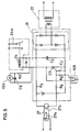
- FIG.3 is a circuit diagram of the switch with pre-alarm means in accordance with the present invention.
- FIG.4 is a circuit diagram showing details of the pre-alarm circuit 20 shown in FIG.3.
- FIG.5 is a circuit diagram showing details of a pre-alarm output circuit 21 shown in FIG.3.
- FIGs. 1, 2, 3, 4 and 5 A preferred embodiment of a switch with pre-alarm means in accordance with the present invention is described referring to FIGs. 1, 2, 3, 4 and 5.
- FIG.1 is a perspective view showing a switch with pre-alarm means in accordance with the present invention.
- the switch 101 comprises a breaker and a pre-alarm apparatus in a housing 102.
- An operation indicator 103 which is, for example, a light emitting diode (LED) is provided on the outer face of the housing 102, so that an operator can easily monitor the operation indicator 103.
- a reset switch 108 is also provided on the outer face of the housing 102.
- a lug 104 is for changing rated value of current of the switch 101, and a lug 105a is for adjusting the level of the pre-alarm of the switch.
- the lug 105a is rotatable and co-axially connected to a variable resistor such as VR1 shown in FIG.
- a level indicator 105b such as a scale for current (A) is provided around the lug 105a so that the level of the pre-alarm can be confirmed.
- numeral 106 designates an operation lever of the breaker installed in the housing 102 for making and breaking contacts thereof; and numerals 107, 107... designate terminals of the switch 101 to be connected to electric power lines and loads.
- FIG.3 is a circuit diagram of the switch with pre-alarm means in accordance with the present invention.
- current transformers CTa, CTb and CTc are disposed on three phases of A.C. power lines 5a, 5b and 5c, respectively.
- Outputs of secondary windings of the current transformers CTa, CTb and CTc are inputted to a rectifying circuit 6.
- Outputs of the rectifying circuit 6 is inputted to a peak value circuit 7 and an effective value circuit 8.
- the peak value circuit 7 selects an output from the rectifying circuit 6 corresponding to an output of the current transformers CTa, CTb and CTc including the maximum value and converts the output to a peak value.
- the effective value circuit 8 also selects an output from the rectifying circuit 6 including the maximum value and converts the output to an effective value. Output of the peak value circuit 7 is inputted to an instant time operation circuit 9 and a short time operation circuit 10. Output of the effective value circuit 8 is inputted to a long time operation circuit 11 and a pre-alarm circuit 20.
- the instant time operation circuit 9, the short time operation circuit 10 and the long time operation circuit 11 are connected to a trigger circuit 12, respectively.
- the trigger circuit 12 is connected to a tripping coil 13 and the rectifying circuit 6.
- the other terminal of the tripping coil 13 is also connected to the rectifying circuit 6.
- a light emitting diode (LED) 14 for indicating occurrence of over-current is connected to the long time operation circuit 11.
- the pre-alarm circuit 20 is connected to a pre-alarm output circuit 21 via photo-coupler 27.
- a light emitting diode (LED) 103 for pre-alarming and a relay coil 24 for pre-alarming are connected to the pre-alarm output circuit 21.
- An electric power source 23 for controlling the switch 101 is connected to the pre-alarm output circuit 21 via a voltage dropping element 22 such as a voltage transformer (VT).
- An alarm buzzer 26 is connected to the power source 23 via switch 24a.
- the switch 24a is opened and closed by operation of the relay coil 24 for pre-alarming so that the alarm buzzer 26 can be controlled.
- FIG.4 is a circuit diagram for showing details of the pre-alarm circuit 20 in FIG.3.
- terminals designated by V+,V- and SGND are respectively connected to an electric power source of an over-current tripping circuit which is not shown in the drawings.
- V ref is a reference voltage, which is kept, for example, at 4V.
- Voltage at a terminal designated by VR ref is changeable due to the rated value of the current and set at, for example, 4V when the rated value is 400A and set at 2V when the rated value is 200A.
- the Non-inverted terminal of a first comparator CM1 is connected to a variable resistor VR1 and the voltage thereof is changed by the setting of the variable resistor VR1.
- the variable resistor VR1 is used for setting the pre-alarm level of the value of the current, and is co-axially provided on the lug 105a shown in FIG.1.
- a D.C. signal which is in proportion to the effective value of the current flowing on a main circuit, for example, electric power line 5a, 5b or 5c, is applied to a terminal designated by RMST.
- the signal on the terminal designated by RMST is the output of the effective value circuit 8.
- a switch Q1 When the level of the D.C. signal on the terminal of RMST is above the reference voltage V ref of the first comparator CM1, a switch Q1 is turned off from its on state.
- the Non-inverted terminal of a second comparator CM2 is supplied with a reference voltage divided by resistors R12 and R13.
- the Inverted terminal of the second comparator CM2 is connected to a point P1 which is a connecting point of resistors R8 and R10 connected between V ref and SGND in series.
- a capacitor C4 is connected to the resistor R10 in parallel.
- FIG.5 is a circuit diagram showing details of the pre-alarm output circuit 21.
- LED 27a when LED 27a is lighted by an output signal from the pre-alarm circuit 20, photo-transistor 27b of the photo-coupler 27 turns on.
- the photo-transistor 27b turns on, current flows to gate of thyristor CR via resistor R3, transistor 27b and resistor R9.
- the thyristor CR turns on, current flows on the relay coil 24 and switch 24a is turned on by electro-magnetic force of the relay coil 24. Since the alarm buzzer 26 is connected in series to the switch 24a as shown in FIG.3, when the normal open switch 24a is turned on the alarm buzzer 26 is driven.
- a smoothing capacitor C3 of FIG.5 is for smoothing full-wave rectified current and a capacitor C5 is for preventing erroneous lighting of the operation indicator (LED) 103 due to large overcurrent of the main circuit.
- the lug 105a for adjusting the level of the pre-alarm of the switch 101 is to be turned when monitoring the operation indicator (LED) 103.
- the level of the pre-alarm is gradually reduced from the rated value of current designated by numeral 8.
- the operation indicator (LED) 103 is lighted at a position on the line 9
- the value on the line 9 shows the value of the current flowing on the load.
- the line 9 shows a ratio of 80% of the current rated value of the current shown by line 8.
- the rated value of the current is 150A
- the actual value of the current flowing on the load is 120A.
- line 10 shows the characteristics of the over-current tripping of the breaker.
Landscapes
- Emergency Protection Circuit Devices (AREA)
- Breakers (AREA)
- Measurement Of Current Or Voltage (AREA)
Claims (2)
- Schalter mit Vorwarneinrichtung (20, 21), mit:
einem Unterbrecher (11 bis 13) zum Trennen von Kontakten (4), wenn der Strom in irgendeiner aus einer Mehrzahl von elektrischen Stromleitungen (5a, 5b, 5c) einen Nennstromwert überschreitet,
einer Vorwarneinrichtung (20, 21) zur Alarmgabe, daß ein oberhalb eines vorbestimmten Pegels liegender Strom in einer aus der Mehrzahl von elektrischen Stromleitungen (5a, 5b, 5c) fließt, vor dem Auslösen des Unterbrechers,
einer Vorwarn-Anzeigeeinrichtung (103) zum Anzeigen der Betätigung der Vorwarneinrichtung (20, 21), wobei die Vorwarn-Anzeigeeinrichtung an einer äußeren Fläche eines Gehäuses (102) des Schalters vorgesehen ist,
wobei die Vorwarneinrichtung (20, 21) eine Vorwarn-Beurteilungsschaltung (20) zum Vergleichen des Werts des in einer der elektrischen Stromleitungen (5a, 5b, 5c) fließenden Stroms mit dem vorbestimmten Pegel und zum Abgeben eines Signals, wenn der Stromwert oberhalb des vorbestimmten Pegels liegt, sowie eine Vorwarn-Abgabeschaltung (21) zum Ansteuern der Vorwarn-Anzeigeeinrichtung (103) bei Empfang des Signals umfaßt,
dadurch gekennzeichnet, daß
die Vorwarn-Beurteilungsschaltung (20) den maximalen Wert der in der Mehrzahl von elektrischen Stromleitungen (5a, 5b, 5c) fließenden Ströme mit dem vorbestimmten Pegel vergleicht,
daß eine Pegeleinstelleinrichtung (VR1, 105a, 105b) zum manuellen Einstellen des vorbestimmten Pegels innerhalb eines Bereichs unterhalb des Nennstromwerts vorgesehen ist, wobei die Pegeleinstelleinrichtung einen Pegelanzeiger (105b) aufweist, der an der äußeren Fläche des Gehäuses (102) vorgesehen ist, und den vorbestimmten Pegel aus einer Spannung (VRref) gewinnt, die von dem Nennstromwert abhängt. - Schalter nach Anspruch 1, mit:
einer Stromtransformatoreinrichtung (CTa, CTb, CTc), die an den elektrischen Stromleitungen (5a, 5b, 5c) zum Abgeben elektrischer Ströme, die den Werten der in den elektrischen Stromleitungen fließenden Strömen entsprechen, vorgesehen ist,
zumindest einer Maximalwert-Erfassungseinrichtung (8) zum Erfassen des maximalen Werts der elektrischen Ströme der Stromtransformatoreinrichtung (CTa, CTb, CTc) und zum Abgeben des maximalen Werts,
wobei die Vorwarn-Beurteilungsschaltung (20) den maximalen Wert mit dem vorbestimmten Pegel vergleicht.
Applications Claiming Priority (2)
| Application Number | Priority Date | Filing Date | Title |
|---|---|---|---|
| JP63167686A JP2957583B2 (ja) | 1988-07-07 | 1988-07-07 | 事前警報装置付遮断器 |
| JP167686/88 | 1988-07-07 |
Publications (3)
| Publication Number | Publication Date |
|---|---|
| EP0349930A2 EP0349930A2 (de) | 1990-01-10 |
| EP0349930A3 EP0349930A3 (en) | 1990-08-08 |
| EP0349930B1 true EP0349930B1 (de) | 1994-11-09 |
Family
ID=15854350
Family Applications (1)
| Application Number | Title | Priority Date | Filing Date |
|---|---|---|---|
| EP89112004A Expired - Lifetime EP0349930B1 (de) | 1988-07-07 | 1989-06-30 | Schalter mit Voralarm |
Country Status (5)
| Country | Link |
|---|---|
| EP (1) | EP0349930B1 (de) |
| JP (1) | JP2957583B2 (de) |
| KR (1) | KR910008186B1 (de) |
| DE (1) | DE68919284T2 (de) |
| ZA (1) | ZA895071B (de) |
Families Citing this family (5)
| Publication number | Priority date | Publication date | Assignee | Title |
|---|---|---|---|---|
| BE1007471A5 (fr) * | 1993-09-08 | 1995-07-11 | Teco Sa | Module de controle electronique d'un disjoncteur. |
| EP0898349A1 (de) * | 1997-08-16 | 1999-02-24 | Asomatic AG | Stromüberwachungsvorrichtung und Verfahren zur Stromüberwachung |
| KR100389500B1 (ko) * | 2000-12-23 | 2003-06-25 | 김용학 | 전자개폐기 |
| SG189581A1 (en) * | 2011-10-21 | 2013-05-31 | Schneider Electric South East Asia Hq Pte Ltd | A relay with an intermediate alert mechanism |
| CN103439654A (zh) * | 2013-09-17 | 2013-12-11 | 武汉大学 | 一种高压直流开关状态检测方法 |
Citations (2)
| Publication number | Priority date | Publication date | Assignee | Title |
|---|---|---|---|---|
| FR2497013A1 (fr) * | 1980-12-19 | 1982-06-25 | Merlin Gerin | Dispositif de delestage d'une installation electrique basse tension |
| DE3501353A1 (de) * | 1985-01-17 | 1986-07-17 | Greiwe, Hermann | Geraet zur feststellung eines fehlerstroms |
Family Cites Families (8)
| Publication number | Priority date | Publication date | Assignee | Title |
|---|---|---|---|---|
| JPS5192657A (de) * | 1975-02-12 | 1976-08-13 | ||
| IT1128668B (it) * | 1980-07-29 | 1986-06-04 | Bruno Basini | Indicatore elettronico della corrente assorbita espressa in valore percentuale rispetto ad un limite prefissato superando il quale si attiva un allarme acustico |
| JPS5944133U (ja) * | 1982-09-13 | 1984-03-23 | 武井 健治 | 異常電流検出装置 |
| FR2564648B1 (fr) * | 1984-05-21 | 1989-10-13 | Merlin Gerin | Disjoncteur a declencheur electronique et a calibres multiples |
| JPS61172396U (de) * | 1985-04-11 | 1986-10-25 | ||
| FR2584877A1 (fr) * | 1985-07-29 | 1987-01-16 | Gen Electric | Circuit de reglage des fonctions de declenchement d'un disjoncteur electronique |
| JPS62180823U (de) * | 1986-05-07 | 1987-11-17 | ||
| JPS63209422A (ja) * | 1987-02-24 | 1988-08-31 | オムロン株式会社 | 電子式サ−マルリレ− |
-
1988
- 1988-07-07 JP JP63167686A patent/JP2957583B2/ja not_active Expired - Lifetime
-
1989
- 1989-01-23 KR KR1019890000686A patent/KR910008186B1/ko not_active Expired
- 1989-06-30 DE DE68919284T patent/DE68919284T2/de not_active Expired - Fee Related
- 1989-06-30 EP EP89112004A patent/EP0349930B1/de not_active Expired - Lifetime
- 1989-07-04 ZA ZA895071A patent/ZA895071B/xx unknown
Patent Citations (2)
| Publication number | Priority date | Publication date | Assignee | Title |
|---|---|---|---|---|
| FR2497013A1 (fr) * | 1980-12-19 | 1982-06-25 | Merlin Gerin | Dispositif de delestage d'une installation electrique basse tension |
| DE3501353A1 (de) * | 1985-01-17 | 1986-07-17 | Greiwe, Hermann | Geraet zur feststellung eines fehlerstroms |
Also Published As
| Publication number | Publication date |
|---|---|
| JP2957583B2 (ja) | 1999-10-04 |
| EP0349930A3 (en) | 1990-08-08 |
| JPH0223018A (ja) | 1990-01-25 |
| ZA895071B (en) | 1990-04-25 |
| DE68919284D1 (de) | 1994-12-15 |
| KR900002375A (ko) | 1990-02-28 |
| DE68919284T2 (de) | 1995-04-06 |
| KR910008186B1 (ko) | 1991-10-10 |
| EP0349930A2 (de) | 1990-01-10 |
Similar Documents
| Publication | Publication Date | Title |
|---|---|---|
| US4914541A (en) | Solid-state trip device comprising an instantaneous tripping circuit independent from the supply voltage | |
| US5559719A (en) | Digitally controlled circuit interrupter with improved automatic selection of sampling interval for 50 Hz and 60 Hz power systems | |
| US4682264A (en) | Circuit breaker with digital solid-state trip unit fitted with a calibration circuit | |
| US4694373A (en) | Circuit breaker with digital solid-state trip unit with optional functions | |
| US4689712A (en) | Circuit breaker with solid-state trip unit with a digital processing system shunted by an analog processing system | |
| CA1305245C (en) | Circuit interrupter apparatus with an integral trip curve display | |
| CA2079183C (en) | Electronic circuit breaker with protection against sputtering arc faults and ground faults | |
| CA1151279A (en) | Solid state trip unit for an electrical circuit breaker | |
| US4358810A (en) | Circuit breaker with alarm | |
| GB2073970A (en) | Circuit interrupter with energy management functions | |
| GB2073975A (en) | Circuit interrupter power supply | |
| CA1305244C (en) | Circuit interrupter apparatus with a style saving rating plug | |
| GB2074406A (en) | Circuit interrupter with remote indicator and power supply | |
| CA2012020A1 (en) | Fault-powered power supply | |
| KR100464596B1 (ko) | 과부하 검출 회로 차단기 | |
| US5283553A (en) | Switch with pre-alarm means | |
| EP0133968B1 (de) | Festkörperüberstromdetektor | |
| EP0349929B1 (de) | Schalter mit Voralarm | |
| AU604522B2 (en) | Circuit interrupter apparatus with a style saving override circuit | |
| CA2145471C (en) | Overcurrent trip unit with separately adjustable neutral protection | |
| US4429340A (en) | Bargraph displays for static trip circuit breakers | |
| EP0349930B1 (de) | Schalter mit Voralarm | |
| US4897756A (en) | Add-on ground fault module | |
| US5841618A (en) | Power-line trip circuit | |
| HK1007217B (en) | Circuit breaker including selectively operable long-time-delay tripping circuit |
Legal Events
| Date | Code | Title | Description |
|---|---|---|---|
| PUAI | Public reference made under article 153(3) epc to a published international application that has entered the european phase |
Free format text: ORIGINAL CODE: 0009012 |
|
| 17P | Request for examination filed |
Effective date: 19890630 |
|
| AK | Designated contracting states |
Kind code of ref document: A2 Designated state(s): CH DE FR GB IT LI |
|
| PUAL | Search report despatched |
Free format text: ORIGINAL CODE: 0009013 |
|
| AK | Designated contracting states |
Kind code of ref document: A3 Designated state(s): CH DE FR GB IT LI |
|
| 17Q | First examination report despatched |
Effective date: 19921014 |
|
| GRAA | (expected) grant |
Free format text: ORIGINAL CODE: 0009210 |
|
| AK | Designated contracting states |
Kind code of ref document: B1 Designated state(s): CH DE FR GB IT LI |
|
| REF | Corresponds to: |
Ref document number: 68919284 Country of ref document: DE Date of ref document: 19941215 |
|
| ITF | It: translation for a ep patent filed | ||
| ET | Fr: translation filed | ||
| PLBE | No opposition filed within time limit |
Free format text: ORIGINAL CODE: 0009261 |
|
| STAA | Information on the status of an ep patent application or granted ep patent |
Free format text: STATUS: NO OPPOSITION FILED WITHIN TIME LIMIT |
|
| 26N | No opposition filed | ||
| PGFP | Annual fee paid to national office [announced via postgrant information from national office to epo] |
Ref country code: CH Payment date: 19980708 Year of fee payment: 10 |
|
| ITPR | It: changes in ownership of a european patent |
Owner name: OFFERTA DI LICENZA AL PUBBLICO;AL PUBBLICO |
|
| REG | Reference to a national code |
Ref country code: GB Ref legal event code: 746 Effective date: 19990519 |
|
| PG25 | Lapsed in a contracting state [announced via postgrant information from national office to epo] |
Ref country code: LI Free format text: LAPSE BECAUSE OF NON-PAYMENT OF DUE FEES Effective date: 19990630 Ref country code: CH Free format text: LAPSE BECAUSE OF NON-PAYMENT OF DUE FEES Effective date: 19990630 |
|
| REG | Reference to a national code |
Ref country code: FR Ref legal event code: D6 |
|
| REG | Reference to a national code |
Ref country code: CH Ref legal event code: PL |
|
| REG | Reference to a national code |
Ref country code: GB Ref legal event code: IF02 |
|
| PGFP | Annual fee paid to national office [announced via postgrant information from national office to epo] |
Ref country code: FR Payment date: 20020610 Year of fee payment: 14 |
|
| PGFP | Annual fee paid to national office [announced via postgrant information from national office to epo] |
Ref country code: GB Payment date: 20020626 Year of fee payment: 14 |
|
| PGFP | Annual fee paid to national office [announced via postgrant information from national office to epo] |
Ref country code: DE Payment date: 20020702 Year of fee payment: 14 |
|
| PG25 | Lapsed in a contracting state [announced via postgrant information from national office to epo] |
Ref country code: GB Free format text: LAPSE BECAUSE OF NON-PAYMENT OF DUE FEES Effective date: 20030630 |
|
| PG25 | Lapsed in a contracting state [announced via postgrant information from national office to epo] |
Ref country code: DE Free format text: LAPSE BECAUSE OF NON-PAYMENT OF DUE FEES Effective date: 20040101 |
|
| GBPC | Gb: european patent ceased through non-payment of renewal fee |
Effective date: 20030630 |
|
| PG25 | Lapsed in a contracting state [announced via postgrant information from national office to epo] |
Ref country code: FR Free format text: LAPSE BECAUSE OF NON-PAYMENT OF DUE FEES Effective date: 20040227 |
|
| REG | Reference to a national code |
Ref country code: FR Ref legal event code: ST |
|
| PG25 | Lapsed in a contracting state [announced via postgrant information from national office to epo] |
Ref country code: IT Free format text: LAPSE BECAUSE OF NON-PAYMENT OF DUE FEES Effective date: 20050630 |