EP0349907A2 - Elektrooptischer Lichtablenker - Google Patents
Elektrooptischer Lichtablenker Download PDFInfo
- Publication number
- EP0349907A2 EP0349907A2 EP89111885A EP89111885A EP0349907A2 EP 0349907 A2 EP0349907 A2 EP 0349907A2 EP 89111885 A EP89111885 A EP 89111885A EP 89111885 A EP89111885 A EP 89111885A EP 0349907 A2 EP0349907 A2 EP 0349907A2
- Authority
- EP
- European Patent Office
- Prior art keywords
- refractive index
- optical beam
- parallel
- electrodes
- electrooptic
- Prior art date
- Legal status (The legal status is an assumption and is not a legal conclusion. Google has not performed a legal analysis and makes no representation as to the accuracy of the status listed.)
- Withdrawn
Links
Images
Classifications
-
- G—PHYSICS
- G02—OPTICS
- G02F—OPTICAL DEVICES OR ARRANGEMENTS FOR THE CONTROL OF LIGHT BY MODIFICATION OF THE OPTICAL PROPERTIES OF THE MEDIA OF THE ELEMENTS INVOLVED THEREIN; NON-LINEAR OPTICS; FREQUENCY-CHANGING OF LIGHT; OPTICAL LOGIC ELEMENTS; OPTICAL ANALOGUE/DIGITAL CONVERTERS
- G02F1/00—Devices or arrangements for the control of the intensity, colour, phase, polarisation or direction of light arriving from an independent light source, e.g. switching, gating or modulating; Non-linear optics
- G02F1/29—Devices or arrangements for the control of the intensity, colour, phase, polarisation or direction of light arriving from an independent light source, e.g. switching, gating or modulating; Non-linear optics for the control of the position or the direction of light beams, i.e. deflection
- G02F1/292—Devices or arrangements for the control of the intensity, colour, phase, polarisation or direction of light arriving from an independent light source, e.g. switching, gating or modulating; Non-linear optics for the control of the position or the direction of light beams, i.e. deflection by controlled diffraction or phased-array beam steering
Definitions
- the present invention concerns optical devices and more particularly an electrooptic deflector.
- the deflection of a collimated light-beam is to be controlled by an electrical signal so as to illuminate preferential regions, as in printing machines or fixed-image reading machines, to modulate or switch optical signals, such as in the equipments for optical fibre transmission systems, to process signals in scientific apparatuses, etc.
- the beam collimated at the input is to be kept, as far as possible, collimated at the output after deflection to avoid drawbacks, e.g., to avoid coupling losses with optical fibres whenever the beam is focused with an angle larger than the acceptance angle.
- a more sophisticated technique handles an optical beam with acousto-optic means, (see page 517 of the book entitled "Acoustic waves", written by Gordon S. Kino, Prentice-Hall).
- a plane acoustic wave is launched into a crystal to cause a periodic structure of material rarefaction and compression regions.
- a sequence of higher refractive-index zones alternated with lower-refractive index zones wholly equivalent to a diffraction grating, is obtained.
- the light beam is launched into the crystal at a convenient angle with respect to the grating lines and at the output a reflected beam is obtained with an angle dependant on the acoustic signal wavelength.
- deflection angles obtained are rather small: typically they are of the order of a few degrees.
- electrooptic devices comprising the one described in the U.S. Patent No. 4,415,226, still consist of a plate of electrooptic material with electrodes separately fed and connected to a control apparatus.
- a Bragg grating is implemented, wherein the deflection angle of the outgoing beam is function of the input angle and of the grating spacing, which cannot be modified once the device has been fabricated, hence only two directions of the outgoing optical beam are possible.
- the electrooptic deflector provided by the present invention, which allows a guided and collimated optical beam to be deflected by an angle of several ten degrees, by keeping it collimated, with a considerable deflection velocity and without mechanical parts in movement.
- the present invention provides an electrooptic deflector as described in claim 1.
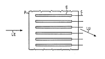
- the deflector consists of a plate made of electrooptic material, namely a material whose refractive index can be modified by applying an electric field.
- An electric field capable of giving origin to periodic variations of refractive index, is applied to said material to obtain an operation similar to that of a phase diffraction grating.
- a material of this kind may be, e.g., lithium niobate.
- Electrodes E are deposited on a plane face of plate P.
- a plane face, perpendicular to that containing the electrodes, allows the input of collimated optical beam LE into the guide and another plane face, parallel thereto, allows the output of deflected beam LU.
- the electrodes E are shaped as longitudinal stripes.
- Each conductor C is connected to a voltage source, with a value permitting the generation in the crystal of parallel regions with a different, e.g. increasing or decreasing, refractive index.
- a different, e.g. increasing or decreasing, refractive index e.g. increasing or decreasing
- Collimated optical beam LE is sent into this grating in direction parallel to the electrodes.
- the phase of the optical front of beam LU outgoing from the plurality of electrically-obtained slits results controlled and such as to generate a constructive interference in the desired direction, analogously to what happens for synthetic aperture antennas.
- the voltages applied are such as to provide equal refractive indices in all the optical paths, the outgoing beam LE will not be deflected.
- N and d denote the electrode number and the spacing between one another.
- the voltages applied to the electrodes can be controlled by a microprocessor programmed to supply the most convenient values in function of the required deflection angle, which can attain value of some ten degrees.
Landscapes
- Physics & Mathematics (AREA)
- Nonlinear Science (AREA)
- General Physics & Mathematics (AREA)
- Optics & Photonics (AREA)
- Optical Integrated Circuits (AREA)
- Optical Modulation, Optical Deflection, Nonlinear Optics, Optical Demodulation, Optical Logic Elements (AREA)
Applications Claiming Priority (2)
| Application Number | Priority Date | Filing Date | Title |
|---|---|---|---|
| IT67631/88A IT1223661B (it) | 1988-07-04 | 1988-07-04 | Deflettore elettro ottico |
| IT6763188 | 1988-07-04 |
Publications (2)
| Publication Number | Publication Date |
|---|---|
| EP0349907A2 true EP0349907A2 (de) | 1990-01-10 |
| EP0349907A3 EP0349907A3 (de) | 1991-03-20 |
Family
ID=11304062
Family Applications (1)
| Application Number | Title | Priority Date | Filing Date |
|---|---|---|---|
| EP19890111885 Withdrawn EP0349907A3 (de) | 1988-07-04 | 1989-06-30 | Elektrooptischer Lichtablenker |
Country Status (4)
| Country | Link |
|---|---|
| US (1) | US4930853A (de) |
| EP (1) | EP0349907A3 (de) |
| JP (1) | JPH0264619A (de) |
| IT (1) | IT1223661B (de) |
Cited By (1)
| Publication number | Priority date | Publication date | Assignee | Title |
|---|---|---|---|---|
| US6865310B2 (en) | 2002-08-09 | 2005-03-08 | Fujitsu Limited | Multi-layer thin film optical waveguide switch |
Families Citing this family (15)
| Publication number | Priority date | Publication date | Assignee | Title |
|---|---|---|---|---|
| US6373620B1 (en) * | 1996-02-05 | 2002-04-16 | Corning Applied Technologies Corporation | Thin film electro-optic beam steering device |
| US6317251B1 (en) | 1996-02-05 | 2001-11-13 | Corning Applied Technologies Corporation | Thin film electro-optic beam steering device |
| US6034883A (en) * | 1998-01-29 | 2000-03-07 | Tinney; Charles E. | Solid state director for beams |
| US6281862B1 (en) * | 1998-11-09 | 2001-08-28 | University Of Washington | Scanned beam display with adjustable accommodation |
| US6765644B1 (en) * | 2000-03-01 | 2004-07-20 | Raytheon Company | Broadband optical beam steering system and method |
| US6567206B1 (en) | 2001-12-20 | 2003-05-20 | St. Clair Intellectual Property Consultants, Inc. | Multi-stage optical switching device |
| US7177494B1 (en) | 2005-01-14 | 2007-02-13 | St. Clair Intellectual Property Consultants, Inc. | Optical control device and method |
| US7495815B2 (en) * | 2005-01-24 | 2009-02-24 | Nova Trans Group S.A. | Electro-optical modulator |
| US8184280B2 (en) * | 2008-04-03 | 2012-05-22 | Koninklijke Philips Electronics N.V. | Controllable light angle selector |
| US8402637B2 (en) * | 2008-11-04 | 2013-03-26 | Chief Automotive Technologies, Inc. | Vehicle fixture with alignment target |
| RU2512597C1 (ru) * | 2012-10-01 | 2014-04-10 | Федеральное государственное бюджетное образовательное учреждение высшего профессионального образования "Самарский государственный аэрокосмический университет имени академика С.П. Королева (национальный исследовательский университет)" (СГАУ) | Способ отклонения светового пучка |
| TWI575257B (zh) * | 2012-12-17 | 2017-03-21 | 鴻海精密工業股份有限公司 | 光學耦合透鏡以及光學通訊模組 |
| TW201426153A (zh) * | 2012-12-24 | 2014-07-01 | Hon Hai Prec Ind Co Ltd | 光調變器 |
| RU2571582C2 (ru) * | 2013-08-13 | 2015-12-20 | Корпорация "САМСУНГ ЭЛЕКТРОНИКС Ко., Лтд." | Отклоняющая система для управления плоской электромагнитной волной |
| US9829663B2 (en) | 2014-02-25 | 2017-11-28 | Empire Technology Development Llc | Silicon chip with refractive index gradient for optical communication |
Family Cites Families (7)
| Publication number | Priority date | Publication date | Assignee | Title |
|---|---|---|---|---|
| FR2356965A1 (fr) * | 1976-07-02 | 1978-01-27 | Thomson Csf | Deflecteur magneto-optique |
| US4386827A (en) * | 1980-10-27 | 1983-06-07 | Xerox Corporation | Electrooptical scanning device |
| US4415226A (en) * | 1980-12-31 | 1983-11-15 | Battelle Memorial Institute | Apparatus for controlling light in electrooptic waveguides with individually addressable electrodes |
| SE447935B (sv) * | 1981-04-27 | 1986-12-22 | Optisk Forskning Inst | Linslos spektrumanalysator |
| JPS59147327A (ja) * | 1983-02-10 | 1984-08-23 | Omron Tateisi Electronics Co | 光偏向器 |
| US4755036A (en) * | 1985-02-07 | 1988-07-05 | Brother Kogyo Kabushiki Kaisha | Apparatus for deflecting light beam |
| JPS6290628A (ja) * | 1985-10-17 | 1987-04-25 | Nippon Telegr & Teleph Corp <Ntt> | レ−ザ走査装置 |
-
1988
- 1988-07-04 IT IT67631/88A patent/IT1223661B/it active
-
1989
- 1989-06-30 EP EP19890111885 patent/EP0349907A3/de not_active Withdrawn
- 1989-07-03 JP JP1171761A patent/JPH0264619A/ja active Pending
- 1989-07-24 US US07/384,642 patent/US4930853A/en not_active Expired - Fee Related
Cited By (1)
| Publication number | Priority date | Publication date | Assignee | Title |
|---|---|---|---|---|
| US6865310B2 (en) | 2002-08-09 | 2005-03-08 | Fujitsu Limited | Multi-layer thin film optical waveguide switch |
Also Published As
| Publication number | Publication date |
|---|---|
| JPH0264619A (ja) | 1990-03-05 |
| IT1223661B (it) | 1990-09-29 |
| IT8867631A0 (it) | 1988-07-04 |
| EP0349907A3 (de) | 1991-03-20 |
| US4930853A (en) | 1990-06-05 |
Similar Documents
| Publication | Publication Date | Title |
|---|---|---|
| US4930853A (en) | Electrooptic deflector | |
| US3208342A (en) | Electro-optic light coupling of optical fibers | |
| US5153770A (en) | Total internal reflection electro-optic modulator | |
| US4614408A (en) | Electrooptic device for scanning and information modulating a plurality of light beams | |
| US6437762B1 (en) | Dynamic diffractive optical transform | |
| US5877876A (en) | Diffractive optical switch with polarizing beam splitters | |
| US3795433A (en) | Voltage induced optical waveguide means | |
| US5061048A (en) | Apparatus for optical beam steering using non-linear optical polymers | |
| US3838908A (en) | Guided light structures employing liquid crystal | |
| US3909108A (en) | Optical switch and modulator | |
| US4386827A (en) | Electrooptical scanning device | |
| US3736045A (en) | Fast optical guided wave modulator and digital deflector | |
| US6393177B2 (en) | True time delay generating system and method | |
| US3435228A (en) | Light beam controlling system | |
| EP0078454B1 (de) | Interferometrischer optischer Schalter und Modulator für ein Multimode-Fasersystem | |
| GB2177810A (en) | Optical switch | |
| CA2416282A1 (en) | Frequency modulated liquid crystal beamsteering device | |
| US3804489A (en) | Electro-optic thin-film diffraction loss modulator | |
| US3923374A (en) | High speed electro-optic waveguide modulator | |
| US4973121A (en) | Scanner | |
| US4995693A (en) | Multi-position opto-electronic switch | |
| US3787111A (en) | Electrooptic grating for scanning a beam of light | |
| EP0095563A2 (de) | Durch Wechselwirkung von zwei Lichtbündeln gesteuerter Lichtablenker | |
| US4027946A (en) | Acousto-optic guided-light beam device | |
| US4102560A (en) | Optical coupler |
Legal Events
| Date | Code | Title | Description |
|---|---|---|---|
| PUAI | Public reference made under article 153(3) epc to a published international application that has entered the european phase |
Free format text: ORIGINAL CODE: 0009012 |
|
| AK | Designated contracting states |
Kind code of ref document: A2 Designated state(s): DE FR GB NL SE |
|
| PUAL | Search report despatched |
Free format text: ORIGINAL CODE: 0009013 |
|
| AK | Designated contracting states |
Kind code of ref document: A3 Designated state(s): DE FR GB NL SE |
|
| STAA | Information on the status of an ep patent application or granted ep patent |
Free format text: STATUS: THE APPLICATION IS DEEMED TO BE WITHDRAWN |
|
| 18D | Application deemed to be withdrawn |
Effective date: 19910921 |