EP0349863B1 - Cassette for tapelike recording medium, particularly for a magnetic tape - Google Patents
Cassette for tapelike recording medium, particularly for a magnetic tape Download PDFInfo
- Publication number
- EP0349863B1 EP0349863B1 EP89111539A EP89111539A EP0349863B1 EP 0349863 B1 EP0349863 B1 EP 0349863B1 EP 89111539 A EP89111539 A EP 89111539A EP 89111539 A EP89111539 A EP 89111539A EP 0349863 B1 EP0349863 B1 EP 0349863B1
- Authority
- EP
- European Patent Office
- Prior art keywords
- cassette
- housing
- peg
- tape
- base
- Prior art date
- Legal status (The legal status is an assumption and is not a legal conclusion. Google has not performed a legal analysis and makes no representation as to the accuracy of the status listed.)
- Expired - Lifetime
Links
- 239000000463 material Substances 0.000 claims description 10
- 239000004033 plastic Substances 0.000 claims description 9
- 238000009825 accumulation Methods 0.000 claims description 6
- 238000004519 manufacturing process Methods 0.000 claims description 5
- 238000001746 injection moulding Methods 0.000 description 5
- 239000004793 Polystyrene Substances 0.000 description 2
- 239000011888 foil Substances 0.000 description 2
- 229920002223 polystyrene Polymers 0.000 description 2
- 239000011324 bead Substances 0.000 description 1
- 238000001816 cooling Methods 0.000 description 1
- 230000001419 dependent effect Effects 0.000 description 1
- 230000000694 effects Effects 0.000 description 1
- 229920003048 styrene butadiene rubber Polymers 0.000 description 1
- 239000013589 supplement Substances 0.000 description 1
- 230000009469 supplementation Effects 0.000 description 1
- 238000004804 winding Methods 0.000 description 1
Images

Classifications
-
- G—PHYSICS
- G11—INFORMATION STORAGE
- G11B—INFORMATION STORAGE BASED ON RELATIVE MOVEMENT BETWEEN RECORD CARRIER AND TRANSDUCER
- G11B23/00—Record carriers not specific to the method of recording or reproducing; Accessories, e.g. containers, specially adapted for co-operation with the recording or reproducing apparatus ; Intermediate mediums; Apparatus or processes specially adapted for their manufacture
- G11B23/02—Containers; Storing means both adapted to cooperate with the recording or reproducing means
- G11B23/04—Magazines; Cassettes for webs or filaments
- G11B23/08—Magazines; Cassettes for webs or filaments for housing webs or filaments having two distinct ends
- G11B23/087—Magazines; Cassettes for webs or filaments for housing webs or filaments having two distinct ends using two different reels or cores
- G11B23/08707—Details
- G11B23/08757—Guiding means
Definitions
- the invention relates to a cassette for a tape recording medium, in particular a magnetic tape, on at least one tape reel in a plastic housing and with at least one by means of a pin molded onto the inner surface of the housing, which at least also determines the running of the tape recording medium, and a tool for producing a such a cone.
- a tape guide roller which is rotatably mounted on a molded journal on the cassette housing.
- the tape guide roller arrangement which is designed as a hat roller with special axle journals, can advantageously be used to avoid running noises, but no measures are given against a lack of vertical alignment of the axle journal due to the injection molding production.
- the invention has for its object to improve the vertical alignment of the pin in plastic cassette housings, in particular the axle pin for movable tape guide elements with simple means and to provide a method for producing such pin.
- the object is achieved according to the invention with a cassette for a tape recording medium, in particular a magnetic tape, on at least one tape reel in a plastic housing and with at least one pin molded onto the inner surface of the housing, which at least also determines the running of the tape recording medium, in that around the Base of the pin is a material accumulation not centrally symmetrically arranged with respect to the center of the pin base is provided for the predetermined vertical orientation of the pin with respect to the inner surface of the housing.
- the pin can be an axle pin for a movably mounted tape guide element, in particular for a rotatably mounted tape guide roller.
- the material accumulation can be designed as a ring segment-shaped elevation or depression on the inner surface of the housing.
- the ring segment-shaped elevation / depression can be produced very easily using a special tool insert during injection molding.
- the support ribs around the base of the pin can be designed with an uneven volume, in particular with a different thickness.
- the support ribs can be designed as at least three radial ribs, of which the middle rib has the greatest thickness.
- the partial ring-shaped elevation can be arranged in the angular range of approximately 90 ° to 270 °, in particular approximately 180 °, around the base of the pin.
- the supplementation of the angular range can be formed as a depression in the inner surface of the housing.
- the elevation / depression in relation to the inner surface of the housing can have a height or depth of between approximately 0.2 and 0.6 mm.
- Tool inserts of the following design are expediently used to produce pins according to the invention.
- a tool insert for a pin of the cassette according to the invention can be designed with a longitudinal bore and with an end wall designed as an elevation or depression and rotatable about the center of the later axle pin and fixable.
- Another tool insert for a pin of a cassette according to the invention can be formed with a longitudinal bore for the axle journal, the supporting ribs having an unequal volume being able to be formed by corresponding grooves of different sizes on the inner surface of the longitudinal bore of the tool insert, and wherein the tool insert is formed around the central axis of the longitudinal bore is rotatably arranged and fixable.
- Each tool insert is also marked with a radial marking, e.g. formed an incision so that the tool insert can be used repeatedly and fixed in a predetermined angular position.
- a cassette 10 e.g. a compact cassette, with two coplanar, here equally sized tape windings 13 schematically shown.
- the cassette 10 also has a cassette housing 5 with a front side 6 and deflection rollers 7 for the magnetic tape 11.
- the deflecting rollers 7 are mounted on integrated, molded-on plastic center axis journals 12 which, in plan view (FIG. 1), have an inclination in the direction of the respective tape roll at an angle ⁇ of approximately 45 °.
- ⁇ of approximately 45 °
- the lower part 5A of the cassette housing 5 is shown without the deflection roller 7, but with the journal 12, the inclination of which relative to the inner surface of the cassette housing 5 becomes clear.
- the lateral offset a of the axle journal tip in the actual position relative to the target position (vertical) is about 40 to 50 ⁇ m, without further measures being taken.
- the plastic used is the impact-resistant polystyrene 427 D (a styrene-butadiene copolymer) from BASF Aktiengesellschaft, Ludwigshafen, Federal Republic of Germany. A maximum of 40 ⁇ m offset is just tolerable.
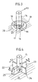
- axle journals 14 and 15 Examples of axle journals 14 and 15 according to the invention are shown in FIGS. 3 and 4.
- a narrow annular groove 17 is provided around the foot 16 of the journal 14, which is surrounded by a support or running trend 18 for the normal roller (with a continuous bearing bore).
- a somewhat lower elevation 19 is provided around this running trend 18, which may have an approximately rectangular cross-section but also other cross-sectional shapes.
- the elevation 19 has an arc length corresponding to approximately a 180 ° angle.
- the arc length can correspond to angles between approximately 90 ° and approximately 270 ° and the center of the curve elevation 19 should lie approximately in the direction of the desired vertical alignment force, here denoted by K1.
- the height of the arch elevation 19 over the inner surface 21 is the above. Material about 0.2 to 0.6 mm.
- a groove 20 can be provided on the inner surface 21 of the cassette housing 5 as a circular ring supplement.
- the groove 20 has a slightly circular cross-sectional shape, but can have any shape that is easy to produce by injection molding.
- the groove 20 can also be dispensed with entirely, but the degree of material accumulation differences is not as great as with a groove.
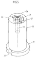
- FIG. 4 shows an axle pin 15 for a hat roller (not shown), in which radial ribs 22-24 and 25 both create a stable design and also achieve good vertical alignment according to the invention.
- the rib 25 is approximately 2 to 3 times as large in width B as the width b of the remaining narrow ribs 22-24.
- the tensile force K2 is applied, which is produced after the production of the cassette housing 5 by injection molding by cooling and shrinkage.
- the total number of ribs should be at least three, with the middle rib (s) each having the largest volume (s).
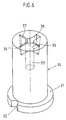
- FIG. 5 shows an example of a tool insert configuration 30 for an axle journal 14 according to FIG. 3.
- an approximately 180 ° annular recess 27 is provided around the bore 33, which corresponds to the configuration of the arch elevation 19.
- a circular groove 28 corresponds to the shape of the running end 18 and the bead elevation 29 is intended to form the approximately 180 ° ring groove 20.
- a flange 31 is formed on the tool insert 30 with an incision 32, which serves to fix the insert 30 in the tool, not shown, after rotating about the longitudinal axis L in a desired angular position (that is to say in an optimal angular position) for the axle journal 14 to be produced.
- the insert 30 is thus designed to be rotatable in its shape.
- Narrow radial slots 35-37 extend from the central bore 33, corresponding to the narrow radial ribs 22-24 of the axle journal 15, and the much wider slot 38 corresponds to the wide radial rib 25 of the journal 15 is formed.
- the outer ends of the slots 35-38 are chamfered.
- the position and volume of the respective material accumulation for the vertical alignment of the journal is also dependent on the plastic material used in each case and its shrinkage or shrinkage behavior during injection molding.
- the lateral misalignment a of the axle journals could be reduced from 40 to 50 ⁇ m to 10 to 20 ⁇ m, i.e. to at least half, which significantly increases both the reject rate in cassette manufacture and the functional reliability of the finished cassette could be.
- the description relates to axle journals for tape guide rollers or deflection rollers in audio cassettes.
- a pin is molded onto the inner surface of the housing and at least co-determines the course of the moving record carrier, it is a "guide pin".
- guide pins are either fixed pins or axle or pivot pins for movable guide elements such as guide rollers, guide levers (as used for example in the security mechanism SM® in audio cassettes from BASF Aktiengesellschaft), guide foils, pressure foils (eg in video cassettes). ® means registered trademark of BASF Aktiengesellschaft, Ludwigshafen, Germany
Landscapes
- Registering, Tensioning, Guiding Webs, And Rollers Therefor (AREA)
- Moulds For Moulding Plastics Or The Like (AREA)
- Packaging Of Annular Or Rod-Shaped Articles, Wearing Apparel, Cassettes, Or The Like (AREA)
Description
Die Erfindung betrifft eine Kassette für einen Bandaufzeichnungsträger, insbesondere ein Magnetband, auf wenigstens einem Bandwickel in einem Kunststoff-Gehäuse und mit wenigstens einer mittels eines an der Innenfläche des Gehäuses angespritzten Zapfens, der den Lauf des Bandaufzeichnungsträgers wenigstens mitbestimmt, sowie ein Werkzeug zur Herstellung eines solchen Zapfens.The invention relates to a cassette for a tape recording medium, in particular a magnetic tape, on at least one tape reel in a plastic housing and with at least one by means of a pin molded onto the inner surface of the housing, which at least also determines the running of the tape recording medium, and a tool for producing a such a cone.
Im Falle derartiger angespritzter Zapfen in Kunststoff-Gehäusen sind die Zapfen nicht ohne weiteres in einer befriedigenden Vertikallage herstellbar, da z.B. Materialschwundeinflüsse beim Abkühlen des Kunststoffs eine Neigung jedes Zapfens bewirken.In the case of such molded pins in plastic housings, the pins cannot easily be produced in a satisfactory vertical position, since e.g. Material shrinkage effects when the plastic cools cause an inclination of each pin.
Bei Achsen für bewegliche Bandführungselemente wie Führungsrollen, -hebel usw. ist die Vertikallage der Achsen jedoch zusammen mit den Toleranzen der Achsen selbst und der Bandführungselemente für die Bandführungsqualität und die Band-Kopf-Ausrichtung (wegen des Kopfspalt-Azimutwinkels) ausschlaggebend. Abweichungen von den Sollabmessungen sind auch infolge der zwangsläufigen Toleranzsummierungen Ursache für die Erhöhung des Drehmomentbedarfs (des Geräts) beim Kassetten-Betrieb sowie auch schon bei der Konfektionierung der Kassetten.In the case of axles for movable band guide elements such as guide rollers, levers etc., the vertical position of the axes together with the tolerances of the axes themselves and the band guide elements is decisive for the band guide quality and the band-head alignment (due to the head gap azimuth angle). Deviations from the nominal dimensions are also the reason for the increase in the torque requirement (of the device) during cassette operation and also during the assembly of the cassettes due to the inevitable tolerance totalization.
Aus der DE-GM 87 125 77 ist eine Bandführungsrolle bekannt, die auf einem am Kassettengehäuse angespritzten Achszapfen drehbar gelagert ist. Die als Hutrolle mit besonderen Achszapfen ausgeführte Bandführungsrollenanordnung ist zwar vorteilhaft zur Vermeidung der Laufgeräusche einsetzbar, gegen eine mangelnde Vertikal-Ausrichtung des Achszapfens aufgrund der Spritzgußherstellung sind jedoch keine Maßnahmen angegeben.From DE-GM 87 125 77 a tape guide roller is known, which is rotatably mounted on a molded journal on the cassette housing. The tape guide roller arrangement, which is designed as a hat roller with special axle journals, can advantageously be used to avoid running noises, but no measures are given against a lack of vertical alignment of the axle journal due to the injection molding production.
Die Erfindung hat sich die Aufgabe gestellt, die Vertikalausrichtung der Zapfen in Kunstoff-Kassettengehäusen, insbesondere der Achszapfen für bewegliche Bandführungselemente mit einfachen Mitteln zu verbessern und ein Verfahren zur Herstellung solcher Zapfen bereitzustellen.The invention has for its object to improve the vertical alignment of the pin in plastic cassette housings, in particular the axle pin for movable tape guide elements with simple means and to provide a method for producing such pin.
Die Aufgabe wird erfindungsgemäß mit einer Kassette für einen Bandaufzeichnungsträger, insbesondere ein Magnetband, auf wenigstens einem Bandwickel in einem Kunststoff-Gehäuse und mit wenigstens einem an der Innenfläche des Gehäuses angespritzten Zapfen, der den Lauf des Bandaufzeichnungsträgers wenigstens mitbestimmt, dadurch gelöst, daß um den Fuß des Zapfens eine in bezug auf den Mittelpunkt des Zapfenfußes nicht zentral-symmetrisch angeordnete Materialanhäufung vorgesehen ist, zur vorherbestimmbaren Vertikalausrichtung des Zapfens in bezug auf die Innenfläche des Gehäuses.The object is achieved according to the invention with a cassette for a tape recording medium, in particular a magnetic tape, on at least one tape reel in a plastic housing and with at least one pin molded onto the inner surface of the housing, which at least also determines the running of the tape recording medium, in that around the Base of the pin is a material accumulation not centrally symmetrically arranged with respect to the center of the pin base is provided for the predetermined vertical orientation of the pin with respect to the inner surface of the housing.
Damit wird erreicht, daß der Zapfen durch stärkeren Materialschwund in einer Zone um seinen Fuß in eine vorbestimmte Richtung "gezogen" wird und so eine gewünschte Zapfen-Vertikalausrichtung voreinstellbar ist.It is thereby achieved that the pin is "pulled" in a zone around its foot in a predetermined direction due to stronger material shrinkage and a desired pin vertical alignment can thus be preset.
In zweckmäßiger Ausbildung kann der Zapfen ein Achszapfen für ein beweglich gelagertes Bandführungselement, insbesondere für eine drehbar gelagerte Bandführungsrolle sein.In an expedient embodiment, the pin can be an axle pin for a movably mounted tape guide element, in particular for a rotatably mounted tape guide roller.
In weiterer Ausgestaltung der Erfindung kann die Materialanhäufung als ringsegmentförmige Erhöhung oder Vertiefung an der Gehäuseinnenfläche ausgebildet sein. Dabei läßt sich die ringsegmentförmige Erhöhung/Vertiefung sehr einfach durch einen speziellen Werkzeugeinsatz beim Spritzgießen herstellen.In a further embodiment of the invention, the material accumulation can be designed as a ring segment-shaped elevation or depression on the inner surface of the housing. The ring segment-shaped elevation / depression can be produced very easily using a special tool insert during injection molding.
In weiterer Ausgestaltung der Erfindung, wenn der Zapfen mit Stützrippen versehen ist, können die Stützrippen um den Fuß des Zapfens mit ungleichem Volumen, insbesondere mit unterschiedlicher Dicke, ausgebildet sein.In a further embodiment of the invention, if the pin is provided with support ribs, the support ribs around the base of the pin can be designed with an uneven volume, in particular with a different thickness.
Dadurch ist es auch möglich, beispielsweise Achszapfen für Hutrollen vertikalausgerichtet auszubilden.This also makes it possible, for example, to design axles for hat rollers in a vertically aligned manner.
Praktisch können die Stützrippen als mindestens drei Radialrippen ausgebildet sein, wovon die mittlere Rippe die größte Dicke aufweist.In practice, the support ribs can be designed as at least three radial ribs, of which the middle rib has the greatest thickness.
Praktisch ausgebildet kann die teilringförmige Erhöhung im Winkelbereich von etwa 90° bis 270°, insbesondere von etwa 180°, um den Fuß des Zapfens angeordnet sein.In practice, the partial ring-shaped elevation can be arranged in the angular range of approximately 90 ° to 270 °, in particular approximately 180 °, around the base of the pin.
In zweckmäßiger Ausgestaltung kann die Ergänzung des Winkelbereichs als Vertiefung in der Gehäuse-Innenfläche ausgeformt sein.In an expedient embodiment, the supplementation of the angular range can be formed as a depression in the inner surface of the housing.
Praktisch kann die Erhöhung/Vertiefung in bezug zur Innenfläche des Gehäuses eine Höhe bzw. Tiefe zwischen etwa 0,2 und 0,6 mm aufweisen.In practice, the elevation / depression in relation to the inner surface of the housing can have a height or depth of between approximately 0.2 and 0.6 mm.
Zur Herstellung erfindungsgemäßer Zapfen kommen zweckmäßig Werkzeug-Einsätze folgender Ausbildung zur Verwendung.Tool inserts of the following design are expediently used to produce pins according to the invention.
Ein Werkzeug-Einsatz für einen Zapfen der erfindungsgemäßen Kassette kann mit einer Längsbohrung und mit einer als Erhöhung bzw. Vertiefung ausgebildeten Stirnwand und drehbar um den Mittelpunkt des späteren Achszapfens und fixierbar ausgeführt sein.A tool insert for a pin of the cassette according to the invention can be designed with a longitudinal bore and with an end wall designed as an elevation or depression and rotatable about the center of the later axle pin and fixable.
Ein weiterer Werkzeug-Einsatz für einen Zapfen einer erfindungsgemäßen Kassette kann mit einer Längsbohrung für den Achszapfen ausgebildet sein, wobei die Stützrippen mit ungleichem Volumen durch entsprechende Nuten unterschiedlicher Größe an der Innenfläche der Längsbohrung des Werkzeug-Einsatzes ausbildbar sind und wobei der Werkzeug-Einsatz um die Mittelachse der Längsbohrung drehbar angeordnet und fixierbar ist.Another tool insert for a pin of a cassette according to the invention can be formed with a longitudinal bore for the axle journal, the supporting ribs having an unequal volume being able to be formed by corresponding grooves of different sizes on the inner surface of the longitudinal bore of the tool insert, and wherein the tool insert is formed around the central axis of the longitudinal bore is rotatably arranged and fixable.
Jeder Werkzeug-Einsatz ist außerdem mit einer radialen Kennzeichnung, z.B. einem Einschnitt ausgebildet, so daß der Werkzeug-Einsatz in vorherbestimmter Winkellage wiederholbar einzusetzen und fixierbar ist.Each tool insert is also marked with a radial marking, e.g. formed an incision so that the tool insert can be used repeatedly and fixed in a predetermined angular position.
Mit einem erfindungsgemäßen Werkzeug-Einsatz ist es möglich, eine bewußte oder notwendige Achsschrägstellung zu realisieren.With a tool insert according to the invention, it is possible to realize a conscious or necessary axial inclination.
Ausführungsbeispiele er Erfindung sind in der Zeichnung dargestellt und nachfolgend beschrieben.Embodiments of the invention are shown in the drawing and described below.
Es zeigen
- Figur 1 eine Draufsicht einer Kompakt-Kassette mit Umlenkrollen auf Achszapfen
- Figur 2 die Kassette mit den Achszapfen in Seitenansicht in Richtung A der Figur 1
- Figur 3 einen ersten erfindungsgemäße Zapfen in Perspektive
- Figur 4 einen zweiten erfindungsgemäßen Zapfen in Perspektive
- Figur 5 einen Werkzeug-Einsatz für den erfindungsgemäßen Zapfen in Figur 4
Figur 6 einen weiteren Werkzeug-Einsatz für den erfindungsgemäßen Zapfen in Figur 5
- Figure 1 is a plan view of a compact cassette with pulleys on journal
- Figure 2 shows the cassette with the journal in side view in direction A of Figure 1
- Figure 3 shows a first pin according to the invention in perspective
- Figure 4 shows a second pin according to the invention in perspective
- 5 shows a tool insert for the pin according to the invention in FIG. 4
- 6 shows a further tool insert for the pin according to the invention in FIG. 5
In Figur 1 ist eine Kassette 10, z.B. eine Kompakt-Kassette, mit zwei koplanaren, hier gleichgroßen Bandwickeln 13 Schematisch dargestellt. Außerdem weist die Kassette 10 noch ein Kassettengehäuse 5 mit einer Frontseite 6 sowie Umlenkrollen 7 für das Magnetband 11 auf. Die Umlenkrollen 7 sind auf integrierten, hier angespritzten Kunststoff-Mittelachszapfen 12 gelagert, die in Draufsicht (Figur 1) eine Neigung in die Richtung des jeweiligen Bandwickels im Winkel α von etwa 45° haben. Bei anderer Formgestaltung für die Kassettenteile sind andere Neigungswinkel zu erwarten.In Figure 1 a
In Figur 2 ist das Unterteil 5A des Kassettengehäuses 5 ohne die Umlenkrolle 7, jedoch mit Achszapfen 12, dessen Neigung gegenüber der Innenfläche des Kassettengehäuses 5 deutlich wird, gezeigt. Der seitliche Versatz a der Achszapfenspitze in Istlage gegenüber der Sollage (Vertikalen) beträgt gemäß dem Stand der Technik, ohne daß weitere Maßnahmen getroffen sind, etwa 40 bis 50 µm. Der verwendete Kunststoff ist das schlagfeste Polystyrol 427 D (ein Styrolbutadien-Copolymer) der BASF Aktiengesellschaft, Ludwigshafen, Bundesrepublik Deutschland. Dabei ist maximal 40 µm Versatz noch gerade tolerierbar.In FIG. 2, the
Erfindungsgemäße Beispiele von Achszapfen 14 und 15 sind in Figuren 3 und 4 dargestellt.Examples of
In Figur 3 ist um den Fuß 16 des Achszapfens 14 eine schmale Ringnut 17 vorgesehen, die von einem Auflage- oder Laufrend 18 für die Normalrolle (mit durchgehender Lagerbohrung) umgeben ist. Um diesen Laufrend 18 ist eine etwas niedrigere Erhöhung 19 vorgesehen, die etwa rechteckförmigen Querschnitt aber auch andere Querschnittsformen besitzen kann. Die Erhöhung 19 hat eine Bogenlänge entsprechend etwa einem 180°-Winkel. Die Bogenlänge kann Winkeln zwischen etwa 90° und etwa 270° entsprechen und die Mitte der Bogenerhöhung 19 sollte etwa in der Richtung der gewünschten Vertikalausrichtkraft, hier mit K1 bezeichnet, liegen. Die Höhe der Bogenerhöhung 19 über der Innenfläche 21 beträgt beim o.g. Werkstoff etwa 0,2 bis 0,6 mm. Als Kreisringergänzung kann eine Nut 20 an der Innenfläche 21 des Kassettengehäuses 5 vorgesehen sein. Die Nut 20 hat andeutungsweise eine leicht kreisabschnittsförmige Querschnittsform, kann jedoch jede spritztechnisch leicht herstellbare Form aufweisen.In Figure 3, a narrow
Wie in Figur 3 angedeutet, kann auf die Nut 20 auch ganz verzichtet werden, wodurch der Grad der Materialanhäufungsunterschiede jedoch nicht so groß ist wie mit einer Nut.As indicated in FIG. 3, the
In Figur 4 ist ein Achszapfen 15 für eine Hutrolle (nicht dargestellt) gezeigt, bei dem durch Radialrippen 22-24 und 25 sowohl eine stabile Ausführung geschaffen wird, als auch eine gute Vertikal-Ausrichtung gemäß der Erfindung erreichbar ist. Die Rippe 25 ist in der Breite B etwa 2 bis 3 mal so groß ausgebildet wie die Breite b der übrigen schmalen Rippen 22-24. Dadurch wird die Zugkraft K2 aufgebracht, die nach der Herstellung der Kassettengehäuse 5 im Spritzguß durch Abkühlung und Schwund erzeugt wird. Die Gesamtzahl der Rippen sollte wenigstens drei betragen, wobei jeweils die mittlere(n) Rippe(n) das größte Volumen besitzen sollte(n).FIG. 4 shows an
Figur 5 zeigt ein Beispiel für eine Werkzeug-Einsatz-Ausbildung 30 für einen Achszapfen 14 gemäß Figur 3. In der Stirnwand 26 ist hier um die Bohrung 33 eine etwa 180° Ringvertiefung 27 vorgesehen, die der Ausbildung der Bogenerhöhung 19 entspricht. Eine Kreisnut 28 entspricht der Form des Laufrendes 18 und die Wulst-Erhöhung 29 soll der Ausbildung der etwa 180°-Ringnut 20 dienen. Ein Flansch 31 ist am Werkzeug-Einsatz 30 mit einem Einschnitt 32 ausgebildet, der zum Festlegen des Einsatzes 30 im nicht dargestellten Werkzeug nach Drehen um die Längsachse L in einer gewünschten Winkellage (also in optimaler Winkellage) zum herzustellenden Achszapfen 14 dient. Der Einsatz 30 ist somit schon von der Form her drehbar auszubilden.FIG. 5 shows an example of a
Besagtes gilt auch für den nun noch zu beschreibenden zweiten Achszapfen-Werkzeug-Einsatz 34. Von der Mittelbohrung 33 erstrecken sich schmale Radialschlitze 35-37 entsprechend den schmalen Radialrippen 22-24 des Achszapfens 15 und der wesentlich breitere Schlitz 38 ist ensprechend der breiten Radialrippe 25 des Achszapfens 15 ausgebildet. Zur besseren Entformung sind die Außenenden der Schlitze 35-38 abgeschrägt ausgeführt. Die Lage und das Volumen der jeweiligen Materialanhäufung zur Achszapfen-Vertikalausrichtung ist auch abhängig vom jeweils verwendeten Kunststoffmaterial und seinem Schwind- oder Schrumpfverhalten beim Spritzgießen.The same also applies to the second axle
Mit dem oben angegebenen schlagfesten Polystyrol-Kunstoff konnte der seitliche Versatz a der Achszapfen von 40 bis 50 µm auf 10 bis 20 µm reduziert werden, also auf wenigstens die Hälfte, wodurch sowohl die Ausschußrate bei der Kassettenherstellung als auch die Funktionssicherheit der fertigen Kassette wesentlich erhöht werden konnte.With the impact-resistant polystyrene plastic specified above, the lateral misalignment a of the axle journals could be reduced from 40 to 50 µm to 10 to 20 µm, i.e. to at least half, which significantly increases both the reject rate in cassette manufacture and the functional reliability of the finished cassette could be.
Die Beschreibung betrifft Achszapfen für Bandführungsrollen oder Umlenkrollen in Audio-Kassetten.The description relates to axle journals for tape guide rollers or deflection rollers in audio cassettes.
Es ist jedoch für jeden Fachmann zweifelsfrei, daß alle Maßnahmen für jede Art von "Führungszapfen" im weitesten Sinne in jeder Art von Kassetten einsetzbar ist, wobei es um eine möglichst gute Vertikal-Ausrichtung der Zapfen geht.However, it is beyond doubt for any person skilled in the art that all measures for every type of “guide pin” can be used in the broadest sense in every type of cassette, with the aim being the best possible vertical alignment of the pins.
Immer wenn ein Zapfen an der Innenfläche des Gehäuses angespritzt ist und derselbe wenigstens den Lauf des bewegten Aufzeichnungsträgers mitbestimmt, ist derselbe ein "Führungszapfen".Whenever a pin is molded onto the inner surface of the housing and at least co-determines the course of the moving record carrier, it is a "guide pin".
Solche "Führungszapfen" sind entweder feste Zapfen oder Achs- oder Schwenkzapfen für bewegliche führungselemente wie Führungsrollen, Führungshebel (wie z.B. in der Sicherheitsmechanik SM® in Audio-Cassetten der BASF Aktiengesellschaft benutzt), Führungsfolien, Andruckfolien (z.B. in Videokassetten).
® bedeutet eingetragenes Warenzeichen der BASF Aktiengesellschaft, Ludwigshafen, DeutschlandSuch "guide pins" are either fixed pins or axle or pivot pins for movable guide elements such as guide rollers, guide levers (as used for example in the security mechanism SM® in audio cassettes from BASF Aktiengesellschaft), guide foils, pressure foils (eg in video cassettes).
® means registered trademark of BASF Aktiengesellschaft, Ludwigshafen, Germany
Claims (10)
Applications Claiming Priority (2)
| Application Number | Priority Date | Filing Date | Title |
|---|---|---|---|
| DE8808630U | 1988-07-06 | ||
| DE8808630U DE8808630U1 (en) | 1988-07-06 | 1988-07-06 | Cassette for a tape recording medium, in particular a magnetic tape |
Publications (2)
| Publication Number | Publication Date |
|---|---|
| EP0349863A1 EP0349863A1 (en) | 1990-01-10 |
| EP0349863B1 true EP0349863B1 (en) | 1992-06-10 |
Family
ID=6825676
Family Applications (1)
| Application Number | Title | Priority Date | Filing Date |
|---|---|---|---|
| EP89111539A Expired - Lifetime EP0349863B1 (en) | 1988-07-06 | 1989-06-24 | Cassette for tapelike recording medium, particularly for a magnetic tape |
Country Status (4)
| Country | Link |
|---|---|
| US (1) | US5234178A (en) |
| EP (1) | EP0349863B1 (en) |
| JP (1) | JPH02110885A (en) |
| DE (2) | DE8808630U1 (en) |
Families Citing this family (4)
| Publication number | Priority date | Publication date | Assignee | Title |
|---|---|---|---|---|
| US5104058A (en) * | 1990-08-27 | 1992-04-14 | Gigatek Memory Systems, Inc. | Tape guidance system for belt-driven cartridge |
| US6014293A (en) * | 1994-04-22 | 2000-01-11 | Imation Corp. | Single reel cartridge erasure preventing device housing with post |
| JP3479448B2 (en) * | 1998-01-23 | 2003-12-15 | Tdk株式会社 | Tape cassette |
| NL1014096C2 (en) * | 2000-01-17 | 2001-07-18 | Onstream B V | Bobbin holder. |
Family Cites Families (8)
| Publication number | Priority date | Publication date | Assignee | Title |
|---|---|---|---|---|
| JPS5418139B1 (en) * | 1970-07-15 | 1979-07-05 | ||
| US3884430A (en) * | 1972-12-20 | 1975-05-20 | Little Inc A | Tape cassette |
| IT1192664B (en) * | 1979-01-23 | 1988-05-04 | Werbetronic Ag | IMPROVEMENT IN BELT DRAGGING VEHICLES IN BELT RECORDERS |
| JPS593423Y2 (en) * | 1980-01-14 | 1984-01-30 | ティーディーケイ株式会社 | magnetic tape cassette |
| JPH0658758B2 (en) * | 1984-12-24 | 1994-08-03 | バスフ アクチェン ゲゼルシャフト | Tape guiding device for tape feeders, in particular for magnetic tape devices and for tape cassettes |
| JPH0325354Y2 (en) * | 1985-03-27 | 1991-05-31 | ||
| DE8712577U1 (en) * | 1987-09-17 | 1987-11-12 | Basf Ag, 6700 Ludwigshafen | Cassette for a tape-shaped recording medium with at least one tape reel |
| JPH0171383U (en) * | 1987-10-29 | 1989-05-12 |
-
1988
- 1988-07-06 DE DE8808630U patent/DE8808630U1/en not_active Expired
-
1989
- 1989-06-24 DE DE8989111539T patent/DE58901622D1/en not_active Expired - Lifetime
- 1989-06-24 EP EP89111539A patent/EP0349863B1/en not_active Expired - Lifetime
- 1989-07-03 JP JP1171766A patent/JPH02110885A/en active Pending
- 1989-07-05 US US07/375,471 patent/US5234178A/en not_active Expired - Fee Related
Also Published As
| Publication number | Publication date |
|---|---|
| EP0349863A1 (en) | 1990-01-10 |
| DE58901622D1 (en) | 1992-07-16 |
| DE8808630U1 (en) | 1988-09-15 |
| JPH02110885A (en) | 1990-04-24 |
| US5234178A (en) | 1993-08-10 |
Similar Documents
| Publication | Publication Date | Title |
|---|---|---|
| DE2348994C2 (en) | Magnetic tape cassette | |
| DE3686288T2 (en) | LOCK FOR PLATE CASSETTE. | |
| DE3889378T2 (en) | Cassette type shape. | |
| EP0152572A1 (en) | Positioning device for a magnetic disc memory | |
| DE2251746C3 (en) | Magnetic tape cassette, in particular compact cassette | |
| DE2636169A1 (en) | MAGNETIC TAPE CASSETTE | |
| DE2732083C2 (en) | Magnetic tape cassette | |
| EP0349863B1 (en) | Cassette for tapelike recording medium, particularly for a magnetic tape | |
| DE3003952A1 (en) | DEVICE FOR RECORDING AND / OR PLAYING BACK SIGNALS ON A MAGNETIC TAPE | |
| DE3780150T2 (en) | SLIDING BLADE FOR MAGNETIC TAPE CASSETTES. | |
| DE2721460A1 (en) | MAGNETIC TAPE CASSETTE | |
| DE3927956A1 (en) | LEAF SPRING FOR STORING THE REELS OF A VIDEO TAPE CASSETTE | |
| DE2844168C3 (en) | Magnetic tape cassette | |
| DE1177894B (en) | Winding core with a cylindrical surface and device for producing the same | |
| DE8907834U1 (en) | Cassette for a tape recording medium, in particular a magnetic tape | |
| WO1996001472A1 (en) | Winding hub for tape-like information carriers | |
| DE69420643T2 (en) | Tape cassette | |
| DE3501912C2 (en) | Electromagnetic display device | |
| DE602004006046T2 (en) | Resin casting process for protecting the winding of a rotary encoder | |
| DE8909706U1 (en) | Tape cassette, especially magnetic tape cassette | |
| DE3327487C2 (en) | Pressure pad device for a magnetic tape cassette | |
| DE3103823A1 (en) | RING WITH RIB FOR REWINDING MAGNETIC TAPE | |
| DE4031410C2 (en) | Magnetic tape cassette housing | |
| DE2623150A1 (en) | REEL FOR A MAGNETIC TAPE CASSETTE | |
| DE2121375A1 (en) | Sliding film for magnetic tape cassettes |
Legal Events
| Date | Code | Title | Description |
|---|---|---|---|
| PUAI | Public reference made under article 153(3) epc to a published international application that has entered the european phase |
Free format text: ORIGINAL CODE: 0009012 |
|
| 17P | Request for examination filed |
Effective date: 19891017 |
|
| AK | Designated contracting states |
Kind code of ref document: A1 Designated state(s): BE CH DE FR GB IT LI NL |
|
| 17Q | First examination report despatched |
Effective date: 19911107 |
|
| GRAA | (expected) grant |
Free format text: ORIGINAL CODE: 0009210 |
|
| AK | Designated contracting states |
Kind code of ref document: B1 Designated state(s): BE CH DE FR GB IT LI NL |
|
| ITF | It: translation for a ep patent filed | ||
| GBT | Gb: translation of ep patent filed (gb section 77(6)(a)/1977) | ||
| REF | Corresponds to: |
Ref document number: 58901622 Country of ref document: DE Date of ref document: 19920716 |
|
| ET | Fr: translation filed | ||
| PLBE | No opposition filed within time limit |
Free format text: ORIGINAL CODE: 0009261 |
|
| STAA | Information on the status of an ep patent application or granted ep patent |
Free format text: STATUS: NO OPPOSITION FILED WITHIN TIME LIMIT |
|
| 26N | No opposition filed | ||
| PGFP | Annual fee paid to national office [announced via postgrant information from national office to epo] |
Ref country code: CH Payment date: 19940524 Year of fee payment: 6 |
|
| PGFP | Annual fee paid to national office [announced via postgrant information from national office to epo] |
Ref country code: FR Payment date: 19940525 Year of fee payment: 6 |
|
| PGFP | Annual fee paid to national office [announced via postgrant information from national office to epo] |
Ref country code: BE Payment date: 19940610 Year of fee payment: 6 |
|
| PGFP | Annual fee paid to national office [announced via postgrant information from national office to epo] |
Ref country code: GB Payment date: 19940616 Year of fee payment: 6 |
|
| PGFP | Annual fee paid to national office [announced via postgrant information from national office to epo] |
Ref country code: NL Payment date: 19940630 Year of fee payment: 6 |
|
| PG25 | Lapsed in a contracting state [announced via postgrant information from national office to epo] |
Ref country code: GB Effective date: 19950624 |
|
| PG25 | Lapsed in a contracting state [announced via postgrant information from national office to epo] |
Ref country code: LI Effective date: 19950630 Ref country code: CH Effective date: 19950630 Ref country code: BE Effective date: 19950630 |
|
| BERE | Be: lapsed |
Owner name: BASF A.G. Effective date: 19950630 |
|
| PG25 | Lapsed in a contracting state [announced via postgrant information from national office to epo] |
Ref country code: NL Effective date: 19960101 |
|
| GBPC | Gb: european patent ceased through non-payment of renewal fee |
Effective date: 19950624 |
|
| PG25 | Lapsed in a contracting state [announced via postgrant information from national office to epo] |
Ref country code: FR Effective date: 19960229 |
|
| REG | Reference to a national code |
Ref country code: CH Ref legal event code: PL |
|
| NLV4 | Nl: lapsed or anulled due to non-payment of the annual fee |
Effective date: 19960101 |
|
| REG | Reference to a national code |
Ref country code: FR Ref legal event code: ST |
|
| PGFP | Annual fee paid to national office [announced via postgrant information from national office to epo] |
Ref country code: DE Payment date: 20020603 Year of fee payment: 14 |
|
| PG25 | Lapsed in a contracting state [announced via postgrant information from national office to epo] |
Ref country code: DE Free format text: LAPSE BECAUSE OF NON-PAYMENT OF DUE FEES Effective date: 20040101 |
|
| PG25 | Lapsed in a contracting state [announced via postgrant information from national office to epo] |
Ref country code: IT Free format text: LAPSE BECAUSE OF NON-PAYMENT OF DUE FEES;WARNING: LAPSES OF ITALIAN PATENTS WITH EFFECTIVE DATE BEFORE 2007 MAY HAVE OCCURRED AT ANY TIME BEFORE 2007. THE CORRECT EFFECTIVE DATE MAY BE DIFFERENT FROM THE ONE RECORDED. Effective date: 20050624 |