EP0349840A2 - Rolling mill for the production of a rolling stock - Google Patents
Rolling mill for the production of a rolling stock Download PDFInfo
- Publication number
- EP0349840A2 EP0349840A2 EP89111347A EP89111347A EP0349840A2 EP 0349840 A2 EP0349840 A2 EP 0349840A2 EP 89111347 A EP89111347 A EP 89111347A EP 89111347 A EP89111347 A EP 89111347A EP 0349840 A2 EP0349840 A2 EP 0349840A2
- Authority
- EP
- European Patent Office
- Prior art keywords
- strip
- roll
- rolling mill
- deflectors
- work
- Prior art date
- Legal status (The legal status is an assumption and is not a legal conclusion. Google has not performed a legal analysis and makes no representation as to the accuracy of the status listed.)
- Withdrawn
Links
Images


Classifications
-
- B—PERFORMING OPERATIONS; TRANSPORTING
- B21—MECHANICAL METAL-WORKING WITHOUT ESSENTIALLY REMOVING MATERIAL; PUNCHING METAL
- B21B—ROLLING OF METAL
- B21B39/00—Arrangements for moving, supporting, or positioning work, or controlling its movement, combined with or arranged in, or specially adapted for use in connection with, metal-rolling mills
- B21B39/14—Guiding, positioning or aligning work
- B21B39/16—Guiding, positioning or aligning work immediately before entering or after leaving the pass
-
- B—PERFORMING OPERATIONS; TRANSPORTING
- B21—MECHANICAL METAL-WORKING WITHOUT ESSENTIALLY REMOVING MATERIAL; PUNCHING METAL
- B21B—ROLLING OF METAL
- B21B27/00—Rolls, roll alloys or roll fabrication; Lubricating, cooling or heating rolls while in use
- B21B27/06—Lubricating, cooling or heating rolls
- B21B27/10—Lubricating, cooling or heating rolls externally
-
- B—PERFORMING OPERATIONS; TRANSPORTING
- B21—MECHANICAL METAL-WORKING WITHOUT ESSENTIALLY REMOVING MATERIAL; PUNCHING METAL
- B21B—ROLLING OF METAL
- B21B13/00—Metal-rolling stands, i.e. an assembly composed of a stand frame, rolls, and accessories
- B21B13/02—Metal-rolling stands, i.e. an assembly composed of a stand frame, rolls, and accessories with axes of rolls arranged horizontally
- B21B2013/028—Sixto, six-high stands
-
- B—PERFORMING OPERATIONS; TRANSPORTING
- B21—MECHANICAL METAL-WORKING WITHOUT ESSENTIALLY REMOVING MATERIAL; PUNCHING METAL
- B21B—ROLLING OF METAL
- B21B31/00—Rolling stand structures; Mounting, adjusting, or interchanging rolls, roll mountings, or stand frames
- B21B31/16—Adjusting or positioning rolls
- B21B31/20—Adjusting or positioning rolls by moving rolls perpendicularly to roll axis
- B21B2031/206—Horizontal offset of work rolls
Definitions
- the invention relates to a rolling mill for producing a rolling stock, in particular a rolled strip, consisting of work rolls preferably arranged one above the other in a roll stand, which are optionally supported on support rolls or on support rolls and intermediate rolls, with strip deflectors, spraying devices arranged on the rolling mill on the inlet and outlet sides.
- the object of the invention is to significantly improve the construction of a rolling mill equipped with belt deflectors, spraying devices, roller belt lifting devices, extension rails and roller belt guide tables, particularly with regard to the space requirement of these additional units.
- the rolled strip lifting devices with strip deflectors, spraying devices, extension rails and rolled strip feed tables are combined to form a single unit and are arranged within the roll stand in the immediate vicinity of the roll gap of the work rolls.
- the rolled strip lifting devices with strip deflectors and the spraying devices in Integrated work roll bending block which is provided with a recess into which the roll extension rails of the chocks arranged on the work rolls engage.
- the assembly consisting of belt lifting devices with belt deflectors and spraying devices is connected to the work roll bending block so that it can move horizontally and vertically via grooves and feather keys.
- the units can be very advantageously and optimally adapted at any time to the desired changes or to the changes that occur during operation of the rolling mill, in particular with regard to the roll gap width and the axial displacement of one work roll relative to the other.
- a roll bending block designed as a work roll bending block, consisting of two parts and provided with a hydraulic adjusting device can also be used advantageously, as described and illustrated, for example, in European Patent Specification 0 059 417.
- the grooves and feather keys connecting the structural unit to the work roll bending block are inclined with respect to the vertical arranged.
- the length of the roller strip guide tables running in the plane of the rolled strip is designed to be changeable by means of mountable angle pieces.
- the structural unit consisting of strip lifting devices with strip deflectors and spraying devices is formed in two parts. This very advantageously enables the use of this unit in rolling mills with work roll diameters of any size.
- the rolling mill consists of two work rolls (2, 3), intermediate rolls (4, 5) and backup rolls (6, 7) arranged one above the other in a roll stand (1).
- the rolled strip lifting devices (8) with strip deflectors (10), spraying devices (11), extension rails (12) and rolled strip guide tables (13) are combined according to the invention into a very compact, easily accessible structural unit and arranged within the rolling stand (1).
- the rolled strip lifting devices (8) with strip deflectors (10) and spraying devices (11) are integrated in the roll bending block (15), which is very advantageously provided with recesses (16) into which the roll extension rails (12) on the work rolls (2, 3) engage chocks (17) on both sides.
- the belt lifting devices (8) with belt deflectors (10) and spraying devices (11) form a rigid unit which can be moved horizontally and vertically by means of inclined grooves (18) and feather keys (19) in the area of the work rolls (2, 3) is held in the required position by the roller bending blocks (15) in cassette design.
- the position of the multi-function block forming a rigid unit is a function of the position of the upper one and lower roll bending block (15).
- the position of the roller bending blocks (15) - due to the type of cassette - in turn depends on the chocks (17) of the horizontal and vertical position of the work rolls (2, 3) in the roll stand (1).
- this multi-function block shown in FIG. 1 and designed in accordance with the invention requires the use of work rolls which have only relatively small diameter differences (140-160 mm). However, if work rolls with larger roll diameter differences are to be used in a rolling mill, this can be easily accomplished by replacing the horizontal wear strips of the chocks (17) engaging the work rolls (2, 3).
- the length of the strip conveyor tables (13) running in the plane of the strip can also be changed in length by mountable angle pieces (20).
- the inventive design of the rolling mill also very advantageously allows the arrangement of rollers (21) for guiding and calming the rolling strip (22) and hydraulic adjustment devices (23) for the rollers (21), roller guide tables (13) etc. within the roll stand also in the vicinity of the roll gap (9).
- the desired distance between the belt deflectors (10) and the bales or the surface of the work rolls (2, 3) is determined with the maximum roll diameter and closed roll gap (9) without rolling stock.
- the distance between the roll bending block (15) arranged on the upper work roll (2) and the lower roll bending block (15) of the work roll (3) will also become correspondingly smaller in the rolling operation. Due to the inclination of the grooves (18) and feather keys (19), the multi-function block and thus the strip deflectors (10) are moved in the direction of the roll gap (9).
- the groove (28) / feather key (29) remains at a certain inclination.
- -Arrangements of the distance (30) between the surfaces of the work rolls (24, 25) and the belt deflectors (31) almost constant, ie the roll grinding is completely and automatically compensated.
- the rolled strip (32) touches the lower work roll (25) and is guided optimally.
- the distance (30) between the surfaces of the work rolls (24, 25) and the strip deflectors (31) is also influenced by the rolling stock located between the work rolls during operation of the rolling mill; however, this is of no importance, since the distance difference is negligible for thin strips of, for example, 0.2 mm, and for thick strips of, for example, 3 mm, the distance difference is still substantially below the strip thickness.
- a thick strip thus runs without any problems, while in the case of a thin strip, the strip deflector (31) very advantageously ensures that the rolled strip (32) runs optimally.
- the upper work roll (24) is moved upwards so that the beginning of the rolled strip does not butt against the lower work roll (25) or against the upper work roll (24) when it is introduced into the open roll gap (33).
- the strip deflectors (31) of the rolled strip lifting device (34) make a relative movement in the vertical direction upwards, and due to the inclined groove (28) / feather key (29) connection they move away from the work rolls (24, 25) in the horizontal direction .
- the belt deflectors (31) can be moved just below to the level of the bale of the work roll.
- Figure 3 shows a rolling mill in which the upper work roll (35) has a significantly smaller diameter than the lower work roll (36). It represents an extreme combination in which the respective upper belt deflector (38) is at a greater distance from the work roll (35) compared to the lower belt deflector (38).
- An optimal adaptation of the strip deflectors (38) arranged on the rolled strip lifting device (37) to these differently sized work rolls (35, 36) can also can be achieved very advantageously by adjusting the feather key, changing the wear strip or by dividing or separating the roller belt lifting device (37) into an upper part (39) and a lower part (40).
- the work rolls (41, 42) are in the roll changing position. In this position, the work rolls (41, 42) are spaced as far apart from each other as possible, and the multi-function block (43) is in the farthest horizontal position from the work rolls (41, 42). In this position, the multi-function blocks (43) arranged on both sides of the work rolls (41, 42) form continuous rail tracks (44) for the chocks (45).
- a spray unit as the spray device (11), which according to FIG. 5 consists of a compressed air-controlled, spring-loaded nozzle valve (46).
- nozzle valve (46) air is preferably led axially into the nozzle body (48) under pressure in the direction of the arrow (47) under pressure in order to close the valve, the liquid (for example water) in a depressurized position through a supply line under pressure introduced the annular space (49) and from there through the openings (50) in the nozzle body (48) into the nozzle outlet opening (51) and in finely divided form on the respective Roll of the rolling mill hits.
- the very stable multi-function block according to the invention makes it possible to release the band deflectors at a distance from the nozzles to the width of the nozzle, so that the resulting nozzles, including piloted nozzles, can be arranged which spray directly into the roll gap.
- the height of the multi-function block also very advantageously allows the arrangement of several additional rows of these nozzles shown in FIG. 5.
- the measures according to the invention are not limited to the exemplary embodiments shown in the drawing figures.
- the multi-function block can be shaped in any way.
- the respective structural design is left to the person skilled in the art in adaptation to the special use of the device.
Landscapes
- Engineering & Computer Science (AREA)
- Mechanical Engineering (AREA)
- Metal Rolling (AREA)
Abstract
Bei bekannten Walzwerken insbesondere zur Walzbandherstellung hat man die Walzbandanhebevorrichtungen, die Bandabweiser, die Walzbandleittische, die Ausfahrschienen, Spritzeinrichtungen und dgl., die insbesondere im Bereich der Arbeitswalzen benötigt werden, im wesentlichen außen am Walzgerüst des Walzwerkes in voneinander getrennten Baueinheiten angebracht. Diese außen am Walzgerüst voneinander getrennt angeordneten Baueinheiten erfordern nicht nur einen zusätzlichen und verhältnismäßig großen Platzbedarf, sondern sie sind auch schwer zugänglich und entsprechend schwierig zu warten und zu bedienen. Gemäß der Erfindung werden jedoch diese Nachteile dadurch beseitigt, daß die Walzbandanhebevorrichtungen (8) mit Bandabweisern (10), Spritzeinrichtungen (11), Ausfahrschienen (12) und Walzbandleittischen (13) zu einer Baueinheit zusammengefaßt und innerhalb des Walzgerüstes (1) in unmittelbarer Nähe des Walzspaltes (9) der Arbeitswalzen (2, 3) angeordnet sind. Hierdurch wird zum einen ein sehr kompakter, platzsparender Aufbau des Walzgerüstes erreicht, zum anderen sind die Aggregate auch leicht zugänglich und besonders wartungs- und bedienungsfreundlich. 
Description
Die Erfindung bezieht sich auf ein Walzwerk zur Herstellung eines Walzgutes, insbesondere eines Walzbandes, bestehend aus in einem Walzgerüst vorzugsweise übereinander angeordneten Arbeitswalzen, die sich gegebenenfalls an Stützwalzen oder an Stützwalzen und Zwischenwalzen abstützen, mit am Walzwerk ein- und auslaufseitig angeordneten Bandabweisern, Spritzeinrichtungen, Walzbandhebevorrichtungen, Ausfahrschienen und Walzbandleittischen.The invention relates to a rolling mill for producing a rolling stock, in particular a rolled strip, consisting of work rolls preferably arranged one above the other in a roll stand, which are optionally supported on support rolls or on support rolls and intermediate rolls, with strip deflectors, spraying devices arranged on the rolling mill on the inlet and outlet sides. Rolling belt lifting devices, extension rails and rolled strip guide tables.
Bisher hat man die Bandabweiser, die Spritzeinrichtungen, die Walzbandhebevorrichtungen, die Ausfahrschienen und die Walzbandleittische, welche insbesondere für den Umbau eines Quarto-Reversiergerüstes auf ein Sexto-Reversiergerüst mit einem Arbeitswalzendurchmesser von etwa 160/140 mm im Bereich der Arbeitswalzen ein- und auslaufseitig benötigt werden, im wesentlichen außen am Walzgerüst des Walzwerkes, in voneinander getrennten Baueinheiten angebracht. Diese außen am Walzgerüst getrennt voneinander angeordneten Bauelemente erfordern nicht nur einen zusätzlichen und verhältnismäßig großen Platzbedarf, sondern sie sind auch schwer zugänglich und entsprechend schwierig zu warten und zu bedienen.So far, there have been the belt deflectors, the spraying devices, the roller belt lifting devices, the extension rails and the roller belt guide tables, which are particularly required for converting a four-high reversing stand to a six-high reversing stand with a work roll diameter of around 160/140 mm in the area of the work rolls on the inlet and outlet sides are attached, essentially on the outside of the rolling stand of the rolling mill, in separate units. These components, which are arranged separately on the outside of the roll stand, not only require an additional and relatively large amount of space, but are also difficult to access and accordingly difficult to maintain and operate.
Die Aufgabe der Erfindung besteht darin, ein mit Bandabweisern, Spritzeinrichtungen, Walzenbandhebevorrichtungen, Ausfahrschienen und Walzbandleittischen ausgestattetes Walzwerk im konstruktiven Aufbau, insbesondere hinsichtlich des Platzbedarfs dieser zusätzlichen Aggregate erheblich zu verbessern.The object of the invention is to significantly improve the construction of a rolling mill equipped with belt deflectors, spraying devices, roller belt lifting devices, extension rails and roller belt guide tables, particularly with regard to the space requirement of these additional units.
Diese Aufgabe wird dadurch gelöst, daß die Walzbandanhebevorrichtungen mit Bandabweisern, Spritzeinrichtungen, Ausfahrschienen und Walzbandleittischen zu einer Baueinheit zusammengefaßt und innerhalb des Walzgerüstes in unmittelbarer Nähe des Walzspaltes der Arbeitswalzen angeordnet sind. Durch diese Maßnahmen wird nicht nur sehr vorteilhaft ein sehr kompakter, platzsparender Aufbau des Walzwerkes mit den innerhalb des Walzgerüstes integrierten Aggregaten erreicht, sondern die Aggregate sind auch leicht zugänglich und besonders wartungs- und bedienungsfreundlich. Auch zeichnet sich das erfindungsgemäß ausgebildete Walzwerk sowohl hinsichtlich seiner einfachen und sehr leichten Montage und Demontage von Einzelteilen, insbesondere der einzelnen Baueinheiten, als auch durch die hohe Betriebssicherheit besonders aus. Schwankungen der Walzlinie können mit der erfindungsgemäßen Vorrichtung auf einfache Weise ausgeglichen werden, ebenso ist eine Horizontal- Stabilisierung möglich.This object is achieved in that the rolled strip lifting devices with strip deflectors, spraying devices, extension rails and rolled strip feed tables are combined to form a single unit and are arranged within the roll stand in the immediate vicinity of the roll gap of the work rolls. These measures not only very advantageously achieve a very compact, space-saving construction of the rolling mill with the units integrated within the rolling stand, but the units are also easily accessible and particularly easy to maintain and operate. The rolling mill designed according to the invention is also particularly distinguished both in terms of its simple and very easy assembly and disassembly of individual parts, in particular the individual structural units, and in terms of the high level of operational reliability. Fluctuations in the rolling line can be easily compensated with the device according to the invention, and horizontal stabilization is also possible.
Gemäß einer weiteren vorteilhaften Ausgestaltung der Erfindung sind die Walzbandhebevorrichtungen mit Bandabweisern und die Spritzeinrichtungen im Arbeitswalzen-Biegeblock integriert, der mit einer Ausnehmung versehen ist, in die die Walzenausfahrschienen der an den Arbeitswalzen angeordneten Einbaustücke eingreifen. Dies ermöglicht sehr vorteilhaft den Aus- und Einbau der Arbeitswalzen und somit das Auswechseln der jeweils verbrauchten bzw. unbrauchbaren Arbeitswalze gegen eine neue, ohne dabei ein Aggregat der im Arbeitswalzen-Biegeblock integrierten Aggregate beseitigen zu müssen.According to a further advantageous embodiment of the invention, the rolled strip lifting devices with strip deflectors and the spraying devices in Integrated work roll bending block, which is provided with a recess into which the roll extension rails of the chocks arranged on the work rolls engage. This very advantageously enables the removal and installation of the work rolls and thus the replacement of the used or unusable work roll with a new one without having to remove an aggregate of the units integrated in the work roll bending block.
In weiterer Ausgestaltung der Erfindung ist die aus Bandanhebevorrichtungen mit Bandabweisern und Spritzvorrichtungen bestehende Baueinheit mit dem Arbeitswalzen-Biegeblock über Nuten und Paßfedern horizontal und vertikal beweglich verbunden. Auf diese Weise können die Aggregate sehr vorteilhaft und jederzeit den gewünschten oder auch den jeweils im Betrieb des Walzwerkes auftretenden Veränderungen, insbesondere hinsichtlich der Walzspaltweite und der axialen Verschiebung der einen Arbeitswalze gegenüber der anderen, optimal angepaßt werden. Im übrigen kann auch hierbei ein als Arbeitswalzen-Biegeblock ausgebildeter, aus zwei Teilen bestehender und mit einer hydraulischen Verstelleinrichtung versehener Walzen-Biegeblock mit Vorteil eingesetzt werden, wie er beispielsweise in der Europäischen Patentschrift 0 059 417 beschrieben und dargestellt ist.In a further embodiment of the invention, the assembly consisting of belt lifting devices with belt deflectors and spraying devices is connected to the work roll bending block so that it can move horizontally and vertically via grooves and feather keys. In this way, the units can be very advantageously and optimally adapted at any time to the desired changes or to the changes that occur during operation of the rolling mill, in particular with regard to the roll gap width and the axial displacement of one work roll relative to the other. Incidentally, a roll bending block designed as a work roll bending block, consisting of two parts and provided with a hydraulic adjusting device can also be used advantageously, as described and illustrated, for example, in European Patent Specification 0 059 417.
Gemäß einer weiteren vorteilhaften Ausgestaltung der Erfindung sind die die Baueinheit mit dem Arbeitswalzen-Biegeblock verbindende Nuten und Paßfedern gegenüber der Vertikalen geneigt verlaufend angeordnet. Hierdurch kann sehr vorteilhaft bei einer Verstellung des Arbeitswalzen-Biegeblockes in vertikaler Richtung der Abstand des Bandabweisers zur Walzenoberfläche konstant gehalten werden.According to a further advantageous embodiment of the invention, the grooves and feather keys connecting the structural unit to the work roll bending block are inclined with respect to the vertical arranged. As a result, the distance of the belt deflector from the roll surface can be kept constant very advantageously when the work roll bending block is adjusted in the vertical direction.
Zweckmäßigerweise sind die in Walzbandebene verlaufenden Walzenbandleittische durch montierbare Winkelstücke in ihrer Länge veränderbar ausgebildet.Appropriately, the length of the roller strip guide tables running in the plane of the rolled strip is designed to be changeable by means of mountable angle pieces.
In weiterer Ausgestaltung des Walzwerkes gemäß der Erfindung ist die aus Bandanhebevorrichtungen mit Bandabweisern und Spritzvorrichtungen bestehende Baueinheit zweiteilig ausgebildet. Dies ermöglicht sehr vorteilhaft den Einsatz dieser Baueinheit bei Walzwerken mit beliebig unterschiedlich großen Arbeitswalzen-Durchmessern.In a further embodiment of the rolling mill according to the invention, the structural unit consisting of strip lifting devices with strip deflectors and spraying devices is formed in two parts. This very advantageously enables the use of this unit in rolling mills with work roll diameters of any size.
Weitere Einzelheiten, Merkmale und Vorteile der Erfindung ergeben sich aus den nachfolgenden Erläuterungen von in den Zeichnungen schematisch dargestellten Ausführungsbeispielen.Further details, features and advantages of the invention result from the following explanations of exemplary embodiments shown schematically in the drawings.
Es zeigen:
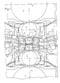
- Fig. 1 ein Walzwerk mit zwei Arbeitswalzen, zwei Zwischenwalzen und zwei Stützwalzen mit im Walzgerüst eingebauter Baueinheit im Querschnitt gemäß der Erfindung,
- Fig. 2 ein aus zwei Arbeitswalzen und zwei Stützwalzen bestehendes Walzwerk mit Bandanhebevorrichtung in Einfädel-Position gemäß der Erfindung im Querschnitt,
- Fig. 3 ein aus zwei Arbeitwalzen und zwei Stützwalzen bestehendes Walzwerk mit unterschiedlich groß ausgebildeten Arbeitswalzen gemäß der Erfindung im Querschnitt,
- Fig. 4 ein aus zwei Arbeitswalzen und zwei Stützwalzen bestehendes, in Walzen-Wechsel-Position dargestelltes Walzwerk gemäß der Erfindung im Querschnitt,
- Fig. 5 ein druckluftgesteuertes Spritzdüsenventil gemäß der Erfindung im Längsschnitt.
- 1 shows a rolling mill with two work rolls, two intermediate rolls and two backup rolls with a built-in structural unit in cross section according to the invention,
- 2 a cross-section of a rolling mill consisting of two work rolls and two backup rolls with a belt lifting device in the threading position according to the invention,
- 3 shows a cross-section of a rolling mill consisting of two work rolls and two backup rolls with work rolls of different sizes according to the invention,
- 4 shows a cross section of a rolling mill according to the invention consisting of two work rolls and two backup rolls, shown in the roll changing position,
- Fig. 5 is a compressed air-controlled spray nozzle valve according to the invention in longitudinal section.
Wie Figur 1 zeigt, besteht das Walzwerk aus zwei in einem Walzgerüst (1) übereinander angeordneten Arbeitswalzen (2, 3), Zwischenwalzen (4, 5) und Stützwalzen (6, 7). Zu beiden Seiten der Arbeitswalzen (2) und (3), und zwar ein- und auslaufseitig, sind im Walzgerüst (1) gleich ausgebildete Walzbandanhebevorrichtungen (8) mit auf den Walzspalt (9) gerichteten Bandabweisern (10), Spritzeinrichtungen (11), Ausfahrschienen (12) und Walzbandleittischen (13) angeordnet. Es handelt sich hierbei um ein Reversier-Walzwerk, bei dem die Arbeitswalzen (2, 3) je nach Walzrichtung gegenüber der vertikalen Mittellinie (14) der Zwischenwalzen (4, 5) und Stützwalzen (6, 7) in horizontaler Richtung um einen Betrag (d) nach links oder rechts verstellt, und die obere Arbeitswalze (2), die darüber angeordnete Zwischenwalze (4) und die Stützwalze (6) rechts von der Mittellinie (14) in vertikaler Richtung um einen Betrag (e), der dem Arbeitswalzspalt (9) entspricht, hälftig nach oben angehoben dargestellt sind. Die rechte Seite von Fig. 1 zeigt die Einfädelposition für das Band, die linke Seite die Betriebsstellung. Die Walzbandanhebevorrichtungen (8) mit Bandabweisern (10), Spritzeinrichtungen (11), Ausfahrschienen (12) und Walzbandleittischen (13) sind gemäß der Erfindung zu einer sehr kompakten, gut zugänglichen Baueinheit zusammengefaßt und innerhalb des Walzgerüstes (1) angeordnet. Die Walzbandanhebevorrichtungen (8) mit Bandabweisern (10) und Spritzvorrichtungen (11) sind im Walzenbiegeblock (15) integriert, der sehr vorteilhaft mit Ausnehmungen (16) versehen ist, in die die Walzenausfahrschienen (12) der an den Arbeitswalzen (2, 3) zu beiden Seiten angeordneten Einbaustücke (17) jeweils eingreifen. Die Bandanhebevorrichtungen (8) mit Bandabweisern (10) und Spritzvorrichtungen (11) bilden eine starre Einheit, die horizontal und vertikal beweglich mittels in der Zeichnung gestrichelt dargestellten, geneigt angeordneten Nuten (18) und Paßfedern (19) im Bereich der Arbeitswalzen (2, 3) durch die Walzenbiegeblöcke (15) in Kassettenausführung in der jeweils erforderlichen Position gehalten wird.As shown in FIG. 1, the rolling mill consists of two work rolls (2, 3), intermediate rolls (4, 5) and backup rolls (6, 7) arranged one above the other in a roll stand (1). On both sides of the work rolls (2) and (3), namely on the inlet and outlet sides, there are rolled strip lifting devices (8) of the same design in the roll stand (1) with strip deflectors (10), spray devices (11) directed onto the roll gap (9), Extending rails (12) and roller conveyor tables (13) are arranged. It is a reversing rolling mill, in which the work rolls (2, 3), depending on the rolling direction, with respect to the vertical center line (14) of the intermediate rolls (4, 5) and support rollers (6, 7) in the horizontal direction by an amount (d) to the left or right, and the upper work roller (2), the intermediate roller (4) arranged above and the support roller (6) to the right of the center line ( 14) in the vertical direction by an amount (e), which corresponds to the work roll gap (9), are shown half raised up. The right side of Fig. 1 shows the threading position for the tape, the left side of the operating position. The rolled strip lifting devices (8) with strip deflectors (10), spraying devices (11), extension rails (12) and rolled strip guide tables (13) are combined according to the invention into a very compact, easily accessible structural unit and arranged within the rolling stand (1). The rolled strip lifting devices (8) with strip deflectors (10) and spraying devices (11) are integrated in the roll bending block (15), which is very advantageously provided with recesses (16) into which the roll extension rails (12) on the work rolls (2, 3) engage chocks (17) on both sides. The belt lifting devices (8) with belt deflectors (10) and spraying devices (11) form a rigid unit which can be moved horizontally and vertically by means of inclined grooves (18) and feather keys (19) in the area of the work rolls (2, 3) is held in the required position by the roller bending blocks (15) in cassette design.
Durch die konträre Neigung der horizontal und vertikal beweglichen Nut-Paßfederverbindungen (18, 19) des an der oberen Arbeitswalze (2) angeordneten Walzenbiegeblockes (15) gegenüber dem an der unteren Arbeitswalze (3) angeordneten Walzenbiegeblock (15) wird vorteilhaft erreicht, daß die Position des eine starre Einheit bildenden Multi-Funktions-Blockes eine Funktion von der Position des jeweils oberen und unteren Walzenbiegeblocks (15) ist. Die Position der Walzenbiegeblöcke (15) ist - bedingt durch die Kassettenbauart - wiederum über die Einbaustücke (17) von der horizontalen und vertikalen Lage der Arbeitswalzen (2, 3) im Walzgerüst (1) abhängig.Due to the opposite inclination of the horizontally and vertically movable groove-key connections (18, 19) of the the upper work roll (2) arranged roll bending block (15) in relation to the roll bending block (15) arranged on the lower work roll (3) is advantageously achieved that the position of the multi-function block forming a rigid unit is a function of the position of the upper one and lower roll bending block (15). The position of the roller bending blocks (15) - due to the type of cassette - in turn depends on the chocks (17) of the horizontal and vertical position of the work rolls (2, 3) in the roll stand (1).
Dieser in Figur 1 dargestellte und erfindungsgemäß ausgebildete Multi-Funktions-Block setzt jedoch den Einsatz von Arbeitswalzen voraus, die untereinander nur verhältnismäßig geringe Durchmesser-Differenzen (140 - 160 mm) aufweisen. Falls jedoch Arbeitswalzen mit größeren Walzen-Durchmesser-Differenzen bei einem Walzwerk zum Einsatz kommen sollen, so kann dies durch Austausch der horizontalen Schleißleisten der an den Arbeitswalzen (2, 3) angreifenden Einbaustücke (17) leicht bewerkstelligt werden. Auch die in der Walzbandebene verlaufenden Walzbandleittische (13) können in ihrer Länge durch montierbare Winkelstücke (20) verändert werden.However, this multi-function block shown in FIG. 1 and designed in accordance with the invention requires the use of work rolls which have only relatively small diameter differences (140-160 mm). However, if work rolls with larger roll diameter differences are to be used in a rolling mill, this can be easily accomplished by replacing the horizontal wear strips of the chocks (17) engaging the work rolls (2, 3). The length of the strip conveyor tables (13) running in the plane of the strip can also be changed in length by mountable angle pieces (20).
Im übrigen ermöglicht die erfindungsgemäße Ausgestaltung des Walzwerkes auch sehr vorteilhaft die Anordnung von Rollen (21) zur Führung und Beruhigung des Walzbandes (22) sowie von hydraulischen Verstelleinrichtungen (23) für die Rollen (21), Walzenleittische (13) etc. innerhalb des Walzgerüstes und zwar ebenfalls in der Nähe des Walzspaltes (9).In addition, the inventive design of the rolling mill also very advantageously allows the arrangement of rollers (21) for guiding and calming the rolling strip (22) and hydraulic adjustment devices (23) for the rollers (21), roller guide tables (13) etc. within the roll stand also in the vicinity of the roll gap (9).
Vor Inbetriebnahme des Walzwerkes gemäß der Erfindung wird der gewünschte Abstand zwischen den Bandabweisern (10) und den Ballen bzw. der Oberfläche der Arbeitswalzen (2, 3) bei maximalen Walzendurchmesser und geschlossenem Walzspalt (9) ohne Walzgut festgelegt. Werden jedoch die Arbeitswalzendurchmesser, bedingt durch den Abschliff, im Betrieb des Walzwerkes kleiner, so wird im Walzbetrieb auch der Abstand des an der oberen Arbeitswalze (2) angeordneten Walzenbiegeblockes (15) zum unteren Walzenbiegeblock (15) der Arbeitswalze (3) ensprechend kleiner. Durch die Neigung der Nuten (18) und Paßfedern (19) wird der Multi-Funktions-Block und damit die Bandabweiser (10) in Richtung auf den Walzspalt (9) hinbewegt.Before the rolling mill according to the invention is put into operation, the desired distance between the belt deflectors (10) and the bales or the surface of the work rolls (2, 3) is determined with the maximum roll diameter and closed roll gap (9) without rolling stock. However, if the work roll diameter becomes smaller during operation of the rolling mill due to the grinding, the distance between the roll bending block (15) arranged on the upper work roll (2) and the lower roll bending block (15) of the work roll (3) will also become correspondingly smaller in the rolling operation. Due to the inclination of the grooves (18) and feather keys (19), the multi-function block and thus the strip deflectors (10) are moved in the direction of the roll gap (9).
Wie insbesondere aus dem in Figur 2 dargestellten Ausführungsbeispiel mit den zwei Arbeitswalzen (24, 25) und den Zwischen- bzw. Stützwalzen (26, 27) gut zu ersehen ist, bleibt bei einer bestimmten Neigung der Nut (28) /Paßfeder (29) -Anordnungen der Abstand (30) zwischen den Oberflächen der Arbeitswalzen (24, 25) und den Bandabweisern (31) nahezu konstant, d. h. der Walzenabschliff wird vollständig und automatisch kompensiert. Das Walzband (32) berührt die untere Arbeitswalze (25) und wird optimal geführt. Der Abstand (30) zwischen den Oberflächen der Arbeitswalzen (24, 25) und den Bandabweisern (31) wird zwar auch von dem im Betrieb des Walzwerkes zwischen den Arbeitswalzen befindlichen Walzgut beeinflußt; jedoch ist dies ohne Bedeutung, da bei dünnen Bändern von beispielsweise 0,2 mm die Abstandsdifferenz vernachlässigbar ist, und bei dicken Bändern von beispielsweise 3 mm die Abstandsdifferenz noch wesentlich unterhalb der Banddicke liegt. Ein dickes Band läuft somit völlig problemlos, während bei einem dünnen Band sehr vorteilhaft der Bandabweiser (31) für den optimalen Lauf des Walzbandes (32) sorgt. Damit der Anfang des Walzbandes beim Einführen in den offenen Walzspalt (33) nicht stumpf gegen die untere Arbeitswalze (25) oder gegen die obere Arbeitswalze (24) stößt, wird die obere Arbeitswalze (24) nach oben verfahren. Dabei machen die Bandabweiser (31) der Walzbandanhebevorrichtung (34) eine Relativbewegung in vertikaler Richtung nach oben, wobei sie sich auf Grund der geneigten Nut (28) /Paßfeder (29) - Verbindung in horizontaler Richtung von den Arbeitswalzen (24, 25) entfernen. Je nach Höhe des offenen Walzspaltes (33) können die Bandabweiser (31) knapp unterhalb bis über das Niveau des Ballens der Arbeitswalze gefahren werden.As can be seen particularly well from the exemplary embodiment shown in FIG. 2 with the two work rolls (24, 25) and the intermediate or support rolls (26, 27), the groove (28) / feather key (29) remains at a certain inclination. -Arrangements of the distance (30) between the surfaces of the work rolls (24, 25) and the belt deflectors (31) almost constant, ie the roll grinding is completely and automatically compensated. The rolled strip (32) touches the lower work roll (25) and is guided optimally. The distance (30) between the surfaces of the work rolls (24, 25) and the strip deflectors (31) is also influenced by the rolling stock located between the work rolls during operation of the rolling mill; however, this is of no importance, since the distance difference is negligible for thin strips of, for example, 0.2 mm, and for thick strips of, for example, 3 mm, the distance difference is still substantially below the strip thickness. A thick strip thus runs without any problems, while in the case of a thin strip, the strip deflector (31) very advantageously ensures that the rolled strip (32) runs optimally. The upper work roll (24) is moved upwards so that the beginning of the rolled strip does not butt against the lower work roll (25) or against the upper work roll (24) when it is introduced into the open roll gap (33). The strip deflectors (31) of the rolled strip lifting device (34) make a relative movement in the vertical direction upwards, and due to the inclined groove (28) / feather key (29) connection they move away from the work rolls (24, 25) in the horizontal direction . Depending on the height of the open roll gap (33), the belt deflectors (31) can be moved just below to the level of the bale of the work roll.
Figur 3 zeigt ein Walzwerk, bei dem die obere Arbeitswalze (35) einen bedeutend geringeren Durchmesser aufweist als die untere Arbeitswalze (36). Sie stellt eine Extrem-Kombination dar, bei der der jeweils obere Bandabweiser (38) gegenüber dem unteren Bandabweiser (38) einen größeren Abstand von der Arbeitswalze (35) aufweist. Eine optimale Anpassung der an der Walzbandanhebevorrichtung (37) angeordneten Bandabweiser (38) an diese unterschiedlich groß dimensionierten Arbeitswalzen (35, 36) kann auch hierbei durch Paßfederverstellung, Schleißleistenveränderung oder aber auch durch Zweiteilung bzw. Trennung der Walzbandanhebevorrichtung (37) und zwar in einen oberen Teil (39) und einen unteren Teil (40) sehr vorteilhaft erreicht werden.Figure 3 shows a rolling mill in which the upper work roll (35) has a significantly smaller diameter than the lower work roll (36). It represents an extreme combination in which the respective upper belt deflector (38) is at a greater distance from the work roll (35) compared to the lower belt deflector (38). An optimal adaptation of the strip deflectors (38) arranged on the rolled strip lifting device (37) to these differently sized work rolls (35, 36) can also can be achieved very advantageously by adjusting the feather key, changing the wear strip or by dividing or separating the roller belt lifting device (37) into an upper part (39) and a lower part (40).
Bei dem in Figur 4 dargestellten Walzwerk befinden sich die Arbeitswalzen (41, 42) in Walzenwechsel-Position. In dieser Position nehmen die Arbeitswalzen (41, 42) ihren größtmöglichen vertikalen Abstand voneinander ein, und der Multi-Funktions-Block (43) befindet sich in der entferntesten horizontalen Position von den Arbeitswalzen (41, 42). In dieser Position bilden die zu beiden Seiten der Arbeitswalzen (41, 42) angeordneten Multi-Funktions-Blöcke (43) durchgehende Schienenspuren (44) für die Einbaustücke (45).In the rolling mill shown in FIG. 4, the work rolls (41, 42) are in the roll changing position. In this position, the work rolls (41, 42) are spaced as far apart from each other as possible, and the multi-function block (43) is in the farthest horizontal position from the work rolls (41, 42). In this position, the multi-function blocks (43) arranged on both sides of the work rolls (41, 42) form continuous rail tracks (44) for the chocks (45).
Bei dem erfindungsgemäß ausgebildeten Walzwerk kann es besonders zweckmäßig sein, als Spritzeinrichtungen (11), jeweils ein Sprühaggregat einzusetzen, das gemäß Figur 5 aus einem druckluftgesteuerten, federbelasteten Düsenventil (46) besteht. Bei diesem Düsenventil (46) wird vorzugsweise Luft in Pfeilrichtung (47) axial in den Düsenkörper (48) unter Druck geführt, um das Ventil zu schließen, wobei in druckloser Stellung die Flüssigkeit (z. B. Wasser) durch eine Zuleitung unter Druck in den Ringraum (49) eingeführt und von dort durch die Öffnungen (50) im Düsenkörper (48) in die Düsenaustrittsöffnung (51) gelangt und in fein verteilter Form auf die jeweilige Walze des Walzwerkes auftrifft. Der Wasserdruck auf den Kegel (52) bewirkt dessen Rückwärtsbewegung gegen den Druck der Feder (53) und gibt damit den Weg zur Öffnung (51) frei. Zum Zwecke einer ausreichenden Walzenkühlung oder -schmierung können mehrere derartig ausgebildete Düsenventile (46) sowohl nebeneinander als auch in Reihen übereinander eingesetzt werden.In the rolling mill designed according to the invention, it may be particularly expedient to use a spray unit as the spray device (11), which according to FIG. 5 consists of a compressed air-controlled, spring-loaded nozzle valve (46). In this nozzle valve (46), air is preferably led axially into the nozzle body (48) under pressure in the direction of the arrow (47) under pressure in order to close the valve, the liquid (for example water) in a depressurized position through a supply line under pressure introduced the annular space (49) and from there through the openings (50) in the nozzle body (48) into the nozzle outlet opening (51) and in finely divided form on the respective Roll of the rolling mill hits. The water pressure on the cone (52) causes it to move backwards against the pressure of the spring (53) and thus clears the way to the opening (51). For the purpose of sufficient roller cooling or lubrication, several nozzle valves (46) designed in this way can be used both next to one another and in rows one above the other.
Der sehr stabile Multi-Funktions-Block gemäß der Erfindung ermöglicht es, die Bandabweiser mit Abstand der Düsen auf Düsenbreite auszuklinken, so daß in diesen dadurch enstehenden Ausnehmungen die Düsen, und zwar auch vorgesteuerte Düsen angeordnet werden können, die direkt in den Walzspalt spritzen. Die Höhe des Multi-Funktions-Blockes erlaubt auch sehr vorteilhaft die Anordnung von mehreren zusätzlichen Reihen dieser in Figur 5 dargestellten Düsen. Darüberhinaus besteht bei dem erfindungsgemäß ausgebildeten Walzgerüst auch die Möglichkeit der Anordnung von Meßträgern, Sensoren usw. nahe den Walzen, und zwar in den Bandabweisern oder an anderer Stelle der Walzbandanhebevorrichtungen.The very stable multi-function block according to the invention makes it possible to release the band deflectors at a distance from the nozzles to the width of the nozzle, so that the resulting nozzles, including piloted nozzles, can be arranged which spray directly into the roll gap. The height of the multi-function block also very advantageously allows the arrangement of several additional rows of these nozzles shown in FIG. 5. In addition, in the roll stand designed according to the invention, there is also the possibility of arranging measuring carriers, sensors, etc. near the rolls, specifically in the strip deflectors or elsewhere in the roll strip lifting devices.
Die erfindungsgemäßen Maßnahmen sind nicht auf die in den Zeichnungsfiguren dargestellten Ausführungsbeispiele beschränkt. So kann beispielsweise, ohne den Rahmen der Erfindung zu verlassen, der Multi- Funktionsblock in beliebiger Weise geformt sein. Die jeweilige konstruktive Ausgestaltung ist in Anpassung an die spezielle Verwendung der Vorrichtung dem Fachmann anheimgestellt.The measures according to the invention are not limited to the exemplary embodiments shown in the drawing figures. For example, without departing from the scope of the invention, the multi-function block can be shaped in any way. The respective structural design is left to the person skilled in the art in adaptation to the special use of the device.
Claims (7)
Applications Claiming Priority (2)
| Application Number | Priority Date | Filing Date | Title |
|---|---|---|---|
| DE3822821A DE3822821A1 (en) | 1988-07-06 | 1988-07-06 | ROLLING MILL FOR PRODUCING A ROLLING GOOD |
| DE3822821 | 1988-07-06 |
Publications (2)
| Publication Number | Publication Date |
|---|---|
| EP0349840A2 true EP0349840A2 (en) | 1990-01-10 |
| EP0349840A3 EP0349840A3 (en) | 1990-10-10 |
Family
ID=6358053
Family Applications (1)
| Application Number | Title | Priority Date | Filing Date |
|---|---|---|---|
| EP19890111347 Withdrawn EP0349840A3 (en) | 1988-07-06 | 1989-06-22 | Rolling mill for the production of a rolling stock |
Country Status (4)
| Country | Link |
|---|---|
| US (1) | US4974437A (en) |
| EP (1) | EP0349840A3 (en) |
| JP (1) | JPH0255611A (en) |
| DE (1) | DE3822821A1 (en) |
Cited By (1)
| Publication number | Priority date | Publication date | Assignee | Title |
|---|---|---|---|---|
| WO2005118172A1 (en) * | 2004-05-26 | 2005-12-15 | Sms Demag Ag | Method and device for mounting and functional verification of roll fittings in roll stands such as rolling trains in tandem |
Families Citing this family (7)
| Publication number | Priority date | Publication date | Assignee | Title |
|---|---|---|---|---|
| US5535599A (en) * | 1994-09-07 | 1996-07-16 | Ipsco Enterprises Inc. | Modular table roll with water bath |
| DE19508972A1 (en) * | 1995-03-13 | 1996-09-19 | Schloemann Siemag Ag | Device for the automatic positioning of roll stands with caliber rolls and these upstream rolling beams and rolling fittings on the center of the roll |
| IT1315084B1 (en) * | 2000-04-20 | 2003-02-03 | Danieli Off Mecc | COOLING DEVICE FOR ROLLING RINGS AND RELATED PROCEDURE. |
| JP4556856B2 (en) * | 2005-12-02 | 2010-10-06 | 株式会社Ihi | Rolling equipment |
| DE102007048747A1 (en) * | 2007-09-10 | 2009-03-12 | Sms Demag Ag | Device for adjusting the distance of the scraper chisel |
| KR101530514B1 (en) * | 2011-04-12 | 2015-06-22 | 지멘스 피엘씨 | Roll stripper device and method |
| CN115740042A (en) * | 2022-11-07 | 2023-03-07 | 中冶南方工程技术有限公司 | Strip steel clamping and lifting device for cold rolling mill |
Family Cites Families (9)
| Publication number | Priority date | Publication date | Assignee | Title |
|---|---|---|---|---|
| US2907527A (en) * | 1956-04-10 | 1959-10-06 | Thompson Ramo Wooldridge Inc | Nozzle |
| US3513680A (en) * | 1967-09-25 | 1970-05-26 | Siegener Maschinenbau Gmbh | Rolled stock stripper on roll stands in particular,universal girder stands |
| DE2356785C3 (en) * | 1973-11-14 | 1981-01-22 | Schloemann-Siemag Ag, 4000 Duesseldorf | Rolling armature with upper and lower rolling stock guides |
| US3864954A (en) * | 1973-12-04 | 1975-02-11 | Blaw Knox Foundry Mill Machine | Roll changers |
| KR880000759B1 (en) * | 1978-11-03 | 1988-05-06 | 제이. 알. 바췔러 | A cooling apparatus of steel strip |
| EP0059417B1 (en) * | 1981-02-28 | 1985-01-02 | Sms Schloemann-Siemag Aktiengesellschaft | Roll stand |
| JPS57199505A (en) * | 1981-06-03 | 1982-12-07 | Hitachi Ltd | Work roll moving type rolling mill |
| EP0205295B1 (en) * | 1985-06-10 | 1990-12-05 | DAVY McKEE (POOLE) LIMITED | Improvements relating to the lubrication of rolling mills |
| US4706485A (en) * | 1986-12-15 | 1987-11-17 | Morgan Construction Company | Carrier module |
-
1988
- 1988-07-06 DE DE3822821A patent/DE3822821A1/en not_active Withdrawn
-
1989
- 1989-06-22 EP EP19890111347 patent/EP0349840A3/en not_active Withdrawn
- 1989-06-28 JP JP1164087A patent/JPH0255611A/en active Pending
- 1989-07-06 US US07/375,969 patent/US4974437A/en not_active Expired - Fee Related
Cited By (1)
| Publication number | Priority date | Publication date | Assignee | Title |
|---|---|---|---|---|
| WO2005118172A1 (en) * | 2004-05-26 | 2005-12-15 | Sms Demag Ag | Method and device for mounting and functional verification of roll fittings in roll stands such as rolling trains in tandem |
Also Published As
| Publication number | Publication date |
|---|---|
| JPH0255611A (en) | 1990-02-26 |
| EP0349840A3 (en) | 1990-10-10 |
| US4974437A (en) | 1990-12-04 |
| DE3822821A1 (en) | 1990-01-18 |
Similar Documents
| Publication | Publication Date | Title |
|---|---|---|
| EP1142652A2 (en) | Roll cooling and/or lubricating device for cold strip rolling mills, in particular fine strip and foil rolling mills | |
| DE1232111B (en) | Device for cleaning a filter belt | |
| DE19649073C2 (en) | Device for cooling extruded profiles | |
| DE102007010375A1 (en) | Device for cooling a metal strip | |
| EP1900449B1 (en) | Spray header of a hydraulic descaling facility and method for operating such a spray header | |
| EP0349840A2 (en) | Rolling mill for the production of a rolling stock | |
| EP3251762B1 (en) | Lubricating device for applying a lubricant when rolling a product to be rolled | |
| DE3238938C2 (en) | ||
| DE3331055C2 (en) | Roll stand with axially movable work rolls | |
| EP1492634B1 (en) | Device for cooling rolling stock within the cooling stretch of a rolling mill | |
| DE3431316C2 (en) | Guide device on the casting belts of a double-belt continuous casting mold | |
| DE3324562C2 (en) | Six-roll stand | |
| DE2547416A1 (en) | DEVICE FOR COOLING TAPE MATERIAL | |
| EP0337145A2 (en) | Device for hydrostatically supporting rolls of a rolling mill | |
| EP3419778A1 (en) | Nozzle row arrangement and nozzle field for installing in a roller gap between two strand guide rollers | |
| DE60111993T2 (en) | Apparatus and method for cooling rolling rings | |
| EP0650776A1 (en) | Device for cooling rolled strips | |
| DE10295854B4 (en) | Apparatus for heat treatment and hydraulic conveyance of rolling stock | |
| DE3918242A1 (en) | Spacers esp. for working rollers in quatro-rolling stand - are freely movable in guide grooves in roller installation parts to facilitate roller replacement without damage to new rollers | |
| DE2426828A1 (en) | DEVICE FOR COOLING BAR MATERIAL | |
| WO2004105981A2 (en) | Casting ladle slide-gate | |
| DE19960593C2 (en) | Device for cooling a cast metal strand | |
| DE4228164B4 (en) | Device for distance positioning of bearing in bearing chocks roller pairs | |
| DE1452935A1 (en) | Plate leveler | |
| EP0492227A1 (en) | Device for cooling the pressing tools of a pressing machine and methods for its operation |
Legal Events
| Date | Code | Title | Description |
|---|---|---|---|
| PUAI | Public reference made under article 153(3) epc to a published international application that has entered the european phase |
Free format text: ORIGINAL CODE: 0009012 |
|
| 17P | Request for examination filed |
Effective date: 19890714 |
|
| AK | Designated contracting states |
Kind code of ref document: A2 Designated state(s): AT DE ES FR GB IT |
|
| PUAL | Search report despatched |
Free format text: ORIGINAL CODE: 0009013 |
|
| AK | Designated contracting states |
Kind code of ref document: A3 Designated state(s): AT DE ES FR GB IT |
|
| STAA | Information on the status of an ep patent application or granted ep patent |
Free format text: STATUS: THE APPLICATION IS DEEMED TO BE WITHDRAWN |
|
| 18D | Application deemed to be withdrawn |
Effective date: 19920102 |