EP0349526A2 - Power-driven hand tool - Google Patents
Power-driven hand tool Download PDFInfo
- Publication number
- EP0349526A2 EP0349526A2 EP89890177A EP89890177A EP0349526A2 EP 0349526 A2 EP0349526 A2 EP 0349526A2 EP 89890177 A EP89890177 A EP 89890177A EP 89890177 A EP89890177 A EP 89890177A EP 0349526 A2 EP0349526 A2 EP 0349526A2
- Authority
- EP
- European Patent Office
- Prior art keywords
- hand tool
- tool according
- gas
- control valve
- expansion chamber
- Prior art date
- Legal status (The legal status is an assumption and is not a legal conclusion. Google has not performed a legal analysis and makes no representation as to the accuracy of the status listed.)
- Withdrawn
Links
Images


Classifications
-
- B—PERFORMING OPERATIONS; TRANSPORTING
- B25—HAND TOOLS; PORTABLE POWER-DRIVEN TOOLS; MANIPULATORS
- B25C—HAND-HELD NAILING OR STAPLING TOOLS; MANUALLY OPERATED PORTABLE STAPLING TOOLS
- B25C1/00—Hand-held nailing tools; Nail feeding devices
- B25C1/08—Hand-held nailing tools; Nail feeding devices operated by combustion pressure
Definitions
- the invention relates to a power-operated hand tool, in which a compressed gas-operated piston can be moved in a cylinder and the tool can thereby be actuated, the actuation of the cylinder being controllable by means of a valve.
- the piston is pressurized by means of compressed air or another compressed gas, the actuation of the piston being achieved solely by the pressure of the applied gas.
- Such a design has the disadvantage that the force of the tool depends on the pressure of the compressed gas source, i.e. that as the pressure decreases, the power of the tool also decreases.
- explosion capsules are used in the manner of cartridges, which then actuate the tool.
- Such devices are known for setting bolts in concrete. They have the disadvantage that extensive manipulation is necessary before each shot, namely opening the device, inserting the explosion capsule, inserting the bolt to be inserted, locking the device and then attaching it to the place where the bolt is to be inserted. Only then can the explosion capsule be fired to place the bolt.
- the invention has for its object to provide a hand tool of the type mentioned, in which a rapid succession of operations is possible, wherein also the piston is always subjected to almost the same pressure.
- this object is achieved in that an ignition device is arranged in the gas-loaded expansion chamber of the cylinder, an ignitable gas mixture is used to act on the expansion chamber and a return spring is provided for returning the piston to its initial position.
- an ignition device is arranged in the gas-loaded expansion chamber of the cylinder, an ignitable gas mixture is used to act on the expansion chamber and a return spring is provided for returning the piston to its initial position.
- the expansion chamber can be preceded by a mixing chamber for mixing the ignitable gas with air, the control valve being arranged between the mixing chamber and the expansion chamber.
- the connection between expansion chamber and mixing chamber and the exhaust can be provided in the end face of the expansion chamber, the control valve being designed as a one-piece, flat part which covers both the inlet from the mixing chamber and the exhaust. This ensures that when the ignitable gas flows in, the burned gas is simultaneously discharged through the exhaust, so that each up and down movement of the tool represents a work cycle.
- the part forming the control valve can have on its underside a flow body reaching into the mixing chamber for swirling the gas-air mixture.
- the part forming the control valve can be connected to a bumper which extends perpendicular to the plane of the part and on which the return spring for the valve acts.
- the end of the bumper facing away from the part forming the control valve can be designed as an impact piece for striking the, preferably piezoelectrically operating ignition device, so that when the control valve is returned to its closed position, the ignition takes place simultaneously, so that no separate ignition of the gas Air mixture is necessary.
- This can be done by the A laterally arranged bumper, preferably flange-like, can be arranged to engage the trigger device, so that the essential movements for the work, namely filling the expansion space, closing the control valve and igniting the gas mixture can be carried out in one operation.
- the trigger device can have a trigger tap, the pivot axis of which engages via an elongated hole on the tap which, when the tap is relaxed, runs in the direction of the rear of the projection of the bumper.
- the tap is in the position prepared for actuation, so that when the tap is actuated, the part intended for engagement behind the flange is automatically moved into the actuation position.
- the tap can be returned via a spring to its position, which does not yet engage behind the projection, so that the tap automatically returns to its starting position.
- the tap can be prevented from engaging behind the projection by a safety lock.
- an impact rod of a gas inflow control valve can additionally be struck by means of the striking piece.
- the gas inflow control valve can have a plug connected to the end of the actuating rod facing away from the striker for the closure of the outlet opening of a gas connection fitting.
- a piston 2 is sealingly guided.
- An expansion space 3 is provided below the piston and is closed off at the lower end by a base 4.
- the piston 2 is loaded into its retracted position by means of a return spring 5. In this position, the piston 2 bears against a stop ring 6 and thus delimits the lower part of the expansion space 3.
- the expansion space 3 is preceded by a mixing chamber 7 which is connected to the expansion space 3 via a passage 8 provided in the base 4.
- a passage 8 provided in the base 4.
- there are also two exhaust passages 9 (see FIG. 2) which lead laterally outwards via channels 10.
- the passage 8 and the exhaust passages 9 can be closed by a valve plate 11, which in the present case is of three-wing design. Of course, a circular valve plate could also be provided.
- the outline of the valve plate depends only on the configuration and arrangement of the passages in the bottom 4.
- the valve plate 11 is fixedly connected to a plunger 12 which is provided with a striking head 13 at the lower end.
- This striking head which is firmly connected to the plunger 12, is designed here as a sleeve, which surrounds the plunger over a partial area.
- a return spring 14 is provided between the plunger 12 and the sleeve part of the striking head 13, which loads the plunger and thus the valve plate in the sense of closing the valve.
- an outwardly projecting flange 15 is provided, which serves to engage a trigger valve 16.
- the trigger valve 16 is pivotally mounted about a bolt 17, on which it engages via an elongated hole 18.
- This slot 18 runs parallel to the feed direction of the trigger for engagement, the tip 16 'comes to lie behind the flange 15 of the striking head 13. 1, the faucet 16 is secured against engagement by means of a slide 19, wherein it is loaded by means of a spring 20 in the sense of pivoting into the engaged position.
- a piezoelectric ignition device 21 which is connected 22 to a spark plug provided in the expansion space 3.
- This gas inflow control valve 24 is designed as a plug, which is designed for contact with the end face of the gas connection fitting 25 for the purpose of closing off the outlet bore 26.
- the valve plate 11 has on its underside a flow body 27 which extends into the passage 8 and which serves to swirl the escaping gas-air mixture from the mixing chamber 7.
- a cutting knife 28 is provided which points towards the upper end of the cylinder 1 and which passes through the cover 29 of the cylinder.
- a knife guide 30 is provided which has a recess 31 extending into the movement path of the cutting edge 28 'of the knife 28, with which the knife guide forms a hook in which the vine to be cut is inserted.
- a stop 32 made of elastic material is provided for the piston.
- the safety slide 19 When starting up the device according to the invention, the safety slide 19 is retracted into the position shown in Fig. 3, whereby due to the spring 20 of the faucet 16 is pivoted into its operational position, in which the tip 16 'under the flange 15 of the striking head 13.
- the spring 20 is additionally supported on the support bolt 33, which is adjacent to the bolt 17.
- the trigger valve When the trigger valve is actuated, the latter slides along the elongated hole 18 on the bolt 17 in the direction of the sleeve part of the striking head 13, namely until the bolt 17 rests on the rear end of the elongated hole 18. In this position, the cock 16 engages with its tip 16 'under the flange 15 (see this position in Fig. 4).
- the actuating rod 23 is also pushed down, as a result of which the stopper of the gas inflow control valve 24 closes the gas outlet opening 26 of the gas connection fitting 25.
- the piston is suddenly moved upwards, whereby the knife 28 with the cutting edge 28 'is moved over the recess 31 of the knife guide, thereby cutting off the vine inserted in the recess 31.
- the piston is moved so far up in the cylinder that at its rear it opens compensation openings 34 in the piston wall, through which the main quantity passes of the expanded gas can escape.
- the piston is then moved back into its starting position due to the return spring 5, which is shown in FIG. 8. If the trigger 16 is now released, then it pivots back into its starting position shown in FIG. 3 due to the spring 20.
- the control of the gas supply to the mixing chamber takes place in that the actuating rod 23 is released by lifting the striking head 13, so that the plug 24 of the gas inflow control valve is moved upward due to the gas pressure, which causes the gas outlet opening of the gas connection fitting 25 to open. As a result, ignitable gas can then flow into the mixing chamber 7 in the appropriate amount, into which air can simultaneously flow through an opening 35.
- the trigger 16 is secured against unintentional actuation by moving the slide 19 into the position shown in FIG. 1.
- the same drive device can be used to operate a nail driving device or a bolt setting device or another similar device.
Landscapes
- Engineering & Computer Science (AREA)
- Chemical & Material Sciences (AREA)
- Combustion & Propulsion (AREA)
- Mechanical Engineering (AREA)
- Percussive Tools And Related Accessories (AREA)
- Portable Nailing Machines And Staplers (AREA)
Abstract
Kraftbetriebenes Handwerkzeug, bei welchem ein druckgasbetriebener Kolben in einem Zylinder bewegbar und dadurch das Werkzeug betätigbar ist, wobei die Beaufschlagung des Zylinders mittels eines Ventils steuerbar ist, und wobei in der gasbeaufschlagten Expansionskammer (3) des Zylinders (1) eine Zündeinrichtung (22) angeordnet, zur Beaufschlagung der Expansionskammer (3) ein zündfähiges Gasgemisch eingesetzt und zur Rückführung des Kolbens (2) in seine Ausgangsstellung eine Rückstellfeder (5) vorgesehen ist.Power-operated hand tool, in which a pressurized gas-operated piston is movable in a cylinder and the tool can thereby be actuated, the action on the cylinder being controllable by means of a valve, and an ignition device (22) being arranged in the gas-charged expansion chamber (3) of the cylinder (1) , an ignitable gas mixture is used to act on the expansion chamber (3) and a return spring (5) is provided to return the piston (2) to its initial position.
Description
Die Erfindung bezieht sich auf ein kraftbetriebenes Handwerkzeug, bei welchem ein druckgasbetriebener Kolben in einem Zylinder bewegbar und dadurch das Werkzeug betätigbar ist, wobei die Beaufschlagung des Zylinders mittels eines Ventils steuerbar ist.The invention relates to a power-operated hand tool, in which a compressed gas-operated piston can be moved in a cylinder and the tool can thereby be actuated, the actuation of the cylinder being controllable by means of a valve.
Bei bekannten Ausbildungen dieser Art erfolgt die Druckbeaufschlagung des Kolbens mittels Druckluft oder eines sonstigen Druckgases, wobei die Betätigung des Kolbens einzig und allein durch den Druck des aufgebrachten Gases erzielt wird. Eine solche Ausbildung hat den Nachteil, daß die Kraft des Werkzeuges von dem Druck der Druckgasquelle abhängig ist, d.h. daß bei abnehmendem Druck auch die Kraft des Werkzeuges abnimmt.In known designs of this type, the piston is pressurized by means of compressed air or another compressed gas, the actuation of the piston being achieved solely by the pressure of the applied gas. Such a design has the disadvantage that the force of the tool depends on the pressure of the compressed gas source, i.e. that as the pressure decreases, the power of the tool also decreases.
Weiters sind kraftbetriebene Handwerkzeuge bekannt bei welchen Explosionskapseln nach Art von Patronen eingesetzt werden, die dann das Werkzeug betätigen. Derartige Apparate sind zum Setzen von Bolzen in Beton bekannt. Sie haben dabei den Nachteil, daß vor jedem Schuß ein umfangreiches Manipulieren notwendig ist, nämlich öffnen des Gerätes, Einsetzen der Explosionskapsel, Einsetzen des zu setzenden Bolzens, Abschließen des Gerätes und anschließendes Ansetzen an den Ort, wo der Bolzen zu setzen ist. Erst dann kann die Zündung der Explosionskapsel erfolgen, um den Bolzen zu setzen.Furthermore, power-operated hand tools are known in which explosion capsules are used in the manner of cartridges, which then actuate the tool. Such devices are known for setting bolts in concrete. They have the disadvantage that extensive manipulation is necessary before each shot, namely opening the device, inserting the explosion capsule, inserting the bolt to be inserted, locking the device and then attaching it to the place where the bolt is to be inserted. Only then can the explosion capsule be fired to place the bolt.
Der Erfindung liegt die Aufgabe zugrunde, ein Handwerkzeug der eingangs genannten Art zu schaffen, bei welchem eine rasche Aufeinanderfolge von Betätigungen ermöglicht ist, wobei zudem der Kolben immer mit nahezu dem gleichen Druck beaufschlagt wird.The invention has for its object to provide a hand tool of the type mentioned, in which a rapid succession of operations is possible, wherein also the piston is always subjected to almost the same pressure.
Erfindungsgemäß wird diese Aufgabe dadurch gelöst, daß in der gasbeaufschlagten Expansionskammer des Zylinders eine Zündeinrichtung angeordnet, zur Beaufschlagung der Expansionskammer ein zündfähiges Gasgemisch eingesetzt und zur Rückführung des Kolbens in seine Ausgangsstellung eine Rückstellfeder vorgesehen ist. Dadurch wird erreicht, daß durch Zündung des Gemisches, welches in der Regel immer gleichmäßig von einer Gasquelle gespeist wird, immer der gleiche Druck innerhalb der Expansionskammer auftritt, so daß der Kolben, und damit das Werkzeug, immer mit nahezu der gleichen Kraft arbeitet. Außerdem ist die Handhabung sehr einfach, da das Füllen der Kammer immer unmittelbar nach der Zündung bereits erfolgen kann, so daß keine umfangreichen Manipulationen und dadurch Stillstände beim Gebrauch des kraftbetriebenen Handwerkzeuges auftreten.According to the invention this object is achieved in that an ignition device is arranged in the gas-loaded expansion chamber of the cylinder, an ignitable gas mixture is used to act on the expansion chamber and a return spring is provided for returning the piston to its initial position. This ensures that the ignition of the mixture, which is generally always fed uniformly from a gas source, always the same pressure occurs within the expansion chamber so that the piston, and thus the tool, always works with almost the same force. In addition, handling is very simple, since the chamber can always be filled immediately after ignition, so that extensive manipulations and therefore standstills do not occur when using the power-operated hand tool.
Vorteilhafterweise kann der Expansionskammer eine Mischkammer zur Mischung des zündfähigen Gases mit Luft vorgeschaltet sein, wobei das Steuerventil zwischen Mischkammer und Expansionskammer angeordnet ist. Dies hat die Wirkung, daß bereits ein im optimalen Verhältnis mit Sauerstoff gemischtes, zündfähiges Gas in die Expansionskammer eingebracht wird, wobei über das Steuerventil zudem die Menge des eingebrachten zündfähigen Gases genau steuerbar ist. Dabei kann die Verbindung zwischen Expansionskammer und Mischkammer sowie der Auspuff in der Stirnfläche der Expansionskammer vorgesehen sein, wobei das Steuerventil als einstückiger, ebener Teil ausgebildet ist, welcher sowohl den Einlaß aus der Mischkammer als auch den Auspuff abdeckt. Dadurch wird erreicht, daß beim Einströmen des zündfähigen Gases gleichzeitig das verbrannte Gas durch den Auspuff ausgetragen wird, so daß jede Auf- und Abbewegung des Werkzeuges einen Arbeitstakt darstellt. Für eine besonders gute Verteilung des zündfähigen Gases kann der das Steuerventil bildende Teil an seiner Unterseite einen bis in die Mischkammer reichenden Strömungskörper zur Vewirbelung des Gas-Luft-Gemisches aufweisen.Advantageously, the expansion chamber can be preceded by a mixing chamber for mixing the ignitable gas with air, the control valve being arranged between the mixing chamber and the expansion chamber. This has the effect that an ignitable gas mixed with oxygen in an optimal ratio is already introduced into the expansion chamber, the amount of the ignitable gas introduced can also be precisely controlled via the control valve. The connection between expansion chamber and mixing chamber and the exhaust can be provided in the end face of the expansion chamber, the control valve being designed as a one-piece, flat part which covers both the inlet from the mixing chamber and the exhaust. This ensures that when the ignitable gas flows in, the burned gas is simultaneously discharged through the exhaust, so that each up and down movement of the tool represents a work cycle. For a particularly good distribution of the ignitable gas, the part forming the control valve can have on its underside a flow body reaching into the mixing chamber for swirling the gas-air mixture.
Für die Betätigung kann der das Steuerventil bildende Teil mit einer senkrecht zur Ebene des Teiles verlaufenden Stoßstange verbunden sein, an welcher die Rückstellfeder für das Ventil angreift. Dabei kann das dem das Steuerventil bildenden Teil abgewandte Ende der Stoßstange als Schlagstück zum Aufschlagen auf die, vorzugsweise piezoelektrisch arbeitende Zündeinrichtung ausgebildet sein, so daß bei Zurückstellen des Steuerventils in seine Geschlossen-Stellung gleichzeitig die Zündung erfolgt, so daß kein gesondertes Zünden des Gas-Luft-Gemisches notwendig ist. Dazu kann von der Stoßstange seitlich ein, vorzugsweise flanschartig umlaufender, Vorsprung zum Angreifen der Abzugseinrichtung angeordnet sein, womit die für die Arbeit wesentlichen Bewegungsabläufe, nämlich Füllen des Expansionsraumes, Schließen des Steuerventils und Zünden des Gasgemisches in einem Arbeitsgang erfolgen können. Bei einer besonders einfachen Ausbildung kann die Abzugseinrichtung einen Abzugshahn aufweisen, dessen Schwenkachse über ein Langloch am Hahn angreift, welches bei entspanntem Hahn in Richtung zur Rückseite des Vorsprunges der Stoßstange verläuft. Dadurch liegt der Hahn in der für die Betätigung vorbereiteten Stellung, so daß bei Betätigen des Hahnes dessen zum Eingriff hinter den Flansch bestimmter Teil in die Betätigungslage automatisch verbracht wird. In diese Stellung kann der Hahn über eine Feder in seine, den Vorsprung noch nicht hintergreifende Stellung rückführbar sein, so daß der Hahn automatisch in seine Ausgangsstellung rückkehrt. Um ein unbeabsichtigtes Betätigen des Hahnes zu vermeiden, kann der Hahn durch eine Sicherheitssperre am Eingriff hinter den Vorsprung hinderbar sein.For actuation, the part forming the control valve can be connected to a bumper which extends perpendicular to the plane of the part and on which the return spring for the valve acts. The end of the bumper facing away from the part forming the control valve can be designed as an impact piece for striking the, preferably piezoelectrically operating ignition device, so that when the control valve is returned to its closed position, the ignition takes place simultaneously, so that no separate ignition of the gas Air mixture is necessary. This can be done by the A laterally arranged bumper, preferably flange-like, can be arranged to engage the trigger device, so that the essential movements for the work, namely filling the expansion space, closing the control valve and igniting the gas mixture can be carried out in one operation. In a particularly simple embodiment, the trigger device can have a trigger tap, the pivot axis of which engages via an elongated hole on the tap which, when the tap is relaxed, runs in the direction of the rear of the projection of the bumper. As a result, the tap is in the position prepared for actuation, so that when the tap is actuated, the part intended for engagement behind the flange is automatically moved into the actuation position. In this position, the tap can be returned via a spring to its position, which does not yet engage behind the projection, so that the tap automatically returns to its starting position. In order to avoid unintentional actuation of the tap, the tap can be prevented from engaging behind the projection by a safety lock.
Um auch die in die Mischkammer einströmende Gasmenge gleichzeitig mit der Betätigung des Abzugshahnes steuern zu können, kann mittels des Schlagstückes zusätzlich auf eine Betätigungsstange eines Gaszuströmsteuerventils aufschlagbar sein. Dabei kann das Gaszuströmsteuerventil einen mit dem dem Schlagstück abgewandten Ende der Betatigungsstange verbundenen Stopfen für den Abschluß der Austrittsöffnung einer Gasanschlußarmatur aufweisen. Dadurch wird bei geschlossenem Ventil durch das Schlagstück der Stopfen in Abschlußstellung an der Gasanschlußarmatur gehalten, so daß also nur während der Betätigung der Abzugseinrichtung ein Einströmen von Gas in die Mischkammer erfolgen kann. Schließlich können in der Zylinderinnenwand ein umlaufender oder mehrere, über den Umfang verteilte Anschläge zur Begrenzung der Rückbewegung des Kolbens angeordnet sein, wodurch sichergestellt wird, daß immer das gleiche Volumen des Expansionsraumes vor der Zündung vorliegt.In order to also be able to control the amount of gas flowing into the mixing chamber at the same time as the trigger valve is actuated, an impact rod of a gas inflow control valve can additionally be struck by means of the striking piece. The gas inflow control valve can have a plug connected to the end of the actuating rod facing away from the striker for the closure of the outlet opening of a gas connection fitting. As a result, when the valve is closed, the stopper holds the stopper in the closed position on the gas connection fitting, so that gas can only flow into the mixing chamber while the trigger device is actuated. Finally, a circumferential or a plurality of stops distributed over the circumference to limit the return movement of the piston can be arranged in the cylinder inner wall, thereby ensuring that the same volume of the expansion space is always present before the ignition.
In der Zeichnung ist ein Ausführungsbeispiel des Erfindungsgegenstandes dargestellt, welcher anhand einer Rebenschere näher erläutert wird. Die erfindungsgemäße Antriebseinrichtung könnte natürlich in gleicher Weise auch bei einem Nagelgerät oder einem Bolzensetzgerät angewandt werden, wobei lediglich anstelle des Schneidwerkzeuges der Rebenschere und des Hakens ein entsprechender Schlagkopf für das Einschlagen des Nagels oder des Bolzens angesetzt werden muß.
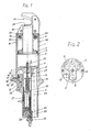
- Fig. 1 zeigt einen Axialschnitt der Rebenschere gemäß Linie I-I der Fig. 2.
- Fig. 2 ist eine Draufsicht auf den Boden der Expansionskammer bei eingesetzter Ventilplatte.
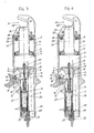
- Die Fig. 3 bis 8 sind der Fig. 1 analoge Schnittdarstellungen, geben jedoch aufeinanderfolgend die Abfolge der Bewegungen der einzelnen Teile bei Betätigung der erfindungsgemäßen Vorrichtung wieder.
- 1 shows an axial section of the pruning shears according to line II of FIG. 2.
- Fig. 2 is a top view of the bottom of the expansion chamber with the valve plate in place.
- 3 to 8 are sectional views analogous to FIG. 1, but in succession represent the sequence of the movements of the individual parts when the device according to the invention is actuated.
Mit 1 ist ein Zylinder bezeichnet, in welchem ein Kolben 2 dichtend geführt ist. Unterhalb des Kolbens ist ein Expansionsraum 3 vorgesehen, der am unteren Ende durch einen Boden 4 abgeschlossen ist. Der Kolben 2 ist dabei mittels einer Rückstellfeder 5 in seine zurückgezogene Lage belastet. In dieser Lage liegt der Kolben 2 an einem Anschlagring 6 an, und begrenzt damit den unteren Teil des Expansionsraumes 3. Dem Expansionsraum 3 ist eine Mischkammer 7 vorgeschaltet, welche über einen im Boden 4 vorgesehenen Durchlaß 8 mit dem Expansionsraum 3 verbunden ist. Im Boden 4 sind weiters noch zwei Auspuffdurchlässe 9 (siehe Fig. 2) vorgesehen, welche über Kanäle 10 seitlich nach außen führen. Der Durchlaß 8 sowie die Auspuffdurchlässe 9 sind durch eine Ventilplatte 11 abschließbar, welche vorliegend dreiflügelig ausgebildet ist. Es könnte selbstverständlich auch eine kreisförmige Ventilplatte vorgesehen sein. Die Grundrißform der Ventilplatte hängt lediglich von der Konfiguration und Anordnung der Durchlässe im Boden 4 ab. Die Ventilplatte 11 ist mit einem Stößel 12 fest verbunden, welcher am unteren Ende mit einem Schlagkopf 13 versehen ist. Dieser Schlagkopf, der mit dem Stößel 12 fest verbunden ist, ist vorliegend als Hülse ausgebildet, welche den Stößel über einen Teilbereich umgibt. Zwischen Stößel 12 und dem Hülsenteil des Schlagkopfes 13 ist eine Rückstellfeder 14 vorgesehen, welche den Stößel und damit die Ventilplatte im Sinne eines Schließens des Ventils belastet. An dem Hülsenteil des Schlagkopfes 13 ist ein nach außen wegragender Flansch 15 vorgesehen, welcher zum Eingriff eines Abzugshahnes 16 dient. Der Abbzugshahn 16 ist um einen Bolzen 17 schwenkbar gelagert, an welchem er über ein Langloch 18 angreift. Dieses Langloch 18 verläuft parallel zur Vorschubrichtung des Abzuges für das Ineingriffbringen, dessen Spitze 16′ hinter den Flansch 15 des Schlagkopfes 13 zu liegen kommt. Gemäß Fig. 1 ist der Abzugshahn 16 mittels eines Schiebers 19 gegen ein Eingreifen gesichert, wobei er mittels einer Feder 20 im Sinne eines Verschwenkens in Eingriffstellung belastet ist.1 with a cylinder is designated, in which a
Unterhalb des Schlagkopfes 13 ist eine piezoelektrische Zündeinrichtung 21 vorgesehen, welche mit einer im Expansionsraum 3 vorgesehenen Zündkerze verbunden 22 ist.Provided below the
Parallel zur piezoelektrischen Zündeinrichtung verläuft eine gleichfalls vom Schlagkopf 13 betätigbare Betätigungsstange 23, welche mit einem Gaszuströmsteuerventil 24 verbunden ist. Dieses Gaszuströmsteuerventil 24 ist als Stopfen ausgebildet, welcher für die Anlage an die Stirnfläche der Gasanschlußarmatur 25 zwecks Abschluß der Austrittsbohrung 26 ausgebildet ist.An
Die Ventilplatte 11 weist an ihrer Unterseite einen in den Durchlaß 8 reichenden Strömungskörper 27 auf, welcher zur Verwirbelung des austretenden Gas-Luft-Gemisches aus der Mischkammer 7 dient.The
Am Kolben 2 ist ein in Richtung zum oberen Ende des Zylinders 1 weisendes Schneidmesser 28 vorgesehen, welches durch den Deckel 29 des Zylinders hindurchgeht. Am äußeren Ende des Deckels 29 ist eine Messerführung 30 vorgesehen, welche eine in die Bewegungsbahn der Schneide 28′ des Messers 28 reichende Ausnehmung 31 aufweist, womit die Messerführung einen Haken bildet, in welchen die abzuschneidende Rebe eingesetzt wird. An der Unterseite des Deckels 29 ist ein aus elastischem Material bestehender Anschlag 32 für den Kolben vorgesehen.On the
Bei Inbetriebnahme der erfindungsgemäßen Einrichtung wird der Sicherungsschieber 19 in die in Fig. 3 wiedergegebene Stellung zurückgezogen, wodurch aufgrund der Feder 20 der Abzugshahn 16 in seine betriebsbereite Stellung verschwenkt wird, in welcher die Spitze 16′ unter den Flansch 15 des Schlagkopfes 13 weist. Die Feder 20 stützt sich dabei zusätzlich an dem Abstützbolzen 33, welcher dem Bolzen 17 benachbart ist, ab. Bei Betätigung des Abzugshahnes gleitet letzterer entlang des Langloches 18 am Bolzen 17 in Richtung zum Hülsenteil des Schlagkopfes 13, und zwar so lang, bis der Bolzen 17 am hinteren Ende des Langloches 18 anliegt. In dieser Stellung greift der Hahn 16 mit seiner Spitze 16′ unter den Flansch 15 ein (siehe diese Stellung in Fig. 4). Bei Weiterbewegen des Hahnes schwenkt letzterer um den Bolzen 17 und hebt den Flansch 15 und damit über den Schlagkopf 13 den Stößel 12 und die Ventilplatte 11 nach oben ab, wodurch der Durchlaß 8 zwischen Mischkammer 7 und Expansionsraum 3 frei wird. Dadurch kann das im Mischraum 7 befindliche Gas-Luft-Gemisch in den Expansionsraum 3 einströmen und letzteren füllen. Bei Weiterbewegen des Hahnes 16 kommt die Spitze 16′ aus dem Flansch 15 außer Eingriff, wodurch aufgrund der Rückstellfeder 14 der Schlagkopf 13 und damit die Ventilplatte 11 nach unten bewegt wird, wobei der Schlagkopf 13 auf die piezoelektrische Zündeinrichtung 21 aufschlägt, welche mittels der Zündkerze 22 das im Expansionsraum 3 befindliche Gemisch zündet (siehe Fig. 6). Gleichzeitig mit der Abwärtsbewegung des Schlagkopfes 13 wird auch die Betätigungsstange 23 nach unten geschoben, wodurch der Stopfen des Gaszuströmsteuerventils 24 die Gasaustrittsöffnung 26 der Gasanschlußarmatur 25 abschließt. Durch die Zündung des zündfähigen Gemisches im Expansionsraum 3 wird der Kolben schlagartig nach oben bewegt, wodurch das Messer 28 mit der Schneide 28′ über die Ausnehmung 31 der Messerführung hindurchbewegt wird, und dadurch die in der Ausnehmung 31 eingelegte Rebe abschneidet. Der Kolben ist dabei im Zylinder so weit nach oben bewegt, daß er an seiner Rückseite in der Kolbenwandung befindliche Ausgleichsöffnungen 34 freigibt, durch welche hindurch die Hauptmenge des expandierten Gases austreten kann. Danach wird dann der Kolben aufgrund der Rückstellfeder 5 wieder in seine Ausgangsstellung zurückbewegt, welche in Fig. 8 wiedergegeben ist. Wird nun der Abzugshahn 16 freigegeben, dann schwenkt er aufgrund der Feder 20 wieder in seine in Fig. 3 wiedergegebene Ausgangsstellung zurück.When starting up the device according to the invention, the
Die Steuerung der Gaszufuhr zur Mischkammer erfolgt dabei dadurch, daß durch das Anheben des Schlagkopfes 13 die Betätigungsstange 23 freigegeben wird, so daß aufgrund des Gasdruckes der Stopfen 24 des Gaszuströmsteuerventils nach oben bewegt wird, was ein öffnen der Gasaustrittsöffnung der Gasanschlußarmatur 25 bewirkt. Dadurch kann dann zündfähiges Gas in der entsprechenden Menge in die Mischkammer 7 einströmen, in welche gleichzeitig durch eine öffnung 35 Luft einströmen kann.The control of the gas supply to the mixing chamber takes place in that the actuating
Bei öffnen des Ventils 11 strömt dann das in der Mischkammer 7 befindliche Gas-Luft-Gemisch über den Durchlaß 8 wieder in den Expansionsraum 3 ein, wobei noch im Expansionsraum befindliche Verbrennungsgase durch die Auspuffdurchlässe 9 und die Kanäle 10 aus dem Expansionsraum 3 durch die einströmende Gas-Luft-Mischung verdrängt wird. Damit ist die Rebenschere für die nächste Betätigung betriebsbereit.When the
Wenn die Rebenschere nicht mehr gebraucht wird, dann wird durch Verschieben des Schiebers 19 in die in Fig. 1 wiedergegebene Stellung der Abzugshahn 16 gegen unbeabsichtigte Betätigung gesichert.When the pruning shears are no longer used, the
Wie schon angeführt, kann bei Ersatz des Messers 28 und der Messerführung 30 durch eine Schlageinrichtung die gleiche Antriebseinrichtung zum Betrieb eines Nageleinschlaggerätes oder eines Bolzensetzgerätes oder einer sonstigen analogen Einrichtung verwendet werden.As already mentioned, when the
Claims (13)
Applications Claiming Priority (2)
| Application Number | Priority Date | Filing Date | Title |
|---|---|---|---|
| AT1685/88 | 1988-06-29 | ||
| AT168588 | 1988-06-29 |
Publications (2)
| Publication Number | Publication Date |
|---|---|
| EP0349526A2 true EP0349526A2 (en) | 1990-01-03 |
| EP0349526A3 EP0349526A3 (en) | 1990-12-05 |
Family
ID=3518777
Family Applications (1)
| Application Number | Title | Priority Date | Filing Date |
|---|---|---|---|
| EP19890890177 Withdrawn EP0349526A3 (en) | 1988-06-29 | 1989-06-28 | Power-driven hand tool |
Country Status (1)
| Country | Link |
|---|---|
| EP (1) | EP0349526A3 (en) |
Cited By (2)
| Publication number | Priority date | Publication date | Assignee | Title |
|---|---|---|---|---|
| WO1995007800A1 (en) * | 1993-09-16 | 1995-03-23 | Husqvarna Ab | A pressure-medium operated tool |
| NL1037495C2 (en) * | 2009-11-24 | 2011-05-25 | Johannes Henricus Helena Maria Smits | DEVICE AND GESTURE FOR EDITING AN OBJECT, SUCH AS A TILE, CLINKER AND BRICK, AND COMPOSITION OF GESTEL AND EXPANSION UNIT. |
Family Cites Families (5)
| Publication number | Priority date | Publication date | Assignee | Title |
|---|---|---|---|---|
| NL244470A (en) * | 1958-10-18 | |||
| US4166374A (en) * | 1978-02-16 | 1979-09-04 | Babko Alexandr A | High-speed explosion hammer |
| US4405072A (en) * | 1980-05-28 | 1983-09-20 | Hilti Aktiengesellschaft | Setting device powered by an explosive gas mixture |
| AU572133B2 (en) * | 1983-04-18 | 1988-05-05 | Veldman, A.G.G. | Percussive tool with improved combustion chamber |
| CN1042217A (en) * | 1988-08-12 | 1990-05-16 | 阿尔方苏斯·格拉杜斯·古利穆斯·维尔曼 | Power tool drive system |
-
1989
- 1989-06-28 EP EP19890890177 patent/EP0349526A3/en not_active Withdrawn
Cited By (2)
| Publication number | Priority date | Publication date | Assignee | Title |
|---|---|---|---|---|
| WO1995007800A1 (en) * | 1993-09-16 | 1995-03-23 | Husqvarna Ab | A pressure-medium operated tool |
| NL1037495C2 (en) * | 2009-11-24 | 2011-05-25 | Johannes Henricus Helena Maria Smits | DEVICE AND GESTURE FOR EDITING AN OBJECT, SUCH AS A TILE, CLINKER AND BRICK, AND COMPOSITION OF GESTEL AND EXPANSION UNIT. |
Also Published As
| Publication number | Publication date |
|---|---|
| EP0349526A3 (en) | 1990-12-05 |
Similar Documents
| Publication | Publication Date | Title |
|---|---|---|
| DE69512018T2 (en) | Combustion gas powered fastener driving tool with combustion gas actuated fastener advance mechanism | |
| DE1144205B (en) | Internal combustion impact device, in particular internal combustion hammer | |
| DE1868901U (en) | SPRINGLESS PRESSURE VALVE. | |
| EP0223740A2 (en) | Powder-actuated nail-setting tool | |
| DE1291699B (en) | Bolt driving tool | |
| DE10308359B4 (en) | Internal combustion-powered setting tool | |
| EP0467834B1 (en) | Powder-actuated fastener driving tool | |
| DE2604287A1 (en) | DEVICE FOR DRIVING FASTENING MEANS | |
| DE19821756C2 (en) | Drive device for a shut-off device in a pipeline | |
| EP3083150A1 (en) | Work tool | |
| DE10259567A1 (en) | Combustion-powered setting tool | |
| EP1922568B1 (en) | Method and device for generating compression waves | |
| DE19805442A1 (en) | Nail setting tool for concrete, steel, etc. | |
| EP0349526A2 (en) | Power-driven hand tool | |
| DE4010517B4 (en) | Gas powered implement | |
| DE2536881A1 (en) | PENCIL-SHAPED GAS LIGHTER | |
| DE102005000032A1 (en) | Internal combustion setting device | |
| DE2736461C2 (en) | ||
| DE1284368B (en) | Internal combustion impact tool | |
| DE10346985A1 (en) | Hand-operated setting tool | |
| DE19962698C2 (en) | Combustion powered tool with combustion chamber pressure control | |
| DE19853554C1 (en) | Gas-operated bolt setting apparatus has pistol-type housing containing barrel in which piston is movable in combustion chamber filled with gas - air mixture and opposite to which bolt guide is axially displaceable in bolt guide socket | |
| DE1628013B2 (en) | BOLT FASTENING DEVICE FOR A SLEEVE-LESS DRIVING CHARGE, DESIGNED AS A SOLID MOLDED BODY | |
| DE1709401C3 (en) | Starting device for a diesel pile hammer | |
| DE19853556C1 (en) | Gas-actuated stud setter has pressure casing between stud delivery casing, stud channel axially movable with control rod when delivery casing pushed against spring force to free actuator |
Legal Events
| Date | Code | Title | Description |
|---|---|---|---|
| PUAI | Public reference made under article 153(3) epc to a published international application that has entered the european phase |
Free format text: ORIGINAL CODE: 0009012 |
|
| AK | Designated contracting states |
Kind code of ref document: A2 Designated state(s): AT BE CH DE ES FR GB GR IT LI LU NL SE |
|
| PUAL | Search report despatched |
Free format text: ORIGINAL CODE: 0009013 |
|
| AK | Designated contracting states |
Kind code of ref document: A3 Designated state(s): AT BE CH DE ES FR GB GR IT LI LU NL SE |
|
| STAA | Information on the status of an ep patent application or granted ep patent |
Free format text: STATUS: THE APPLICATION IS DEEMED TO BE WITHDRAWN |
|
| 18D | Application deemed to be withdrawn |
Effective date: 19910606 |