EP0349250A2 - Soupape de réglage du type ET - Google Patents
Soupape de réglage du type ET Download PDFInfo
- Publication number
- EP0349250A2 EP0349250A2 EP19890306487 EP89306487A EP0349250A2 EP 0349250 A2 EP0349250 A2 EP 0349250A2 EP 19890306487 EP19890306487 EP 19890306487 EP 89306487 A EP89306487 A EP 89306487A EP 0349250 A2 EP0349250 A2 EP 0349250A2
- Authority
- EP
- European Patent Office
- Prior art keywords
- valve
- return
- piston
- return valve
- sensitive means
- Prior art date
- Legal status (The legal status is an assumption and is not a legal conclusion. Google has not performed a legal analysis and makes no representation as to the accuracy of the status listed.)
- Granted
Links
- 239000012530 fluid Substances 0.000 claims description 6
- 238000011144 upstream manufacturing Methods 0.000 claims description 3
- 230000009977 dual effect Effects 0.000 description 2
- 238000002347 injection Methods 0.000 description 2
- 239000007924 injection Substances 0.000 description 2
- 239000002991 molded plastic Substances 0.000 description 2
- 230000035945 sensitivity Effects 0.000 description 2
- 238000004891 communication Methods 0.000 description 1
- 230000000881 depressing effect Effects 0.000 description 1
- 238000010586 diagram Methods 0.000 description 1
- 238000003754 machining Methods 0.000 description 1
- 238000004519 manufacturing process Methods 0.000 description 1
- 229910052751 metal Inorganic materials 0.000 description 1
- 239000002184 metal Substances 0.000 description 1
- 150000002739 metals Chemical class 0.000 description 1
- 230000000979 retarding effect Effects 0.000 description 1
Images
Classifications
-
- F—MECHANICAL ENGINEERING; LIGHTING; HEATING; WEAPONS; BLASTING
- F16—ENGINEERING ELEMENTS AND UNITS; GENERAL MEASURES FOR PRODUCING AND MAINTAINING EFFECTIVE FUNCTIONING OF MACHINES OR INSTALLATIONS; THERMAL INSULATION IN GENERAL
- F16K—VALVES; TAPS; COCKS; ACTUATING-FLOATS; DEVICES FOR VENTING OR AERATING
- F16K11/00—Multiple-way valves, e.g. mixing valves; Pipe fittings incorporating such valves
- F16K11/02—Multiple-way valves, e.g. mixing valves; Pipe fittings incorporating such valves with all movable sealing faces moving as one unit
- F16K11/04—Multiple-way valves, e.g. mixing valves; Pipe fittings incorporating such valves with all movable sealing faces moving as one unit comprising only lift valves
- F16K11/048—Multiple-way valves, e.g. mixing valves; Pipe fittings incorporating such valves with all movable sealing faces moving as one unit comprising only lift valves with valve seats positioned between movable valve members
Definitions
- This invention relates to an AND-type control valve particularly though not exclusively, for use in controlling operation of a trailer brake valve in a master cylinder-type vehicle braking system.
- Many constructional and agricultural vehicles employ separate hydraulic braking circuits for the left hand and right hand sides of the vehicle for the purpose of steering or assisting in the steering of the vehicle. They may be high pressure circuits supplied by a pump or accumulator, or simple master cylinder/slave cylinder circuits as per most agricultural vehicles. In this case it is usual to have two independent master cylinders, each operated by its own brake pedal, and for the purpose of braking the vehicle, the two pedals are coupled together, and for the purpose of steering the two pedals are uncoupled and operated separately.
- the trailer brakes When the vehicle is fitted with a trailer brake valve, operated by the vehicle's own brakes, it is desirable for the trailer brakes to operate only when the vehicle brakes are used for braking and not for steering. As such, it is necessary for the trailer brake valve to operate only when both right hand and left hand brake circuits are pressurised.
- Such a valve using control logic terms, can be known as a "AND" type trailer brake valve.
- AND type logic valves are well known, one such case being two opposing non-return valves with a push rod interspaced between them of sufficient length so that when one non-return valve is seated, the other is held open by the push rod.
- a similar type can be constructed without the push rod, providing the two opposing poppet elements are either extended or their seats are placed so close together so as to prevent both from closing at the same time.
- the poppet element is made to close by the action of fluid through the circumferential area between the poppet and the seat and to ensure that flow is not too large this area must be kept small.
- the flow required to close this type of logic valve represents a leakage flow and increased pedal travel and must therefore be kept to a minimum. This then means controlling the circumferential area to unacceptably tight tolerances.
- One object of the present invention is to avoid these problems.
- an AND-type control valve comprising a control output port, two input flowpaths communicating with the outlet port each via a non-return valve, the valves being arranged such that both cannot be open at the same time and each having associated therewith flow sensitive means to assist closure of the non-return valve.
- the flow sensitive means is preferably a piston running in a bore and incorporating an orifice whereby a small flow of fluid passing across or along the orifice gives rise to a pressure drop imparting motion to the piston which thus acts to close the non-return valve.
- the non-return valve is a poppet valve element integral with the piston which runs in a bore concentric with the valve seat.
- the pistons are each downstream of their associated poppet valve the pistons are opposed and abut so as to ensure that when one non-return valve is closed, the other is held open.
- pistons and their respective orifices could be positioned upstream of the poppet seats, whereby the pressure drop across the piston causes a pushing force to close the poppet, instead of a pulling force.
- the piston and poppet could then be separate components if it was found advantageous to a particular manufacturing method.
- the poppet seat and piston bore need not be concentric, and the poppet could be replaced by a ball.
- the invention includes a tractor-trailer braking system comprising separate hydraulic circuits controlling respectively brakes for the left hand and right hand sides of the vehicle, a trailer brake valve responsive to a control signal from the outlet port of an AND-type control valve according to this invention, one of said input flowpaths thereof being connected one to the left hand hydraulic circuit and the other being connected to the right hand hydraulic circuit.
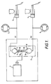
- the circuit of Figure 1 includes a trailer brake valve 1 and an "AND"-type control valve or head 2 with two inputs Y1 and Y2. These are supplied with fluid from hydraulic master cylinders 3 and 4 respectively which are also connected to the vehicle's brakes, in this case an agricultural tractor, 5 and 6.
- the "AND" head has two opposing non-return valves 7, 8 with integral pistons 9, 10 of sufficient length to prevent both non-return valves from closing at the same time, also each piston incorporates an orifice 11 and 12. Between the two non-return valves is a passage 16 leading to trailer brake valve 1. When pressurised trailer brake valve 1 operates to produce a proportionally higher pressure at the trailer brakes.
- the flow throughout orifices 11 and 12 will create a pressure drop across the pistons 9 and 10 to further open non-return valve 8 and close non-return valve 7, preventing further flow leaking from master cylinder 3 to master cylinder 4. Since the flow to close non-return valve 7 is determined by the size of orifice 11, the circumferential area formed by the poppet opening can be relatively large, removing the need for tight tolerances on the poppet lift. Also, the flow can be made to be extremely small.
- both tractor brakes 5 and 6 will be applied. Since it is customary for most dual brake circuits to have some means of equalising the pressure (not shown), in the two circuits when both lines are pressurised, then the tractor will be retarded in a straight line, without steering to the right or left. Also, pressure will be applied to both ports Y1 and Y2. Since both non-return valves 7, 8 cannot be closed at the same time, pressure will be transmitted through the open non-return valve to passage 16 and the trailer brake valve 1 will operate. Therefore the trailer brake valve only operates when both brakes lines are pressurised, i.e. when the tractor brakes are coupled together and operated for the purpose of retarding the vehicle and the trailer brake valve does not operate when only one tractor brake is applied, for the purpose of steering the vehicle.
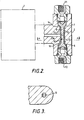
- the "AND" head contains a through bore 13, with two opposing, concentric, cone seats 14 and 15. Slidably engaged in bore 13 are two poppets 7, 8 with integral pistons 9, 10 containing two diametrically opposite, axial grooves, which when engaged in bore 13, form axial orifices 11, 12.
- the combined lengths of pistons 9, 10 is such that only one poppet 7,8 can be closed against its corresponding seat 14, 15 at the same time.
- the end of each piston 9,10 is reduced to allow flow communication with cross hole 16, which connects with trailer brake valve 1.
- the "AND" head functions as previously described with each poppet, in the steering mode, being closed or made to close by the action of fluid passing through its corresponding orifice 11, 12.
- the orifices could be sharp edges and positioned either radially or axially, but a long, thin orifice as shown, increases the flow sensitivity.
- the poppets could be made of various metals, with or without an elastomeric seal, but a preferred design utilises an injection moulded plastic, with sufficient resilience, tensile strength, temperature and creep resistance etc., to give a 100% leak free seal, at the extremes of temperature and pressure imposed by a tractor braking system.
- Injection moulded plastic also has the advantages of light weight and low friction, increasing still further the flow sensitivity of the design and is economical to produce, since no machining is required.
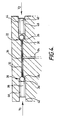
- the opposed non-return valves 20 and 22 are formed by balls 24 and 26 cooperating respectively with conical seats 28 and 30.
- the two non-return valves cannot be open at the same time.
- Pistons 38 and 40 are disposed respectively in the bores 42 and 44 upstream of the associated non-return valve in the input flowpath from the input port Y1, Y2 so that the resistance to flow along the orifices 46 and 48 creates a pressure drop causing movement of the piston to push the ball 24, 26 into its seat.
Landscapes
- Engineering & Computer Science (AREA)
- General Engineering & Computer Science (AREA)
- Mechanical Engineering (AREA)
- Valves And Accessory Devices For Braking Systems (AREA)
- Transmission Of Braking Force In Braking Systems (AREA)
Applications Claiming Priority (2)
| Application Number | Priority Date | Filing Date | Title |
|---|---|---|---|
| GB888815703A GB8815703D0 (en) | 1988-07-01 | 1988-07-01 | Type control valve |
| GB8815703 | 1988-07-01 |
Publications (3)
| Publication Number | Publication Date |
|---|---|
| EP0349250A2 true EP0349250A2 (fr) | 1990-01-03 |
| EP0349250A3 EP0349250A3 (en) | 1990-10-17 |
| EP0349250B1 EP0349250B1 (fr) | 1994-05-04 |
Family
ID=10639715
Family Applications (1)
| Application Number | Title | Priority Date | Filing Date |
|---|---|---|---|
| EP19890306487 Expired - Lifetime EP0349250B1 (fr) | 1988-07-01 | 1989-06-27 | Soupape de réglage du type ET |
Country Status (3)
| Country | Link |
|---|---|
| EP (1) | EP0349250B1 (fr) |
| DE (1) | DE68915066T2 (fr) |
| GB (1) | GB8815703D0 (fr) |
Family Cites Families (5)
| Publication number | Priority date | Publication date | Assignee | Title |
|---|---|---|---|---|
| DD48274A (fr) * | ||||
| US1409116A (en) * | 1916-08-08 | 1922-03-07 | Fire Gun Mfg Company Inc | Valve |
| US2395941A (en) * | 1943-12-24 | 1946-03-05 | Pesco Products Co | Double check unloading valve |
| US2847182A (en) * | 1952-01-31 | 1958-08-12 | Hydra Power Corp | Valve structure |
| AU2154083A (en) * | 1982-12-06 | 1984-06-14 | Deere & Company | Shuttle check valve |
-
1988
- 1988-07-01 GB GB888815703A patent/GB8815703D0/en active Pending
-
1989
- 1989-06-27 EP EP19890306487 patent/EP0349250B1/fr not_active Expired - Lifetime
- 1989-06-27 DE DE1989615066 patent/DE68915066T2/de not_active Expired - Fee Related
Also Published As
| Publication number | Publication date |
|---|---|
| EP0349250A3 (en) | 1990-10-17 |
| GB8815703D0 (en) | 1988-08-10 |
| DE68915066T2 (de) | 1994-08-18 |
| DE68915066D1 (de) | 1994-06-09 |
| EP0349250B1 (fr) | 1994-05-04 |
Similar Documents
| Publication | Publication Date | Title |
|---|---|---|
| KR20010015827A (ko) | 자동차 전자-유압제동설치부용 마스터실린더 | |
| US5176433A (en) | Vacuum servo unit for use in traction control | |
| US4586591A (en) | Pressure-fluid-operable vehicle brake system | |
| US6729132B2 (en) | Remotely and directly pedal operated hydraulic compact booster for bi-directional braking | |
| SE451697B (sv) | Hydrauliskt bromssystem med slirningsreglering | |
| JPS62168752A (ja) | スリツプ制御液圧サ−ボブレ−キシステム | |
| US6053582A (en) | Integrated ABS/TC/VSC braking system with separate boost valve | |
| US5882090A (en) | Traction control system having pilot operated valves | |
| US5190356A (en) | AND-type control valve for a tractor-trailer braking system | |
| EP0218823B1 (fr) | Soupape antipatinage pour système de freinage assisté | |
| US6217128B1 (en) | Dual brake valve for a steering assist system | |
| US4196592A (en) | Hydraulic brake booster | |
| US4516400A (en) | Master cylinder assembly for a vehicle braking system | |
| US5179835A (en) | Brake valve for use in load sensing hydraulic system | |
| EP0349250B1 (fr) | Soupape de réglage du type ET | |
| US5960629A (en) | Control apparatus for a brake booster | |
| US4408805A (en) | Control valve assemblies for hydraulic braking systems | |
| US4336869A (en) | Steering clutch and brake control for track-type vehicles | |
| US4852351A (en) | Dual-circuit master cylinder with solenoid opened reservoir valve | |
| US6206487B1 (en) | Brake pressure control device | |
| US5937649A (en) | Brake master cylinder with return connection | |
| GB2188386A (en) | Hydraulic brake system | |
| US20060071547A1 (en) | Valve assembly for anti-skid aircraft brakes | |
| US5470137A (en) | Copy valve for an anti-lock brake system | |
| US5174635A (en) | Hydraulic braking pressure control system for rear wheel brake |
Legal Events
| Date | Code | Title | Description |
|---|---|---|---|
| PUAI | Public reference made under article 153(3) epc to a published international application that has entered the european phase |
Free format text: ORIGINAL CODE: 0009012 |
|
| AK | Designated contracting states |
Kind code of ref document: A2 Designated state(s): DE FR GB IT SE |
|
| PUAL | Search report despatched |
Free format text: ORIGINAL CODE: 0009013 |
|
| AK | Designated contracting states |
Kind code of ref document: A3 Designated state(s): DE FR GB IT SE |
|
| 17P | Request for examination filed |
Effective date: 19901221 |
|
| RAP3 | Party data changed (applicant data changed or rights of an application transferred) |
Owner name: WABCO AUTOMOTIVE U.K. LIMITED |
|
| 17Q | First examination report despatched |
Effective date: 19920825 |
|
| GRAA | (expected) grant |
Free format text: ORIGINAL CODE: 0009210 |
|
| AK | Designated contracting states |
Kind code of ref document: B1 Designated state(s): DE FR GB IT SE |
|
| REF | Corresponds to: |
Ref document number: 68915066 Country of ref document: DE Date of ref document: 19940609 |
|
| ITF | It: translation for a ep patent filed | ||
| ET | Fr: translation filed | ||
| EAL | Se: european patent in force in sweden |
Ref document number: 89306487.3 |
|
| PLBE | No opposition filed within time limit |
Free format text: ORIGINAL CODE: 0009261 |
|
| STAA | Information on the status of an ep patent application or granted ep patent |
Free format text: STATUS: NO OPPOSITION FILED WITHIN TIME LIMIT |
|
| 26N | No opposition filed | ||
| REG | Reference to a national code |
Ref country code: GB Ref legal event code: IF02 |
|
| PGFP | Annual fee paid to national office [announced via postgrant information from national office to epo] |
Ref country code: GB Payment date: 20040608 Year of fee payment: 16 |
|
| PGFP | Annual fee paid to national office [announced via postgrant information from national office to epo] |
Ref country code: SE Payment date: 20040611 Year of fee payment: 16 |
|
| PGFP | Annual fee paid to national office [announced via postgrant information from national office to epo] |
Ref country code: FR Payment date: 20040630 Year of fee payment: 16 |
|
| PGFP | Annual fee paid to national office [announced via postgrant information from national office to epo] |
Ref country code: DE Payment date: 20040721 Year of fee payment: 16 |
|
| PG25 | Lapsed in a contracting state [announced via postgrant information from national office to epo] |
Ref country code: IT Free format text: LAPSE BECAUSE OF NON-PAYMENT OF DUE FEES Effective date: 20050627 Ref country code: GB Free format text: LAPSE BECAUSE OF NON-PAYMENT OF DUE FEES Effective date: 20050627 |
|
| PG25 | Lapsed in a contracting state [announced via postgrant information from national office to epo] |
Ref country code: SE Free format text: LAPSE BECAUSE OF NON-PAYMENT OF DUE FEES Effective date: 20050628 |
|
| PG25 | Lapsed in a contracting state [announced via postgrant information from national office to epo] |
Ref country code: DE Free format text: LAPSE BECAUSE OF NON-PAYMENT OF DUE FEES Effective date: 20060103 |
|
| EUG | Se: european patent has lapsed | ||
| PG25 | Lapsed in a contracting state [announced via postgrant information from national office to epo] |
Ref country code: FR Free format text: LAPSE BECAUSE OF NON-PAYMENT OF DUE FEES Effective date: 20060228 |
|
| GBPC | Gb: european patent ceased through non-payment of renewal fee |
Effective date: 20050627 |
|
| REG | Reference to a national code |
Ref country code: FR Ref legal event code: ST Effective date: 20060228 |