US5176433A - Vacuum servo unit for use in traction control - Google Patents
Vacuum servo unit for use in traction control Download PDFInfo
- Publication number
- US5176433A US5176433A US07/587,931 US58793190A US5176433A US 5176433 A US5176433 A US 5176433A US 58793190 A US58793190 A US 58793190A US 5176433 A US5176433 A US 5176433A
- Authority
- US
- United States
- Prior art keywords
- pressure chamber
- valve
- housing
- atmospheric pressure
- servo unit
- Prior art date
- Legal status (The legal status is an assumption and is not a legal conclusion. Google has not performed a legal analysis and makes no representation as to the accuracy of the status listed.)
- Expired - Fee Related
Links
Images


Classifications
-
- B—PERFORMING OPERATIONS; TRANSPORTING
- B60—VEHICLES IN GENERAL
- B60T—VEHICLE BRAKE CONTROL SYSTEMS OR PARTS THEREOF; BRAKE CONTROL SYSTEMS OR PARTS THEREOF, IN GENERAL; ARRANGEMENT OF BRAKING ELEMENTS ON VEHICLES IN GENERAL; PORTABLE DEVICES FOR PREVENTING UNWANTED MOVEMENT OF VEHICLES; VEHICLE MODIFICATIONS TO FACILITATE COOLING OF BRAKES
- B60T8/00—Arrangements for adjusting wheel-braking force to meet varying vehicular or ground-surface conditions, e.g. limiting or varying distribution of braking force
- B60T8/32—Arrangements for adjusting wheel-braking force to meet varying vehicular or ground-surface conditions, e.g. limiting or varying distribution of braking force responsive to a speed condition, e.g. acceleration or deceleration
- B60T8/34—Arrangements for adjusting wheel-braking force to meet varying vehicular or ground-surface conditions, e.g. limiting or varying distribution of braking force responsive to a speed condition, e.g. acceleration or deceleration having a fluid pressure regulator responsive to a speed condition
- B60T8/48—Arrangements for adjusting wheel-braking force to meet varying vehicular or ground-surface conditions, e.g. limiting or varying distribution of braking force responsive to a speed condition, e.g. acceleration or deceleration having a fluid pressure regulator responsive to a speed condition connecting the brake actuator to an alternative or additional source of fluid pressure, e.g. traction control systems
- B60T8/4809—Traction control, stability control, using both the wheel brakes and other automatic braking systems
- B60T8/4827—Traction control, stability control, using both the wheel brakes and other automatic braking systems in hydraulic brake systems
- B60T8/4845—Traction control, stability control, using both the wheel brakes and other automatic braking systems in hydraulic brake systems using a booster or a master cylinder for traction control
- B60T8/4854—Traction control, stability control, using both the wheel brakes and other automatic braking systems in hydraulic brake systems using a booster or a master cylinder for traction control pneumatic boosters
-
- B—PERFORMING OPERATIONS; TRANSPORTING
- B60—VEHICLES IN GENERAL
- B60T—VEHICLE BRAKE CONTROL SYSTEMS OR PARTS THEREOF; BRAKE CONTROL SYSTEMS OR PARTS THEREOF, IN GENERAL; ARRANGEMENT OF BRAKING ELEMENTS ON VEHICLES IN GENERAL; PORTABLE DEVICES FOR PREVENTING UNWANTED MOVEMENT OF VEHICLES; VEHICLE MODIFICATIONS TO FACILITATE COOLING OF BRAKES
- B60T13/00—Transmitting braking action from initiating means to ultimate brake actuator with power assistance or drive; Brake systems incorporating such transmitting means, e.g. air-pressure brake systems
- B60T13/10—Transmitting braking action from initiating means to ultimate brake actuator with power assistance or drive; Brake systems incorporating such transmitting means, e.g. air-pressure brake systems with fluid assistance, drive, or release
- B60T13/24—Transmitting braking action from initiating means to ultimate brake actuator with power assistance or drive; Brake systems incorporating such transmitting means, e.g. air-pressure brake systems with fluid assistance, drive, or release the fluid being gaseous
- B60T13/46—Vacuum systems
- B60T13/52—Vacuum systems indirect, i.e. vacuum booster units
- B60T13/57—Vacuum systems indirect, i.e. vacuum booster units characterised by constructional features of control valves
-
- B—PERFORMING OPERATIONS; TRANSPORTING
- B60—VEHICLES IN GENERAL
- B60T—VEHICLE BRAKE CONTROL SYSTEMS OR PARTS THEREOF; BRAKE CONTROL SYSTEMS OR PARTS THEREOF, IN GENERAL; ARRANGEMENT OF BRAKING ELEMENTS ON VEHICLES IN GENERAL; PORTABLE DEVICES FOR PREVENTING UNWANTED MOVEMENT OF VEHICLES; VEHICLE MODIFICATIONS TO FACILITATE COOLING OF BRAKES
- B60T13/00—Transmitting braking action from initiating means to ultimate brake actuator with power assistance or drive; Brake systems incorporating such transmitting means, e.g. air-pressure brake systems
- B60T13/10—Transmitting braking action from initiating means to ultimate brake actuator with power assistance or drive; Brake systems incorporating such transmitting means, e.g. air-pressure brake systems with fluid assistance, drive, or release
- B60T13/66—Electrical control in fluid-pressure brake systems
- B60T13/72—Electrical control in fluid-pressure brake systems in vacuum systems or vacuum booster units
Definitions
- the present invention relates to a vacuum servo unit for use in a vehicle braking system.
- the present invention relates to a servo unit of the type comprising a housing, the interior of which housing is divided into two chambers by a flexible diaphragm, one chamber being connectible to the exhaust manifold of an engine and thus then being subjected to a vacuum pressure, while the other chamber is connectible via a valve assembly to atmospheric pressure, so that the pressure difference across the diaphragm aids axial movement of a brake actuator rod assembly which extends through the housing and is connected to the diaphragm and to a master cylinder and brake pedal.
- the present invention relates to a servo unit of the above-described type wherein a key arrangement limits the movement of a control piston of the valve assembly relative to a power piston which is connected to the diaphragm.
- a key arrangement limits the movement of a control piston of the valve assembly relative to a power piston which is connected to the diaphragm.
- a key arrangement is disclosed in Spanish Patent Application No. 551,919, filed by the assignee of the present application.
- a key is located in a recess in the control piston and abuts against the servo housing to thereby set a predetermined retracted position for said control piston, in which set piston a valve connecting with the source of vacuum pressure is closed.
- the present invention thus aims to modify the above balanced type of servo unit for advantageous immediate response use in a traction control system.
- a servo unit for use in a vehicle braking system, the servo unit comprising a housing within which a flexible diaphragm separates a vacuum pressure chamber from an atmospheric pressure chamber, an actuator rod assembly extending through the housing and including a valve assembly having a valve control piston which has a laterally extending key, said valve control piston together with a power piston connected to the flexible diaphragm, being engageable with a valve closure member, said valve control piston together with the valve closure member controlling the communication of the atmospheric pressure chamber with the atmosphere, and said power piston together with the valve closure member controlling the connection between the atmospheric pressure chamber and said vacuum pressure chamber, said laterally extending key being engageable with a fixed stop in the housing to limit the movement of the valve control piston and cause a balance to be set up in the valve assembly between the pressure in the vacuum pressure chamber and the pressure in the atmospheric pressure chamber when the actuator rod assembly is moved in a direction which would release the braking system, a solenoid valve being controllable to either connect a flexible passage
- bypass thus enables the atmospheric pressure chamber to be immediately connected to atmospheric pressure as and when traction control is required, whilst allowing for the advantageous immediate response of the balanced valve facility produced by the lateral key design of the valve control piston.
- the bypass is a pipe which extends externally of the housing.
- the bypass may pass, at least partially, through the wall of the housing, or through the diaphragm within the flexible passage member.
- an axially flexible tube extends between the diaphragm and a wall of the housing, across the vacuum pressure chamber, the tube connecting the solenoid valve with the atmospheric chamber of the housing.
- at least one tie bar extends through the axially flexible tube which is connected across the vacuum pressure chamber between the diaphragm and the wall of the housing.
- One end region of this flexible tube opens through the diaphragm into the atmospheric pressure chamber, whilst the other end region connects with the solenoid valve via a further pipe.
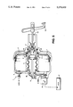
- FIG. 1 is a cross-sectional view through one embodiment of the present invention
- FIG. 2 is a cross-sectional view through another embodiment of the present invention.
- FIG. 3 is a cross-sectional view through a further embodiment of the present invention.
- FIG. 4 is a cross-sectional view through a still further embodiment of the present invention.
- FIG. 5 is a cross-sectional view through a still further embodiment of the present invention.
- FIG. 6 is an enlarged detailed view illustrating the valve assembly of the embodiments of FIGS. 1 to 5.
- the servo units illustrated in FIGS. 1 to 5 of the accompanying drawings comprise a housing 1 which is divided internally into a vacuum pressure chamber 3 and an atmospheric pressure chamber 5 by a flexible diaphragm 7.
- the diaphragm 7 includes a power piston 9 which is connected in an actuator rod assembly 11.
- the actuator rod assembly 11 extends through the housing 1 and projects from either side, one end region 13 being connected to a master cylinder (not shown) and the other end region being connected to a brake pedal 15.
- a valve assembly 17 controls the flow of air to the atmospheric pressure chamber 5, air normally entering the unit via inlet 19.
- This valve assembly 17 incorporates a key arrangement 21 schematically illustrated in FIGS. 1 to 5 and best seen in FIG. 6 of the accompanying drawings.
- the valve assembly 17 is constituted by an annular valve closure member 51 which is spring biassed by a spring 53 against an annular edge 55 of the power piston 9, said power piston 9 being connected to the diaphragm 7. Whilst one end of the spring 53 engages the valve closure member 51, the other end of the spring 53 engages on a shoulder of a brake actuator rod 57 forming part of the actuator rod assembly 11, said actuator rod 57 being connected to the brake pedal 15.
- the actuator rod 57 extends through the annular valve closure member 51 and is also coupled with the valve control piston 23, the key 21 extending laterally of the control piston 23 through a slot 59 in the wall of the power piston, and engaging against a stop or shoulder 61 in the wall of the housing 1 when the servo is in the rest position, the shoulder and key determining the rest position of the control piston 23.
- the key 21 limits the available movement of the control piston 23 relative to the servo housing 1 and results in a balanced condition when the brakes are released and the servo unit is at rest. In this balanced condition an annular edge 63 of the control piston 23 engages the valve closure member 51 and forms a closed atmospheric pressure valve preventing atmospheric pressure from entering the atmospheric pressure chamber 5 through the annular closure member 51 and the slot 59.
- said annular edge 55 of the power piston 9 engages the closure member 51 radially outside the annular edge 63 to form a closed vacuum pressure valve, a passage 65 leading through the power piston 9 from the vacuum pressure chamber 3 to a location radially outside the annular edge 55.
- a solenoid valve 25 is provided in the wall of the housing 1, the solenoid valve 25 being controlled by an electronic control unit 27 which monitors speed and torque at the vehicle wheels.
- the solenoid valve 25 opens a passage 26 between the vacuum pressure chamber 3 and an axially flexible passage member 29 which extends from the power piston 9 to the wall of the housing, across the vacuum pressure chamber 3 and around the actuator rod assembly 11.
- the solenoid valve 25 closes the passage 26 to the vacuum pressure chamber 3, and opens the passage 26 to the atmosphere.
- atmospheric pressure is fed to the axially flexible passage member 29.
- a bypass 35 incorporating a one-way valve 33, extends from the solenoid valve 25 to the atmospheric pressure chamber 5 so that when traction control is required, the bypass 31 is opened to allow atmospheric pressure to be introduced into the atmospheric pressure chamber 5.
- the one-way valve 33 retains the pressure in the atmospheric pressure chamber 5 during normal braking when valve assembly 17 opens to allow air under atmospheric pressure to enter the atmospheric pressure chamber 5 via inlet 19.
- the bypass 31 is a pipe 35 which extends externally of the housing.
- the bypass 31 has a section 37 which extends through the wall of the housing 1, this section 37 being connected by a pipe 39 in the vacuum pressure chamber 3 to the one-way valve 33.
- the bypass 31 is formed by an axially flexible tube 41 which extends across the vacuum pressure chamber 3 from the diaphragm 7 to the wall of the housing 1 adjacent to the solenoid valve 25, the tube 41 flexing as the diaphragm 7 moves.
- the tube 41 connects, through the diaphragm 7, with the atmospheric pressure chamber 5.
- FIG. 4 A modified form of the embodiment of FIG. 3 is shown in FIG. 4, the housing 1 of the embodiment of FIG. 4 being of a lightweight design and requiring axial tie bars 43 to strengthen its construction.
- One of these tie bars 43 extends through an axially flexible tube 41, the tube 41 connecting, through the diaphragm 7, with the atmospheric pressure chamber 5, and by a further pipe 45 with the one-way valve 33 and solenoid valve 25.
- FIG. 5 of the accompanying drawings A still further embodiment of the present invention is shown in FIG. 5 of the accompanying drawings, the bypass 35 being provided by passages 47 which extend through the power piston 9 connecting the flexible passage member 29 to the atmospheric pressure chamber 5.
- the solenoid valve 25 opens the flexible passage member 29 to the atmosphere so that atmospheric pressure immediately passes to the atmospheric pressure chamber 5 to actuate the servo unit and apply the brakes.
- the flexible passage member 29 is connected to the vacuum pressure chamber 3 via the solenoid valve 25, flap valves 49, i.e. the said one-way valve, being closed to prevent the chambers 3,5 from interconnecting.
- the present invention thus provides a servo unit with immediate response for normal braking, and with a traction control facility.
Abstract
Description
Claims (7)
Applications Claiming Priority (2)
| Application Number | Priority Date | Filing Date | Title |
|---|---|---|---|
| GB898920588A GB8920588D0 (en) | 1989-09-12 | 1989-09-12 | Improvements relating to a vacuum servo unit for use in traction control |
| GB8920588 | 1989-09-12 |
Publications (1)
| Publication Number | Publication Date |
|---|---|
| US5176433A true US5176433A (en) | 1993-01-05 |
Family
ID=10662929
Family Applications (1)
| Application Number | Title | Priority Date | Filing Date |
|---|---|---|---|
| US07/587,931 Expired - Fee Related US5176433A (en) | 1989-09-12 | 1990-09-12 | Vacuum servo unit for use in traction control |
Country Status (9)
| Country | Link |
|---|---|
| US (1) | US5176433A (en) |
| EP (1) | EP0417945B1 (en) |
| JP (1) | JPH03143763A (en) |
| KR (1) | KR970001505B1 (en) |
| BR (1) | BR9004530A (en) |
| CZ (1) | CZ279831B6 (en) |
| DE (1) | DE69006300T2 (en) |
| ES (1) | ES2050962T3 (en) |
| GB (1) | GB8920588D0 (en) |
Cited By (12)
| Publication number | Priority date | Publication date | Assignee | Title |
|---|---|---|---|---|
| US5265945A (en) * | 1992-02-17 | 1993-11-30 | Mazda Motor Corporation And Naldec Corporation | Slip control system for vehicle |
| US5275265A (en) * | 1991-09-30 | 1994-01-04 | Bendix Europe Services Techniques | Brake-booster with modulated reaction |
| US5338107A (en) * | 1993-11-03 | 1994-08-16 | Alliedsignal Inc. | Control valve actuator |
| US5357846A (en) * | 1993-11-24 | 1994-10-25 | Alliedsignal Inc. | Tandem brake booster |
| WO1994027847A1 (en) * | 1993-05-28 | 1994-12-08 | Allied Signal, Inc. | Control valve actuator for vacuum brake force booster |
| US5388897A (en) * | 1993-08-23 | 1995-02-14 | Alliedsignal Inc. | Vacuum brake booster with traction control |
| US5709437A (en) * | 1994-05-26 | 1998-01-20 | Lucas Industries, Public Limited Company | Vehicle braking system |
| US6302497B1 (en) * | 1998-03-31 | 2001-10-16 | Tokico Ltd. | Vehicle brake control system |
| US6748846B2 (en) | 2002-02-15 | 2004-06-15 | Delphi Technologies, Inc. | Solenoid valve, vacuum booster diaphragm subassembly, and vacuum booster assembly |
| US6955044B1 (en) | 2004-08-19 | 2005-10-18 | Robert Bosch Gmbh | Reaction arrangement for brake booster |
| US20080173490A1 (en) * | 2007-01-20 | 2008-07-24 | Nissan Motor Co., Ltd. | Regenerative braking coordination device |
| US20100019566A1 (en) * | 2006-04-07 | 2010-01-28 | Calvo Jose Manuel | Brake booster device with damping element |
Families Citing this family (8)
| Publication number | Priority date | Publication date | Assignee | Title |
|---|---|---|---|---|
| GB8920588D0 (en) * | 1989-09-12 | 1989-10-25 | Lucas Ind Plc | Improvements relating to a vacuum servo unit for use in traction control |
| DE4227286C2 (en) * | 1992-08-18 | 1996-08-29 | Lucas Ind Plc | Pneumatic brake booster, in particular for motor vehicles |
| DE4400688C2 (en) * | 1993-07-27 | 1998-10-15 | Lucas Ind Plc | Vehicle brake system with an electronically controlled amplifier |
| KR100329527B1 (en) * | 1993-07-27 | 2002-10-04 | 루카스 인더스트리즈 피엘씨 | Vehicle brake system with electronically controlled booster |
| KR100430548B1 (en) * | 2002-01-02 | 2004-05-10 | 엘지전자 주식회사 | System and method for controlling automatically an offset and an input gain of a projector |
| US8479608B2 (en) | 2007-02-03 | 2013-07-09 | Continental Teves Ag & Co. Ohg | Servo brake |
| DE102007044423A1 (en) | 2007-07-04 | 2009-01-15 | Continental Teves Ag & Co. Ohg | Brake booster |
| FR2945502A1 (en) * | 2009-05-18 | 2010-11-19 | Bosch Gmbh Robert | SERVOFREIN WITH ELECTROVALVE |
Citations (17)
| Publication number | Priority date | Publication date | Assignee | Title |
|---|---|---|---|---|
| US4398449A (en) * | 1980-01-21 | 1983-08-16 | Tokico Ltd. | Pneumatic servo booster |
| JPS59145652A (en) * | 1983-02-10 | 1984-08-21 | Mitsubishi Motors Corp | Antislip apparatus |
| EP0171585A2 (en) * | 1984-08-20 | 1986-02-19 | Allied Corporation | Brake booster providing vehicular hill holder |
| US4630706A (en) * | 1984-01-28 | 1986-12-23 | Tokico Ltd. | Vehicle braking system |
| US4729284A (en) * | 1984-08-16 | 1988-03-08 | Gautier Jean Pierre | Stop key for the valve plunger of a braking assistance servomotor and a servomotor equipped with such a key |
| US4759255A (en) * | 1986-05-26 | 1988-07-26 | Jidosha Kiki Co., Ltd. | Brake booster with solenoid valves |
| US4778225A (en) * | 1987-08-10 | 1988-10-18 | Allied-Signal Inc. | Brake vacuum modulator traction control with pressure source variable as function of engine load during incipient wheel spin conditions |
| US4800799A (en) * | 1985-03-05 | 1989-01-31 | Aisin Seiki Kabushiki Kaisha | Vacuum type brake booster |
| EP0303470A2 (en) * | 1987-08-14 | 1989-02-15 | LUCAS INDUSTRIES public limited company | Traction control system |
| US4843948A (en) * | 1986-10-06 | 1989-07-04 | Aisin Seiki Kabushiki Kaisha | Vacuum-operated brake booster with a key and retainer therefor |
| EP0327276A2 (en) * | 1988-02-02 | 1989-08-09 | LUCAS INDUSTRIES public limited company | Brake servo booster |
| US4871215A (en) * | 1984-08-20 | 1989-10-03 | Tokico Ltd. | Vehicle braking system |
| US4875740A (en) * | 1986-02-20 | 1989-10-24 | Tokico, Ltd. | Braking device for use in a motor vehicle |
| EP0347583A2 (en) * | 1988-06-18 | 1989-12-27 | Robert Bosch Gmbh | Vacuum motor for brake installations in vehicles |
| JPH0212255A (en) * | 1988-06-30 | 1990-01-17 | Konica Corp | Colored picture transfer material |
| EP0379329A2 (en) * | 1989-01-18 | 1990-07-25 | LUCAS INDUSTRIES public limited company | Fluid-pressure operated boosters for vehicle braking systems |
| EP0417945A2 (en) * | 1989-09-12 | 1991-03-20 | Lucas Industries Public Limited Company | Improvements relating to a vacuum servo unit for use in traction control |
Family Cites Families (1)
| Publication number | Priority date | Publication date | Assignee | Title |
|---|---|---|---|---|
| ES551919A0 (en) * | 1986-02-12 | 1986-12-01 | Lucas Ind Plc | IMPROVEMENTS INTRODUCED IN THE SERVO-BRAKE CONTROL MEDIA FOR VEHICLES |
-
1989
- 1989-09-12 GB GB898920588A patent/GB8920588D0/en active Pending
-
1990
- 1990-08-31 EP EP90309561A patent/EP0417945B1/en not_active Expired - Lifetime
- 1990-08-31 ES ES90309561T patent/ES2050962T3/en not_active Expired - Lifetime
- 1990-08-31 DE DE90309561T patent/DE69006300T2/en not_active Expired - Fee Related
- 1990-09-10 KR KR1019900014286A patent/KR970001505B1/en not_active IP Right Cessation
- 1990-09-11 BR BR909004530A patent/BR9004530A/en not_active IP Right Cessation
- 1990-09-12 CZ CS904445A patent/CZ279831B6/en not_active IP Right Cessation
- 1990-09-12 US US07/587,931 patent/US5176433A/en not_active Expired - Fee Related
- 1990-09-12 JP JP2242294A patent/JPH03143763A/en active Pending
Patent Citations (20)
| Publication number | Priority date | Publication date | Assignee | Title |
|---|---|---|---|---|
| US4398449A (en) * | 1980-01-21 | 1983-08-16 | Tokico Ltd. | Pneumatic servo booster |
| JPS59145652A (en) * | 1983-02-10 | 1984-08-21 | Mitsubishi Motors Corp | Antislip apparatus |
| US4630706A (en) * | 1984-01-28 | 1986-12-23 | Tokico Ltd. | Vehicle braking system |
| US4729284A (en) * | 1984-08-16 | 1988-03-08 | Gautier Jean Pierre | Stop key for the valve plunger of a braking assistance servomotor and a servomotor equipped with such a key |
| EP0171585A2 (en) * | 1984-08-20 | 1986-02-19 | Allied Corporation | Brake booster providing vehicular hill holder |
| US4667471A (en) * | 1984-08-20 | 1987-05-26 | Allied Corporation | Brake booster for vehicular hill holder system |
| US4871215A (en) * | 1984-08-20 | 1989-10-03 | Tokico Ltd. | Vehicle braking system |
| US4800799A (en) * | 1985-03-05 | 1989-01-31 | Aisin Seiki Kabushiki Kaisha | Vacuum type brake booster |
| US4875740A (en) * | 1986-02-20 | 1989-10-24 | Tokico, Ltd. | Braking device for use in a motor vehicle |
| US4759255A (en) * | 1986-05-26 | 1988-07-26 | Jidosha Kiki Co., Ltd. | Brake booster with solenoid valves |
| US4843948A (en) * | 1986-10-06 | 1989-07-04 | Aisin Seiki Kabushiki Kaisha | Vacuum-operated brake booster with a key and retainer therefor |
| WO1989001433A1 (en) * | 1987-08-10 | 1989-02-23 | Allied-Signal Inc. | Vacuum modulator traction control |
| US4778225A (en) * | 1987-08-10 | 1988-10-18 | Allied-Signal Inc. | Brake vacuum modulator traction control with pressure source variable as function of engine load during incipient wheel spin conditions |
| EP0303470A2 (en) * | 1987-08-14 | 1989-02-15 | LUCAS INDUSTRIES public limited company | Traction control system |
| EP0327276A2 (en) * | 1988-02-02 | 1989-08-09 | LUCAS INDUSTRIES public limited company | Brake servo booster |
| US4953444A (en) * | 1988-02-02 | 1990-09-04 | Lucas Industries Public Limited Company | Brake servo booster |
| EP0347583A2 (en) * | 1988-06-18 | 1989-12-27 | Robert Bosch Gmbh | Vacuum motor for brake installations in vehicles |
| JPH0212255A (en) * | 1988-06-30 | 1990-01-17 | Konica Corp | Colored picture transfer material |
| EP0379329A2 (en) * | 1989-01-18 | 1990-07-25 | LUCAS INDUSTRIES public limited company | Fluid-pressure operated boosters for vehicle braking systems |
| EP0417945A2 (en) * | 1989-09-12 | 1991-03-20 | Lucas Industries Public Limited Company | Improvements relating to a vacuum servo unit for use in traction control |
Non-Patent Citations (2)
| Title |
|---|
| Patent Abstract of Japan vol. 8, No. 276 Dec. 18, 1984, & JP A 59 145652 Aug. 21, 1984. * |
| Patent Abstract of Japan-vol. 8, No. 276 Dec. 18, 1984, & JP-A-59 145652 Aug. 21, 1984. |
Cited By (15)
| Publication number | Priority date | Publication date | Assignee | Title |
|---|---|---|---|---|
| US5275265A (en) * | 1991-09-30 | 1994-01-04 | Bendix Europe Services Techniques | Brake-booster with modulated reaction |
| US5265945A (en) * | 1992-02-17 | 1993-11-30 | Mazda Motor Corporation And Naldec Corporation | Slip control system for vehicle |
| WO1994027847A1 (en) * | 1993-05-28 | 1994-12-08 | Allied Signal, Inc. | Control valve actuator for vacuum brake force booster |
| US5388897A (en) * | 1993-08-23 | 1995-02-14 | Alliedsignal Inc. | Vacuum brake booster with traction control |
| WO1995012510A1 (en) * | 1993-11-03 | 1995-05-11 | Alliedsignal Inc. | Control valve actuator |
| US5338107A (en) * | 1993-11-03 | 1994-08-16 | Alliedsignal Inc. | Control valve actuator |
| US5357846A (en) * | 1993-11-24 | 1994-10-25 | Alliedsignal Inc. | Tandem brake booster |
| US5709437A (en) * | 1994-05-26 | 1998-01-20 | Lucas Industries, Public Limited Company | Vehicle braking system |
| US6302497B1 (en) * | 1998-03-31 | 2001-10-16 | Tokico Ltd. | Vehicle brake control system |
| US6748846B2 (en) | 2002-02-15 | 2004-06-15 | Delphi Technologies, Inc. | Solenoid valve, vacuum booster diaphragm subassembly, and vacuum booster assembly |
| US6955044B1 (en) | 2004-08-19 | 2005-10-18 | Robert Bosch Gmbh | Reaction arrangement for brake booster |
| US20100019566A1 (en) * | 2006-04-07 | 2010-01-28 | Calvo Jose Manuel | Brake booster device with damping element |
| US8375843B2 (en) * | 2006-04-07 | 2013-02-19 | Lucas Automotive Gmbh | Brake booster device with damping element |
| US20080173490A1 (en) * | 2007-01-20 | 2008-07-24 | Nissan Motor Co., Ltd. | Regenerative braking coordination device |
| US8070239B2 (en) * | 2007-01-20 | 2011-12-06 | Nissan Motor Co., Ltd. | Regenerative braking coordination device |
Also Published As
| Publication number | Publication date |
|---|---|
| JPH03143763A (en) | 1991-06-19 |
| EP0417945A2 (en) | 1991-03-20 |
| EP0417945B1 (en) | 1994-01-26 |
| ES2050962T3 (en) | 1994-06-01 |
| KR970001505B1 (en) | 1997-02-11 |
| EP0417945A3 (en) | 1991-04-24 |
| CZ279831B6 (en) | 1995-07-12 |
| DE69006300D1 (en) | 1994-03-10 |
| GB8920588D0 (en) | 1989-10-25 |
| DE69006300T2 (en) | 1994-05-05 |
| BR9004530A (en) | 1991-09-10 |
| KR910006094A (en) | 1991-04-27 |
| CS444590A3 (en) | 1992-02-19 |
Similar Documents
| Publication | Publication Date | Title |
|---|---|---|
| US5176433A (en) | Vacuum servo unit for use in traction control | |
| US6126244A (en) | Pressure control device for electropneumatic brake systems of vehicles, particularly utility vehicles | |
| US6626505B2 (en) | Braking pressure modulator for an electronic braking system | |
| DE3428869A1 (en) | BRAKE-SLIP-CONTROLLED BRAKE SYSTEM | |
| EP0758966A1 (en) | Electronically controllable brake operating system | |
| JPH03292250A (en) | Brake device for automatic vehicle | |
| JPS5858263B2 (en) | Brake force regulator for motorcycle brake system | |
| US4932727A (en) | Automotive vehicle brake system | |
| EP0343365B1 (en) | Vehicle brake installation | |
| US4586591A (en) | Pressure-fluid-operable vehicle brake system | |
| JPS62168752A (en) | Slip control hydraulic servo brake system | |
| US4729609A (en) | Slip-controlled brake system with fast-fill cylinder | |
| US20060076829A1 (en) | Vehicle brake system equipped with a friction brake and a regenerative brake | |
| US4861117A (en) | Brake pressure regulator | |
| US5110191A (en) | Master cylinder with integrated supply regulator | |
| US4181367A (en) | Ratio relay emergency valve system for vehicles | |
| US4141595A (en) | Anti-wheel-lock or anti-skid system for motor vehicles | |
| US6206487B1 (en) | Brake pressure control device | |
| US4627668A (en) | Relay valve | |
| US4255932A (en) | Tandem master cylinder | |
| US4552412A (en) | Brake pipe charging cut-off arrangement | |
| US4809508A (en) | Clutch-disengaging hydraulic actuators preventing wheel slip | |
| JPH03557A (en) | Brake pressure generating device | |
| DE19727654B4 (en) | Hydraulic valve | |
| JPH0245249A (en) | Brake hydraulic pressure control device for vehicle |
Legal Events
| Date | Code | Title | Description |
|---|---|---|---|
| AS | Assignment |
Owner name: LUCAS INDUSTRIES PUBLIC LIMITED COMPANY, ENGLAND Free format text: ASSIGNMENT OF ASSIGNORS INTEREST.;ASSIGNORS:BYRNES, SEAN;MCDONALD, COLIN;MORTIMER, IVAN;AND OTHERS;REEL/FRAME:006255/0703 Effective date: 19900921 |
|
| FEPP | Fee payment procedure |
Free format text: PAYOR NUMBER ASSIGNED (ORIGINAL EVENT CODE: ASPN); ENTITY STATUS OF PATENT OWNER: LARGE ENTITY |
|
| FPAY | Fee payment |
Year of fee payment: 4 |
|
| FEPP | Fee payment procedure |
Free format text: PAYOR NUMBER ASSIGNED (ORIGINAL EVENT CODE: ASPN); ENTITY STATUS OF PATENT OWNER: LARGE ENTITY Free format text: PAYER NUMBER DE-ASSIGNED (ORIGINAL EVENT CODE: RMPN); ENTITY STATUS OF PATENT OWNER: LARGE ENTITY |
|
| FPAY | Fee payment |
Year of fee payment: 8 |
|
| REMI | Maintenance fee reminder mailed | ||
| LAPS | Lapse for failure to pay maintenance fees | ||
| STCH | Information on status: patent discontinuation |
Free format text: PATENT EXPIRED DUE TO NONPAYMENT OF MAINTENANCE FEES UNDER 37 CFR 1.362 |
|
| FP | Lapsed due to failure to pay maintenance fee |
Effective date: 20050105 |