EP0348830A2 - Universal vibrating crusher - Google Patents
Universal vibrating crusher Download PDFInfo
- Publication number
- EP0348830A2 EP0348830A2 EP89111431A EP89111431A EP0348830A2 EP 0348830 A2 EP0348830 A2 EP 0348830A2 EP 89111431 A EP89111431 A EP 89111431A EP 89111431 A EP89111431 A EP 89111431A EP 0348830 A2 EP0348830 A2 EP 0348830A2
- Authority
- EP
- European Patent Office
- Prior art keywords
- machine
- vibrating
- vibration
- frames
- impact plates
- Prior art date
- Legal status (The legal status is an assumption and is not a legal conclusion. Google has not performed a legal analysis and makes no representation as to the accuracy of the status listed.)
- Withdrawn
Links
- 230000003068 static effect Effects 0.000 claims abstract description 9
- 239000000463 material Substances 0.000 claims abstract description 4
- 230000001105 regulatory effect Effects 0.000 claims abstract description 3
- 229910000831 Steel Inorganic materials 0.000 claims abstract 4
- 239000010959 steel Substances 0.000 claims abstract 4
- 239000003638 chemical reducing agent Substances 0.000 claims description 3
- 230000003247 decreasing effect Effects 0.000 claims 1
- 238000003801 milling Methods 0.000 abstract description 3
- 239000002245 particle Substances 0.000 description 2
- 229910045601 alloy Inorganic materials 0.000 description 1
- 239000000956 alloy Substances 0.000 description 1
- 239000004575 stone Substances 0.000 description 1
Images
Classifications
-
- B—PERFORMING OPERATIONS; TRANSPORTING
- B02—CRUSHING, PULVERISING, OR DISINTEGRATING; PREPARATORY TREATMENT OF GRAIN FOR MILLING
- B02C—CRUSHING, PULVERISING, OR DISINTEGRATING IN GENERAL; MILLING GRAIN
- B02C1/00—Crushing or disintegrating by reciprocating members
- B02C1/02—Jaw crushers or pulverisers
-
- B—PERFORMING OPERATIONS; TRANSPORTING
- B02—CRUSHING, PULVERISING, OR DISINTEGRATING; PREPARATORY TREATMENT OF GRAIN FOR MILLING
- B02C—CRUSHING, PULVERISING, OR DISINTEGRATING IN GENERAL; MILLING GRAIN
- B02C19/00—Other disintegrating devices or methods
- B02C19/16—Mills provided with vibrators
Definitions
- This invention generally relates to the field of crushing, milling and particle reduction. According to International Patent Classification, this invention is classified in B 03 C2/02 group, which is defined as crushing or particle reduction by hammer mills, crushers or conical crushers.
- the technical problem solved by this invention is how to solve structurally the placing of upper or lower vibrating impact plates into two inclined flat or curved surfaces which are crossed in horizontal direction and how to coordinate the kinematic motion of the upper impact plates with the rotative excenters and how to place the lower impact plates under vibrating upper impact plates also in two inclined flat or curved surfaces, whereby the flat or curved surfaces of upper impact plates are placed under greater inclination.
- the present invention is in continuation to former inventions on the parent Yugoslav application no. P-1997/79 and additional Yugoslav application no. P-2110/84.
- the vibrating crusher is embodied with upper and lower impact plates lined up in two inclined surfaces. This system is asymmetrical and the inlet opening is placed sideways.
- the vibrating crusher is embodied with symmetrically lined up upper and lower impact plates, whereby the entire structure vibrates.
- the structure with upper impact plates is flexibly joined with lower supporing frame by means of the supporting frame, and is vibrating with lower supporting frame, but with different frequencies and amplitudes.
- the machine driving unit consists of an electric motor and two driving shafts with excenters.
- the technical problem is solved by a vibrating device, whereby the upper vibrating part of the machine is mounted on vibration dampers and lower static part of the machine is independently mounted on vibration mounts.
- the drive generated vibrations are transmitted through the upper part of the machine.
- the pressure flaps with regulated pressure force on the oulet material are provided.
- the universal vibrating crusher consists of vibrating, stable and driving part.
- the vibrating part of the machine designed as the inverse letter "V"
- the vibrating part of the machine incorporates hopper 1 for receiving the stone material.
- the vibrating part of the machine is mounted through vibration dampers 16 on the support frame 9.
- the static part of the machine shaped as equal-angled triangle, consists of main frames 12, which support the support frame of lower impact plates 17 and impact plates 13. Within the static part of the machine there is a pressure flap 15 and a pressure flap drive 10. The static part of the machine is mounted through vibration mounts 11 on support frame 9.
- the machine driving unit consists of an electric motor support 4 with electric motor 5, which through V-belts 8, speed reducer 7 and cardan joint shaft 6, drives the driving shaft 2 with excenter weight 3.
- the machine driving unit is incorporated in the static part of the machine.
- the machine is called: Vibrating two-roof crusher.
- Impact plates must be made of friction resistant cast alloys.
- Dampers should be of high elasticity rubber.
Landscapes
- Engineering & Computer Science (AREA)
- Food Science & Technology (AREA)
- Mechanical Engineering (AREA)
- Crushing And Pulverization Processes (AREA)
Abstract
The universal vibrating crusher consists of vibrating, stable and driving part. The vibrating part of the machine consists of support frames (18) of upper impact plates (13) fitted to the main frame (14).
The bearings of driving shafts (2) with excenter weights (3) are symmetrically placed in the upper part of the main frame (14), and main frame is mounted on vibration dampers (16).
The static part of the machine is mounted through vibration mounts (11) on the steel frame (12). Upper and lower milling plates (17, 18) are fixed on the corresponding supports. Rectangular inlet opening is placed by its sides on upper vibrating frames.
Outlet speed of material between milling plates (17, 18) is regulated by pressure flap (15).
Description
- This invention generally relates to the field of crushing, milling and particle reduction. According to International Patent Classification, this invention is classified in B 03 C2/02 group, which is defined as crushing or particle reduction by hammer mills, crushers or conical crushers.
- The technical problem solved by this invention is how to solve structurally the placing of upper or lower vibrating impact plates into two inclined flat or curved surfaces which are crossed in horizontal direction and how to coordinate the kinematic motion of the upper impact plates with the rotative excenters and how to place the lower impact plates under vibrating upper impact plates also in two inclined flat or curved surfaces, whereby the flat or curved surfaces of upper impact plates are placed under greater inclination.
- Thereby, it should be solved that the upper impact plates, which are incorporated in the vibrating part of the machine, are moved directly by forced vertical vibrations and lower impact plates, which are incorporated in the fixed part of the machine, are to be moved by gentle vibrations induced by impacts of upper impact plates.
- The present invention is in continuation to former inventions on the parent Yugoslav application no. P-1997/79 and additional Yugoslav application no. P-2110/84. In the patent application P-1997/79 the vibrating crusher is embodied with upper and lower impact plates lined up in two inclined surfaces. This system is asymmetrical and the inlet opening is placed sideways. In the patent application P-2110/84 the vibrating crusher is embodied with symmetrically lined up upper and lower impact plates, whereby the entire structure vibrates. The structure with upper impact plates is flexibly joined with lower supporing frame by means of the supporting frame, and is vibrating with lower supporting frame, but with different frequencies and amplitudes.
- The machine driving unit consists of an electric motor and two driving shafts with excenters.
- The technical problem is solved by a vibrating device, whereby the upper vibrating part of the machine is mounted on vibration dampers and lower static part of the machine is independently mounted on vibration mounts.
- The drive generated vibrations are transmitted through the upper part of the machine. At the outlets of the crusher the pressure flaps with regulated pressure force on the oulet material are provided.
- The universal vibrating crusher consists of vibrating, stable and driving part.
- The machine is shown on the accompanying drawings:
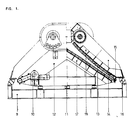
- Fig. 1 shows a cross-sectioned view of the vibrating machine on the left side and a view on the vibrating machine on the right side;
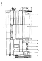
- Fig. 2 shows a lateral view of the vibrating machine on the left side, and a lateral section of the machine on the right side.
- The vibrating part of the machine, designed as the inverse letter "V", consists of two
main vibration frames 14, support frames ofupper impact plates 18 which are fitted to vibration frames, andimpact plate 13. - The vibrating part of the machine incorporates
hopper 1 for receiving the stone material. - The vibrating part of the machine is mounted through
vibration dampers 16 on thesupport frame 9. - The static part of the machine, shaped as equal-angled triangle, consists of
main frames 12, which support the support frame oflower impact plates 17 andimpact plates 13. Within the static part of the machine there is apressure flap 15 and apressure flap drive 10. The static part of the machine is mounted throughvibration mounts 11 onsupport frame 9. - The machine driving unit consists of an
electric motor support 4 withelectric motor 5, which through V-belts 8,speed reducer 7 andcardan joint shaft 6, drives thedriving shaft 2 withexcenter weight 3. - The machine driving unit is incorporated in the static part of the machine.
- The machine is called: Vibrating two-roof crusher.
- Special knowledge and experience are not needed for mounting upper and lower impact plates in two inclined surfaces and for driving upper impact plates in vertical vibrations.
- Impact plates must be made of friction resistant cast alloys.
- Dampers should be of high elasticity rubber.
-
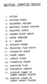
- 1. HOPPER
- 2. DRIVING SHAFT
- 3. EXCENTRIC WEIGHT
- 4. ELECTRIC MOTOR SUPPORT
- 5. ELECTRIC MOTOR
- 6. CARDAN JOINT SHAFT
- 7. SPEED REDUCER
- 8. V - BELTS
- 9. SUPPORT FRAME
- 10. PRESSURE FLAP DRIVE
- 11. VIBRATION MOUNT
- 12. FIXED FRAME
- 13. IMPACT PLATE
- 14. VIBRATION FRAME
- 15. PRESSURE FLAP
- 16. VIBRATION DAMPER
- 17. SUPPORT FRAME OF LOWER IMPACT PLATES
- 18. SUPPORT FRAME OF UPPER IMPACT PLATES
Claims (3)
1. Universal vibrating crusher, wherein it comprises two main vibration frames (14) mounted through vibration dampers (16) on steel frame (12) and strengthened by support frame (18) of upper impact plates (13) lined in two symmetrical inclined surfaces, and through bearings in the upper part of main frames two driving shafts (2) with excenter weights (3) are symmetrically placed, whereby the static part of the machine, mounted through vibration mounts (11) on steel frame (12) comprises frames (12) with support frames (17) of lower impact plates (13) lined also in two symmetrical inclined surfaces under slightly decreased angle in relation to upper impact plates, and at the ends of the static part of the machine, pressure flap (15) with pressure flap drive (10) is placed, and alongside is the electric motor support (4) with electric motor (5) connected by V-belt with the speed reducer (7) which through cardan joint shaft (6) drives the driving shaft and vibrating part of the machine.
2. Universal vibrating crusher, as claimed in claim 1, wherein said flap (15) with regulating pressure on the material going out, by means of pressure flap drive (10), is placed along outlet opening.
3. Universal vibrating crusher, as claimed in claim 1, wherein said upper vibrating part of the machine is mounted through vibration dampers (16) on steel frame (9) and said static part of the machine through vibration mounts (11).
Applications Claiming Priority (2)
| Application Number | Priority Date | Filing Date | Title |
|---|---|---|---|
| YU124388A YU124388A (en) | 1988-06-27 | 1988-06-27 | Universal vibrational crusher |
| YU1243/88 | 1988-06-27 |
Publications (2)
| Publication Number | Publication Date |
|---|---|
| EP0348830A2 true EP0348830A2 (en) | 1990-01-03 |
| EP0348830A3 EP0348830A3 (en) | 1991-01-30 |
Family
ID=25553367
Family Applications (1)
| Application Number | Title | Priority Date | Filing Date |
|---|---|---|---|
| EP19890111431 Withdrawn EP0348830A3 (en) | 1988-06-27 | 1989-06-23 | Universal vibrating crusher |
Country Status (2)
| Country | Link |
|---|---|
| EP (1) | EP0348830A3 (en) |
| YU (1) | YU124388A (en) |
Cited By (7)
| Publication number | Priority date | Publication date | Assignee | Title |
|---|---|---|---|---|
| RU2249484C2 (en) * | 2003-04-16 | 2005-04-10 | Кемеровский технологический институт пищевой промышленности | Method for grinding of bulk materials in cone vibratory grinder |
| RU2287372C1 (en) * | 2005-04-26 | 2006-11-20 | Федеральное государственное унитарное предприятие Сибирский научно-исследовательский институт геологии, геофизики и минерального сырья | Mincer |
| RU2292241C2 (en) * | 2005-03-09 | 2007-01-27 | Открытое Акционерное Общестов "НПК "Механобр-Техника" | Conical vibratory crusher with intersecting axes of vibration exciters |
| RU2688424C1 (en) * | 2018-02-15 | 2019-05-21 | Алексей Михайлович Левин | Grain grinder |
| CN111701675A (en) * | 2020-06-24 | 2020-09-25 | 铜仁学院 | A kind of automatic processing equipment of knotweed powder |
| RU2741635C1 (en) * | 2017-02-27 | 2021-01-28 | Фив Солиос | Conical crusher and method of grinding using such crusher |
| CN117816329A (en) * | 2023-12-29 | 2024-04-05 | 温州市嘉力新材料有限公司 | A processing technology of ethyl dicyanopropionate |
Family Cites Families (2)
| Publication number | Priority date | Publication date | Assignee | Title |
|---|---|---|---|---|
| GB491986A (en) * | 1936-05-09 | 1938-09-13 | Nordberg Manufacturing Co | Jaw crusher |
| DE2224823A1 (en) * | 1972-05-20 | 1973-11-29 | Franz Reimer | DEVICE FOR CRUSHING LITTLE OR TUBER-SHAPED GOODS |
-
1988
- 1988-06-27 YU YU124388A patent/YU124388A/en unknown
-
1989
- 1989-06-23 EP EP19890111431 patent/EP0348830A3/en not_active Withdrawn
Cited By (8)
| Publication number | Priority date | Publication date | Assignee | Title |
|---|---|---|---|---|
| RU2249484C2 (en) * | 2003-04-16 | 2005-04-10 | Кемеровский технологический институт пищевой промышленности | Method for grinding of bulk materials in cone vibratory grinder |
| RU2292241C2 (en) * | 2005-03-09 | 2007-01-27 | Открытое Акционерное Общестов "НПК "Механобр-Техника" | Conical vibratory crusher with intersecting axes of vibration exciters |
| RU2287372C1 (en) * | 2005-04-26 | 2006-11-20 | Федеральное государственное унитарное предприятие Сибирский научно-исследовательский институт геологии, геофизики и минерального сырья | Mincer |
| RU2741635C1 (en) * | 2017-02-27 | 2021-01-28 | Фив Солиос | Conical crusher and method of grinding using such crusher |
| RU2688424C1 (en) * | 2018-02-15 | 2019-05-21 | Алексей Михайлович Левин | Grain grinder |
| CN111701675A (en) * | 2020-06-24 | 2020-09-25 | 铜仁学院 | A kind of automatic processing equipment of knotweed powder |
| CN111701675B (en) * | 2020-06-24 | 2021-06-18 | 铜仁学院 | A kind of automatic processing equipment of knotweed powder |
| CN117816329A (en) * | 2023-12-29 | 2024-04-05 | 温州市嘉力新材料有限公司 | A processing technology of ethyl dicyanopropionate |
Also Published As
| Publication number | Publication date |
|---|---|
| YU124388A (en) | 1990-10-31 |
| EP0348830A3 (en) | 1991-01-30 |
Similar Documents
| Publication | Publication Date | Title |
|---|---|---|
| CA1081997A (en) | Vibratory material handling apparatus | |
| AU688367B2 (en) | Eccentric vibrating mill | |
| CA1191482A (en) | Sifter stroke screening unit | |
| US5094342A (en) | Vibratory conveyor | |
| EP0348830A2 (en) | Universal vibrating crusher | |
| CA2472174A1 (en) | Exciter mass assembly for a vibratory device | |
| US4007825A (en) | Vibratory parts feeder driven by rotating eccentric weights | |
| JPS6158363B2 (en) | ||
| KR20030041213A (en) | Apparatus for disparting ore in selection screen | |
| US4611709A (en) | Vibratory conveyor | |
| CN219816594U (en) | Jaw breaker with guide structure | |
| US5716162A (en) | Dual-stage mounting system for vibratory compactor drum | |
| US4428476A (en) | Vibratory apparatus | |
| JPH03106711A (en) | Straight type vibration feeder | |
| US5301814A (en) | Increasing the relative motion of a screen deck | |
| US5730297A (en) | Screening machine with improved base force reduction | |
| EP0272157A2 (en) | Crushing apparatus | |
| US3101315A (en) | Gyrating screen | |
| CN210357970U (en) | Special screen for shield mud-water separation system | |
| US3465976A (en) | Vibrating jaw crushers | |
| US4588137A (en) | Vibratory crusher | |
| CA1315252C (en) | Jaw crusher with multiple drive means | |
| US4756483A (en) | Jaw crusher with multiple drive means | |
| CN216174070U (en) | Superhard materials roller ball-milling sorting unit | |
| US2999651A (en) | Single stage rock crusher |
Legal Events
| Date | Code | Title | Description |
|---|---|---|---|
| PUAI | Public reference made under article 153(3) epc to a published international application that has entered the european phase |
Free format text: ORIGINAL CODE: 0009012 |
|
| AK | Designated contracting states |
Kind code of ref document: A2 Designated state(s): AT CH DE ES FR GB GR IT LI SE |
|
| PUAL | Search report despatched |
Free format text: ORIGINAL CODE: 0009013 |
|
| AK | Designated contracting states |
Kind code of ref document: A3 Designated state(s): AT CH DE ES FR GB GR IT LI SE |
|
| STAA | Information on the status of an ep patent application or granted ep patent |
Free format text: STATUS: THE APPLICATION IS DEEMED TO BE WITHDRAWN |
|
| 18D | Application deemed to be withdrawn |
Effective date: 19910731 |