EP0348714A2 - Device for adjustment and fastening of a spherical lens and method for using the device - Google Patents
Device for adjustment and fastening of a spherical lens and method for using the device Download PDFInfo
- Publication number
- EP0348714A2 EP0348714A2 EP89110473A EP89110473A EP0348714A2 EP 0348714 A2 EP0348714 A2 EP 0348714A2 EP 89110473 A EP89110473 A EP 89110473A EP 89110473 A EP89110473 A EP 89110473A EP 0348714 A2 EP0348714 A2 EP 0348714A2
- Authority
- EP
- European Patent Office
- Prior art keywords
- carrier
- base
- spherical lens
- legs
- optical waveguide
- Prior art date
- Legal status (The legal status is an assumption and is not a legal conclusion. Google has not performed a legal analysis and makes no representation as to the accuracy of the status listed.)
- Granted
Links
Images
Classifications
-
- G—PHYSICS
- G02—OPTICS
- G02B—OPTICAL ELEMENTS, SYSTEMS OR APPARATUS
- G02B6/00—Light guides; Structural details of arrangements comprising light guides and other optical elements, e.g. couplings
- G02B6/24—Coupling light guides
- G02B6/42—Coupling light guides with opto-electronic elements
- G02B6/4201—Packages, e.g. shape, construction, internal or external details
- G02B6/4204—Packages, e.g. shape, construction, internal or external details the coupling comprising intermediate optical elements, e.g. lenses, holograms
-
- G—PHYSICS
- G02—OPTICS
- G02B—OPTICAL ELEMENTS, SYSTEMS OR APPARATUS
- G02B6/00—Light guides; Structural details of arrangements comprising light guides and other optical elements, e.g. couplings
- G02B6/24—Coupling light guides
- G02B6/42—Coupling light guides with opto-electronic elements
- G02B6/4201—Packages, e.g. shape, construction, internal or external details
- G02B6/4219—Mechanical fixtures for holding or positioning the elements relative to each other in the couplings; Alignment methods for the elements, e.g. measuring or observing methods especially used therefor
- G02B6/422—Active alignment, i.e. moving the elements in response to the detected degree of coupling or position of the elements
- G02B6/4226—Positioning means for moving the elements into alignment, e.g. alignment screws, deformation of the mount
-
- G—PHYSICS
- G02—OPTICS
- G02B—OPTICAL ELEMENTS, SYSTEMS OR APPARATUS
- G02B6/00—Light guides; Structural details of arrangements comprising light guides and other optical elements, e.g. couplings
- G02B6/24—Coupling light guides
- G02B6/42—Coupling light guides with opto-electronic elements
- G02B6/4201—Packages, e.g. shape, construction, internal or external details
- G02B6/4219—Mechanical fixtures for holding or positioning the elements relative to each other in the couplings; Alignment methods for the elements, e.g. measuring or observing methods especially used therefor
- G02B6/422—Active alignment, i.e. moving the elements in response to the detected degree of coupling or position of the elements
- G02B6/4225—Active alignment, i.e. moving the elements in response to the detected degree of coupling or position of the elements by a direct measurement of the degree of coupling, e.g. the amount of light power coupled to the fibre or the opto-electronic element
-
- G—PHYSICS
- G02—OPTICS
- G02B—OPTICAL ELEMENTS, SYSTEMS OR APPARATUS
- G02B6/00—Light guides; Structural details of arrangements comprising light guides and other optical elements, e.g. couplings
- G02B6/24—Coupling light guides
- G02B6/42—Coupling light guides with opto-electronic elements
- G02B6/4201—Packages, e.g. shape, construction, internal or external details
- G02B6/4219—Mechanical fixtures for holding or positioning the elements relative to each other in the couplings; Alignment methods for the elements, e.g. measuring or observing methods especially used therefor
- G02B6/4236—Fixing or mounting methods of the aligned elements
- G02B6/4237—Welding
Definitions
- the invention relates to a device according to the preamble of claim 1.
- a device is e.g. known from the company publications of the Hewlett Packard "Miniature Fiber Optic Logic Link” HFBR-0200 Series, December 1981, Fig. 1 and "Optical fiber components for data transmission” 5953-7700 12/81, p.2.
- a photoelectric transmitter e.g. a light emitting diode to feed outgoing light directly into an optical waveguide, or the light emerging from an optical waveguide directly into a receiving module, e.g. a photodiode
- a receiving module e.g. a photodiode
- ball lenses are usually used, which are arranged in the respective transmitting or receiving module between the photoelectric components and the optical waveguides. Their task is to bundle the light emanating from a photoelectric transmission component and to feed it into the optical waveguide or to focus the light emerging from the optical waveguide onto a photoelectric receiving element.
- the ball lenses are held mechanically in a suspension of the transmitter or receiver module.
- the spherical lens To achieve the desired imaging properties, it is necessary for the spherical lens to be aligned with high precision between the respective light-electrical component and the optical waveguide. This alignment must be more precise, the higher the demands on the transmission system. For high-quality transmission systems, it is necessary to adjust the ball lenses in the transmitter and receiver modules.
- the object of the present invention is to provide a device according to the preamble of claim 1, which allows a ball lens to be arranged in a simple and economical manner in the transmitting or receiving module so that the required optical imaging properties can be achieved.
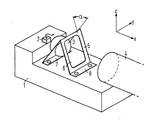
- the drawing schematically shows a base 1 arranged in the transmitting or receiving module of a photoelectric transmission path for receiving a photoelectric component 2 and a ball lens 3.
- the ball lens 3 is to be aligned and fixed between the photoelectric component 2 and an optical waveguide 4 so that the required optical imaging properties can be achieved.
- the ball lens 3 is fixed in a carrier 5, by means of which it can be aligned in all three coordinates X, Y and Z before or when it is fixed to the base 1.
- the carrier 5 consists of a band-shaped material which is angled transversely to its longitudinal axis and thereby forms two legs which collide in a V-shape.
- One leg of the carrier is provided with a recess for receiving the ball lens 3; the other has an opening 6 opposite this recess for the radiation emanating from or supplied to the photoelectric component 2.
- the ball lens 3 is mechanically fixed in the carrier 5 by suitable measures such as glazing, soldering, welding, gluing or pressing.
- the carrier has angled tabs 7 and 8 at the ends of the two legs, via which it is to be fastened to the base 1.
- the base 1 is flat in the area of the support 5 to be fastened to it.
- the attachment to the carrier is preferably carried out by welding the carrier tabs to the base.
- There is both Carrier as well as the base made of a weldable material, preferably a metal or a metal alloy.
- the process of adjusting and fixing a spherical lens proceeds as follows: First, the spherical lens 3 is to be aligned in the optical beam path by moving the carrier in the X and Y directions and adjusting the spreading angle ⁇ between the two legs of the carrier; this is determined by means of a suitable measuring apparatus. Then the leg of the carrier receiving the ball lens 3 is fixed to the base 1 by welding the leg to the base 1 via the angled tab 7; the welding points are indicated in the drawing by circles. The alignment or focusing of the radiation onto the optical waveguide or the photoelectric component is then checked and, if necessary, the height of the arrangement of the spherical lens is corrected by adjusting the spreading angle ⁇ between the two legs of the carrier 5.
- the other leg of the carrier 5 is welded to the base 1.
- the carrier is preferably applied to the base and the carrier is adjusted using a gripping tool for the sensitive positioning and adjustment of the carrier.
- the spherical lens is mechanically fixed in the beam path between the photoelectric component and the optical waveguide.
- the particular advantage of the device according to the invention can be seen in the fact that the highly precise adjustment and fixing of a spherical lens using a carrier designed as an inexpensive stamping / stamping part is possible with only low tolerance requirements.
- the spot welds of the carrier and the base require only a very short service life of the gripping tool during the fixing process.
- the thermal load on the surrounding structures during the welding process is low; A possible welding delay when welding the first carrier leg can be compensated for by readjusting the carrier.
- several devices, each with a spherical lens can be in the transmission Arrange or receive module of a photoelectric transmission path.
Abstract
Description
Die Erfindung bezieht sich auf eine Vorrichtung nach dem Oberbegriff des Patentanspruches 1. Eine derartige Vorrichtung ist z.B. aus den Firmendruckschriften der Hewlett Packard "Miniature Fibre Optic Logic Link" HFBR-0200 Series, Dezember 1981, Fig. 1 und "Lichtwellenleiterkomponenten zur Datenübertragung" 5953-7700 12/81, S.2 bekannt.The invention relates to a device according to the preamble of claim 1. Such a device is e.g. known from the company publications of the Hewlett Packard "Miniature Fiber Optic Logic Link" HFBR-0200 Series, December 1981, Fig. 1 and "Optical fiber components for data transmission" 5953-7700 12/81, p.2.
Bei der Datenübertragung über Lichtwellenleiter reicht es im allgemeinen nicht aus, das von einem lichtelektrischen Sendebaustein, z.B. einer Leuchtdiode, ausgehende Licht direkt in einen Lichtwellenleiter einzuspeisen, bzw. das aus einem Lichtwellenleiter austretende Licht direkt einem Empfangsbaustein, z.B. einer Fotodiode, zuzuführen, sondern es sind zusätzlich optische Mittel im Strahlengang des Sende- bzw. Empfangselementes anzuordnen, welche die Verluste beim Ein- bzw. Auskoppeln der Strahlung in bzw. aus dem Lichtwellenleiter möglichst gering halten. Hierzu werden üblicherweise Kugellinsen verwendet, die im jeweiligen Sende- bzw. Empfangsbaustein zwischen den lichtelektrischen Bauelementen und den Lichtwellenleitern angeordnet sind. Ihre Aufgabe ist es, das von einem lichtelektrischen Sendebauelement ausgehende Licht zu bündeln und in den Lichtwellenleiter einzuspeisen bzw. das aus dem Lichtwellenleiter austretende Licht auf ein lichtelektrisches Empfangselement zu fokussieren. Die Kugellinsen sind dabei in einer Aufhängung des Sende- bzw. Empfangsbausteines mechanisch gehalten.In the case of data transmission via optical fibers, it is generally not sufficient to use a photoelectric transmitter, e.g. a light emitting diode to feed outgoing light directly into an optical waveguide, or the light emerging from an optical waveguide directly into a receiving module, e.g. a photodiode, but there are additional optical means to be arranged in the beam path of the transmitting or receiving element, which keep the losses when coupling or decoupling the radiation into or out of the optical waveguide as low as possible. For this purpose, ball lenses are usually used, which are arranged in the respective transmitting or receiving module between the photoelectric components and the optical waveguides. Their task is to bundle the light emanating from a photoelectric transmission component and to feed it into the optical waveguide or to focus the light emerging from the optical waveguide onto a photoelectric receiving element. The ball lenses are held mechanically in a suspension of the transmitter or receiver module.
Zum Erzielen der gewünschten Abbildungseigenschaften ist es notwendig, daß die Kugellinse zwischen dem jeweiligen licht-elektrischen Bauelement und dem Lichtwellenleiter hochgenau ausgerichtet ist. Diese Ausrichtung muß um so genauer sein, je höher die Anforderungen an das Übertragungssystem sind. Für Übertragungssysteme hoher Güte ist ein Justieren der Kugellinsen in den Sende- bzw. Empfangsbausteinen erforderlich.To achieve the desired imaging properties, it is necessary for the spherical lens to be aligned with high precision between the respective light-electrical component and the optical waveguide. This alignment must be more precise, the higher the demands on the transmission system. For high-quality transmission systems, it is necessary to adjust the ball lenses in the transmitter and receiver modules.
Aufgabe der vorliegenden Erfindung ist es, eine Vorrichtung nach dem Oberbegriff des Patentanspruches 1 anzugeben, die es gestattet, eine Kugellinse auf einfache und wirtschaftliche Weise so im Sende- bzw. Empfangsbaustein anzuordnen, daß die geforderten optischen Abbildungseigenschaften erreichbar sind.The object of the present invention is to provide a device according to the preamble of claim 1, which allows a ball lens to be arranged in a simple and economical manner in the transmitting or receiving module so that the required optical imaging properties can be achieved.
Die Erfindung löst diese Aufgabe durch die kennzeichnenden Merkmale des Patentanspruches 1. Vorteilhafte Ausbildungen der erfindungsgemäßen Vorrichtung sind in den Unteransprüchen 2 und 3 angegeben. Die Ansprüche 4 bis 6 betreffen ein Verfahren zum Betrieb der Vorrichtung nach den Ansprüchen 1, 2 oder 3. Die Erfindung ist nachstehend anhand eines in der Zeichnung dargestellten Ausführungsbeispieles näher erläutert.The invention solves this problem by the characterizing features of patent claim 1. Advantageous embodiments of the device according to the invention are specified in subclaims 2 and 3. Claims 4 to 6 relate to a method for operating the device according to claims 1, 2 or 3. The invention is explained in more detail below with reference to an embodiment shown in the drawing.
Die Zeichnung zeigt schematisch eine im Sende- bzw. Empfangsbaustein einer lichtelektrischen Übertragungsstrecke angeordnete Unterlage 1 zur Aufnahme eines lichtelektrischen Bauelementes 2 und einer Kugellinse 3. Die Kugellinse 3 ist zwischen dem lichtelektrischen Bauelement 2 und einem Lichtwellenleiter 4 so auszurichten und zu fixieren, daß die geforderten optischen Abbildungseigenschaften erreicht werden. Hierzu ist die Kugellinse 3 in einem Träger 5 festgelegt, über den sie vor bzw. bei dessen Fixierung an der Unterlage 1 in allen drei Koordinaten X, Y und Z ausgerichtet werden kann. Der Träger 5 besteht aus einem bandförmigen Material, das quer zu seiner Längsachse abgewinkelt ist und dabei zwei Schenkel bildet, die V-förmig zusammenstoßen. Der eine Schenkel des Trägers ist mit einer Ausnehmung zur Aufnahme der Kugellinse 3 versehen; der andere weist einen dieser Ausnehmung gegenüberliegenden Durchbruch 6 für die vom lichtelektrischen Bauelement 2 ausgehende bzw. diesem zugeführte Strahlung auf. Die Kugellinse 3 ist im Träger 5 durch geeignete Maßnahmen wie Einglasen, Einlöten, Einschweißen, Einkleben oder Einpressen mechanisch fixiert. Der Träger weist an den Enden der beiden Schenkel abgewinkelte Laschen 7 und 8 auf, über die er an der Unterlage 1 zu befestigen ist. Die Unterlage 1 ist im Bereich des an ihr zu befestigenden Trägers 5 eben ausgeführt. Die Befestigung am Träger erfolgt vorzugsweise durch Verschweißen der Trägerlaschen mit der Unterlage. Hierzu besteht sowohl der Träger als auch die Unterlage aus einem schweißbaren Material, vorzugsweise einem Metall oder einer Metallegierung.The drawing schematically shows a base 1 arranged in the transmitting or receiving module of a photoelectric transmission path for receiving a photoelectric component 2 and a ball lens 3. The ball lens 3 is to be aligned and fixed between the photoelectric component 2 and an optical waveguide 4 so that the required optical imaging properties can be achieved. For this purpose, the ball lens 3 is fixed in a carrier 5, by means of which it can be aligned in all three coordinates X, Y and Z before or when it is fixed to the base 1. The carrier 5 consists of a band-shaped material which is angled transversely to its longitudinal axis and thereby forms two legs which collide in a V-shape. One leg of the carrier is provided with a recess for receiving the ball lens 3; the other has an opening 6 opposite this recess for the radiation emanating from or supplied to the photoelectric component 2. The ball lens 3 is mechanically fixed in the carrier 5 by suitable measures such as glazing, soldering, welding, gluing or pressing. The carrier has angled tabs 7 and 8 at the ends of the two legs, via which it is to be fastened to the base 1. The base 1 is flat in the area of the support 5 to be fastened to it. The attachment to the carrier is preferably carried out by welding the carrier tabs to the base. There is both Carrier as well as the base made of a weldable material, preferably a metal or a metal alloy.
Der Vorgang des Justierens und Fixierens einer Kugellinse geht folgendermaßen vor sich: Zunächst ist die Kugellinse 3 durch Verschieben des Trägers in X- und Y-Richtung und Einstellen des Spreizwinkels α zwischen den beiden Schenkeln des Trägers im optischen Strahlengang auszurichten; dies wird mittels einer geeigneten Meßapparatur festgestellt. Sodann wird der die Kugellinse 3 aufnehmende Schenkel des Trägers an der Unterlage 1 fixiert, indem der Schenkel über die abgewinkelte Lasche 7 mit der Unterlage 1 verschweißt wird; die Schweißpunkte sind in der Zeichnung durch Kreise angedeutet. Anschließend wird die Ausrichtung bzw. Fokussierung der Strahlung auf den Lichtwellenleiter bzw. das lichtelektrische Bauelement kontrolliert und, sofern es erforderlich ist, wird die Anordnung der Kugellinse in ihrer Höhe durch Einstellen des Spreizwinkels α zwischen den beiden Schenkeln des Trägers 5 korrigiert. Anschließend wird auch der andere Schenkel des Trägers 5 mit der Unterlage 1 verschweißt. Das Aufbringen des Trägers auf die Unterlage und das Justieren des Trägers erfolgt vorzugsweise über ein Greifwerkzeug zur feinfühligen Positionierung und Einstellung des Trägers. Nach dem Verschweißen des Trägers mit der Unterlage 1 ist die Kugellinse im Strahlengang zwischen lichtelektrischem Bauelement und Lichtwellenleiter mechanisch fixiert.The process of adjusting and fixing a spherical lens proceeds as follows: First, the spherical lens 3 is to be aligned in the optical beam path by moving the carrier in the X and Y directions and adjusting the spreading angle α between the two legs of the carrier; this is determined by means of a suitable measuring apparatus. Then the leg of the carrier receiving the ball lens 3 is fixed to the base 1 by welding the leg to the base 1 via the angled tab 7; the welding points are indicated in the drawing by circles. The alignment or focusing of the radiation onto the optical waveguide or the photoelectric component is then checked and, if necessary, the height of the arrangement of the spherical lens is corrected by adjusting the spreading angle α between the two legs of the carrier 5. Then the other leg of the carrier 5 is welded to the base 1. The carrier is preferably applied to the base and the carrier is adjusted using a gripping tool for the sensitive positioning and adjustment of the carrier. After the support has been welded to the base 1, the spherical lens is mechanically fixed in the beam path between the photoelectric component and the optical waveguide.
Der besondere Vorteil der erfindungsgemäßen Vorrichtung ist darin zu sehen, daß das hochgenaue Justieren und Fixieren einer Kugellinse unter Verwendung eines als kostengünstiges Stanz/Prägeteil ausgebildeten Träger mit nur geringen Toleranzanforderungen möglich ist. Die Punktschweißungen von Träger und Unterlage erfordern nur sehr kurze Standzeiten des Greifwerkzeuges während des Fixiervorganges. Die thermische Belastung der umgebenden Strukturen während des Schweißvorganges ist gering; ein eventueller Schweißverzug beim Verschweißen des ersten Trägerschenkels kann durch Nachjustieren des Trägers aufgefangen werden. Gegebenenfalls lassen sich auch mehrere, mit je einer Kugellinse versehene Vorrichtungen im Sende bzw. Empfangsbaustein einer lichtelektrischen Übertragungsstrecke anordnen.The particular advantage of the device according to the invention can be seen in the fact that the highly precise adjustment and fixing of a spherical lens using a carrier designed as an inexpensive stamping / stamping part is possible with only low tolerance requirements. The spot welds of the carrier and the base require only a very short service life of the gripping tool during the fixing process. The thermal load on the surrounding structures during the welding process is low; A possible welding delay when welding the first carrier leg can be compensated for by readjusting the carrier. If necessary, several devices, each with a spherical lens, can be in the transmission Arrange or receive module of a photoelectric transmission path.
Claims (6)
Applications Claiming Priority (2)
| Application Number | Priority Date | Filing Date | Title |
|---|---|---|---|
| DE3822389 | 1988-07-01 | ||
| DE3822389 | 1988-07-01 |
Publications (3)
| Publication Number | Publication Date |
|---|---|
| EP0348714A2 true EP0348714A2 (en) | 1990-01-03 |
| EP0348714A3 EP0348714A3 (en) | 1990-09-26 |
| EP0348714B1 EP0348714B1 (en) | 1993-09-01 |
Family
ID=6357798
Family Applications (1)
| Application Number | Title | Priority Date | Filing Date |
|---|---|---|---|
| EP89110473A Expired - Lifetime EP0348714B1 (en) | 1988-07-01 | 1989-06-09 | Device for adjustment and fastening of a spherical lens and method for using the device |
Country Status (2)
| Country | Link |
|---|---|
| EP (1) | EP0348714B1 (en) |
| DE (1) | DE58905432D1 (en) |
Cited By (1)
| Publication number | Priority date | Publication date | Assignee | Title |
|---|---|---|---|---|
| EP0779526A3 (en) * | 1995-12-13 | 1997-10-29 | Deutsche Telekom Ag | Optical and/or electrooptical connection and process for its fabrication |
Citations (4)
| Publication number | Priority date | Publication date | Assignee | Title |
|---|---|---|---|---|
| US3950075A (en) * | 1974-02-06 | 1976-04-13 | Corning Glass Works | Light source for optical waveguide bundle |
| EP0021473A1 (en) * | 1979-05-31 | 1981-01-07 | Koninklijke Philips Electronics N.V. | Coupling element comprising a light source and a lens-shaped element |
| DE3300902A1 (en) * | 1983-01-13 | 1984-07-19 | Hewlett-Packard GmbH, 7030 Böblingen | Semiconductor laser having a colliminating lens and method for producing the housing upper part |
| US4793688A (en) * | 1986-05-26 | 1988-12-27 | Hitachi Ltd. | Photo electro device, method for manufacture of same, and lens support frame for use in such photo electro device |
-
1989
- 1989-06-09 EP EP89110473A patent/EP0348714B1/en not_active Expired - Lifetime
- 1989-06-09 DE DE89110473T patent/DE58905432D1/en not_active Expired - Fee Related
Patent Citations (4)
| Publication number | Priority date | Publication date | Assignee | Title |
|---|---|---|---|---|
| US3950075A (en) * | 1974-02-06 | 1976-04-13 | Corning Glass Works | Light source for optical waveguide bundle |
| EP0021473A1 (en) * | 1979-05-31 | 1981-01-07 | Koninklijke Philips Electronics N.V. | Coupling element comprising a light source and a lens-shaped element |
| DE3300902A1 (en) * | 1983-01-13 | 1984-07-19 | Hewlett-Packard GmbH, 7030 Böblingen | Semiconductor laser having a colliminating lens and method for producing the housing upper part |
| US4793688A (en) * | 1986-05-26 | 1988-12-27 | Hitachi Ltd. | Photo electro device, method for manufacture of same, and lens support frame for use in such photo electro device |
Cited By (1)
| Publication number | Priority date | Publication date | Assignee | Title |
|---|---|---|---|---|
| EP0779526A3 (en) * | 1995-12-13 | 1997-10-29 | Deutsche Telekom Ag | Optical and/or electrooptical connection and process for its fabrication |
Also Published As
| Publication number | Publication date |
|---|---|
| DE58905432D1 (en) | 1993-10-07 |
| EP0348714B1 (en) | 1993-09-01 |
| EP0348714A3 (en) | 1990-09-26 |
Similar Documents
| Publication | Publication Date | Title |
|---|---|---|
| DE2924119C2 (en) | Coupling element with a light source and a lens | |
| DE3914835C1 (en) | ||
| DE60025052T2 (en) | Device for adjusting a light source with an optical fiber and an optical module containing the same | |
| EP2073047B1 (en) | An assembly and alignment method for an electro-optical device and a measuring device assembled and aligned according to the method | |
| DE60210010T2 (en) | Collimation system for laser diode | |
| EP0990931B1 (en) | Device for coupling light into and out of waveguides and method of its production | |
| DE19823934A1 (en) | Device for coupling a light source to an optical fiber | |
| DE19502264C2 (en) | Module for an optical connection | |
| EP0992823B1 (en) | Method for aligning an electrooptical component | |
| DE19524475C1 (en) | Optical centring unit for positioning SMD semiconductor element, or a laser diode, on substrate | |
| DE3138296A1 (en) | METHOD FOR POSITIONING AND FIXING OPTICAL COMPONENTS RELATIVELY TO OTHER | |
| DE4344899A1 (en) | Rotation and alignment device for assembling a fiber optic connector with lower connector losses | |
| EP0590393A1 (en) | Semiconductor laser module | |
| DE4235549A1 (en) | Light source unit, e.g. for laser printer or copier - contains multiple light emitting semiconductor laser chips arranged in mounting device to emit parallel light beams through collimator lens | |
| DE4009380A1 (en) | LASER MODULE | |
| EP1913415B1 (en) | Distance measuring equipment, and method for mounting an electrooptical unit on a lead frame unit | |
| EP0348714B1 (en) | Device for adjustment and fastening of a spherical lens and method for using the device | |
| DE102004059945B4 (en) | Transmitter and receiver for high-tolerance optical fiber transmission | |
| DE2922452C2 (en) | Laser unit | |
| EP0388679A1 (en) | Method for aligning and fixing a lens and optical coupling arrangement fabricated therewith | |
| DE3413749C2 (en) | ||
| WO1998035252A1 (en) | Laser module with coupling optics and method for fine-adjustment of said optics | |
| DE19751378B4 (en) | Method and device for producing a scanning device for optical recording media | |
| DE2954697C2 (en) | Laser recording system for graphical information | |
| DE3829350C2 (en) |
Legal Events
| Date | Code | Title | Description |
|---|---|---|---|
| PUAI | Public reference made under article 153(3) epc to a published international application that has entered the european phase |
Free format text: ORIGINAL CODE: 0009012 |
|
| AK | Designated contracting states |
Kind code of ref document: A2 Designated state(s): DE FR GB IT |
|
| PUAL | Search report despatched |
Free format text: ORIGINAL CODE: 0009013 |
|
| AK | Designated contracting states |
Kind code of ref document: A3 Designated state(s): DE FR GB IT |
|
| 17P | Request for examination filed |
Effective date: 19900828 |
|
| 17Q | First examination report despatched |
Effective date: 19920814 |
|
| GRAA | (expected) grant |
Free format text: ORIGINAL CODE: 0009210 |
|
| AK | Designated contracting states |
Kind code of ref document: B1 Designated state(s): DE FR GB IT |
|
| PG25 | Lapsed in a contracting state [announced via postgrant information from national office to epo] |
Ref country code: IT Free format text: LAPSE BECAUSE OF FAILURE TO SUBMIT A TRANSLATION OF THE DESCRIPTION OR TO PAY THE FEE WITHIN THE PRE;WARNING: LAPSES OF ITALIAN PATENTS WITH EFFECTIVE DATE BEFORE 2007 MAY HAVE OCCURRED AT ANY TIME BEFORE 2007. THE CORRECT EFFECTIVE DATE MAY BE DIFFERENT FROM THE ONE RECORDED.SCRIBED TIME-LIMIT Effective date: 19930901 Ref country code: GB Effective date: 19930901 Ref country code: FR Effective date: 19930901 |
|
| REF | Corresponds to: |
Ref document number: 58905432 Country of ref document: DE Date of ref document: 19931007 |
|
| EN | Fr: translation not filed | ||
| GBV | Gb: ep patent (uk) treated as always having been void in accordance with gb section 77(7)/1977 [no translation filed] |
Effective date: 19930901 |
|
| PLBE | No opposition filed within time limit |
Free format text: ORIGINAL CODE: 0009261 |
|
| STAA | Information on the status of an ep patent application or granted ep patent |
Free format text: STATUS: NO OPPOSITION FILED WITHIN TIME LIMIT |
|
| 26N | No opposition filed | ||
| PG25 | Lapsed in a contracting state [announced via postgrant information from national office to epo] |
Ref country code: DE Effective date: 19950301 |