EP0348418B1 - Refiner segment - Google Patents
Refiner segment Download PDFInfo
- Publication number
- EP0348418B1 EP0348418B1 EP88902253A EP88902253A EP0348418B1 EP 0348418 B1 EP0348418 B1 EP 0348418B1 EP 88902253 A EP88902253 A EP 88902253A EP 88902253 A EP88902253 A EP 88902253A EP 0348418 B1 EP0348418 B1 EP 0348418B1
- Authority
- EP
- European Patent Office
- Prior art keywords
- bars
- grooves
- apertures
- refiner
- refiner segment
- Prior art date
- Legal status (The legal status is an assumption and is not a legal conclusion. Google has not performed a legal analysis and makes no representation as to the accuracy of the status listed.)
- Expired - Lifetime
Links
- 239000000463 material Substances 0.000 claims description 7
- 238000007670 refining Methods 0.000 claims description 7
- 239000000835 fiber Substances 0.000 claims description 4
- 230000015572 biosynthetic process Effects 0.000 description 1
- 230000007423 decrease Effects 0.000 description 1
- 239000012895 dilution Substances 0.000 description 1
- 238000010790 dilution Methods 0.000 description 1
- 239000000243 solution Substances 0.000 description 1
- XLYOFNOQVPJJNP-UHFFFAOYSA-N water Substances O XLYOFNOQVPJJNP-UHFFFAOYSA-N 0.000 description 1
- 239000002023 wood Substances 0.000 description 1
Images
Classifications
-
- D—TEXTILES; PAPER
- D21—PAPER-MAKING; PRODUCTION OF CELLULOSE
- D21D—TREATMENT OF THE MATERIALS BEFORE PASSING TO THE PAPER-MAKING MACHINE
- D21D1/00—Methods of beating or refining; Beaters of the Hollander type
- D21D1/20—Methods of refining
- D21D1/30—Disc mills
- D21D1/306—Discs
Definitions
- This invention relates to refiner segments in a disc refiner for refining fibre material, which can be wood chips or pulp, which is entirely or partially defibered.
- the disc refiner comprises two opposed refiner discs, one or both of which can be rotatable.
- refiner segments are located, which are formed with a pattern of bars and intermediate grooves.
- the refiner discs are positioned so that the refiner segments form a disc gap, through which the fibre material is intended to pass, whereby the refining is carried out by the bars of the refiner segments.
- a segment according to the preamble of claim 1 is known from FR-A-1 189 470.
- the bars and grooves of the refiner segments normally extend substantially radially.
- the pattern can be divided into different zones located outside each other.
- One way of solving the aforesaid problem is to supply dilution water to the disc gap in order thereby to condense the steam. This way, however, causes a reduction in the material concentration to such a low level that the pulp quality deteriorates.
- the bars on the refiner segment are formed with apertures, which interconnect adjacent grooves, so that the grooves communicate freely outward and inward via the apertures.
- the steam developed is not obstructed by the cross bars, but can flow through the apertures to the adjacent groove and further outward or inward.
- the steam pressure resulting in the disc gap increases in the outward direction to a maximum and thereafter decreases toward the outlet of the disc gap. This implies, that steam formed in the interior part of the disc gap, i.e. inside of said pressure maximum, flows inward, while steam forming in the outer part of the disc gap flows outward to the outlet of the disc gap.
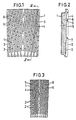
- FIG. 1 shows a refiner segment seen perpendicularly to the surface
- Fig. 2 is a section along II-II in Fig. 1
- Fig. 3 shows another embodiment of a refiner segment.
- Refiner segments 1 are formed with a pattern of substantially radial bars and intermediate grooves.
- the pattern is divided into two zones, an inner one and an outer one.
- the bars 2 and grooves 3 in the inner zone are coarser than the bars 4 and grooves 5 in the outer zone.
- flow restrictions 6 are located in the outer zone.
- flow restrictions 7 are provided also in the inner zone, but such restrictions are not provided at the embodiment shown in Fig. 3.
- the flow restrictions 7 in the inner zone do not extend all the way to the upper surface of the bars 2, while the flow restrictions 6 in the outer zone extend up to the level of the upper surface of the bars 4.
- the grooves 5 communicate with each other through apertures 8 in intermediate bars 4.
- Each of these apertures 8 is located in close connection to a flow restriction 6 and in radial direction outside the same.
- the apertures 8 preferably are U-shaped and extend a distance downward from the upper surface of the bars 4.
- the apertures 8 are located so that there is free communication both outward and inward via the apertures 8 and grooves 5.
- the steam development during the refining is especially high in the outer zone where the steam pressure maximum is located.
- the apertures 8, therefore, provide a possible passage for the steam over to adjacent grooves 5, in which the steam can continue to flow outward or inward and possibly via additional apertures 8 and grooves 5 finally leave the disc gap at the outlet or inlet thereof.
- each aperture 8 and flow restrictions 6 are located so, that each aperture is located, counted in radial direction, immediately outside a flow restriction in a groove and immediately inside a flow restriction in adjacent grooves.
- the return flow of the steam through grooves is thereby minimized, because it is obstructed by the flow restrictions.
Landscapes
- Paper (AREA)
- Crushing And Grinding (AREA)
- Polishing Bodies And Polishing Tools (AREA)
- Agricultural Chemicals And Associated Chemicals (AREA)
- Cosmetics (AREA)
- Solid-Sorbent Or Filter-Aiding Compositions (AREA)
Abstract
Description
- This invention relates to refiner segments in a disc refiner for refining fibre material, which can be wood chips or pulp, which is entirely or partially defibered. The disc refiner comprises two opposed refiner discs, one or both of which can be rotatable. On the refiner discs refiner segments are located, which are formed with a pattern of bars and intermediate grooves. The refiner discs are positioned so that the refiner segments form a disc gap, through which the fibre material is intended to pass, whereby the refining is carried out by the bars of the refiner segments.
- A segment according to the preamble of
claim 1 is known from FR-A-1 189 470. - The bars and grooves of the refiner segments normally extend substantially radially. The pattern can be divided into different zones located outside each other.
- At the refining of fibre material with high concentration, and especially at high energy charges, it was found necessary to insert flow restrictions, so-called cross-bars, in the grooves in the refiner segments in order to prevent unprocessed material to pass out through the disc gap. These cross bars, however, constitute a hinder for the steam, which during the refining develops in the disc gap. Thereby a high steam pressure arises in the disc gap. This high steam pressure has a negative effect on the capacity and operation stability of the refiner, and it also limits the possible energy charge. The steam developed, thus, is forced upward out of the grooves by the flow restrictions and disturbs the material flow through the disc gap.
- One way of solving the aforesaid problem is to supply dilution water to the disc gap in order thereby to condense the steam. This way, however, causes a reduction in the material concentration to such a low level that the pulp quality deteriorates.
- The present invention provides in the characterising of claim 1 a solution of the problem of high steam pressure in the disc gap, without giving rise to other inconveniencies at the refining. According to the invention, the bars on the refiner segment are formed with apertures, which interconnect adjacent grooves, so that the grooves communicate freely outward and inward via the apertures. This implies, that the steam developed is not obstructed by the cross bars, but can flow through the apertures to the adjacent groove and further outward or inward. The steam pressure resulting in the disc gap increases in the outward direction to a maximum and thereafter decreases toward the outlet of the disc gap. This implies, that steam formed in the interior part of the disc gap, i.e. inside of said pressure maximum, flows inward, while steam forming in the outer part of the disc gap flows outward to the outlet of the disc gap.
- The invention is described in greater detail in the following, with reference to the accompanying drawing showing two embodiments of a refiner segment according to the invention, in which drawing Fig. 1 shows a refiner segment seen perpendicularly to the surface, Fig. 2 is a section along II-II in Fig. 1, and Fig. 3 shows another embodiment of a refiner segment.
-
Refiner segments 1 according to the Figures are formed with a pattern of substantially radial bars and intermediate grooves. The pattern is divided into two zones, an inner one and an outer one. Thebars 2 andgrooves 3 in the inner zone are coarser than the bars 4 andgrooves 5 in the outer zone. In the outerzone flow restrictions 6 are located. At the embodiment according to Figs. 1 and 2 flow restrictions 7 are provided also in the inner zone, but such restrictions are not provided at the embodiment shown in Fig. 3. The flow restrictions 7 in the inner zone do not extend all the way to the upper surface of thebars 2, while theflow restrictions 6 in the outer zone extend up to the level of the upper surface of the bars 4. In the outer zone thegrooves 5 communicate with each other throughapertures 8 in intermediate bars 4. Each of theseapertures 8 is located in close connection to aflow restriction 6 and in radial direction outside the same. Theapertures 8 preferably are U-shaped and extend a distance downward from the upper surface of the bars 4. - The
apertures 8 are located so that there is free communication both outward and inward via theapertures 8 andgrooves 5. The steam development during the refining is especially high in the outer zone where the steam pressure maximum is located. Theapertures 8, therefore, provide a possible passage for the steam over toadjacent grooves 5, in which the steam can continue to flow outward or inward and possibly viaadditional apertures 8 andgrooves 5 finally leave the disc gap at the outlet or inlet thereof. - At the embodiment according to Fig. 3 the
apertures 8 andflow restrictions 6 are located so, that each aperture is located, counted in radial direction, immediately outside a flow restriction in a groove and immediately inside a flow restriction in adjacent grooves. The return flow of the steam through grooves is thereby minimized, because it is obstructed by the flow restrictions. - In cases when the refiner segment is formed with more zones the apertures in the first hand should be placed in the outermost, zone where they will be most useful due to the great steam formation in said zone.
Claims (4)
- A refiner segment for disk refiners for the refining of fibre material, which segment is formed with a pattern of bars (4) and intermediate grooves (5), which extend substantially radially, and where flow restrictions (6) extending to the level of the upper surfaces of the bars (4) are located in the grooves (5), and the grooves (5) intercommunicate through apertures (8) in intermediate bars (4),
characterized in that said apertures (8) being located in close connection to and radially outside a flow restriction (6) and that the grooves (5) together with the apertures (8) constitute a free passage below the upper surface of the bars (4) over the entire refiner segment. - A refiner segment as defined in claim 1,
characterized in that each aperture (8) is located, counted in radial direction, immediately outside a flow restriction (6) in a groove (5) and immediately inside a flow restriction (6) in adjacent groove (5). - A refiner segment as defined in claim 1 or 2, characterized in that the apertures (8) are U-shaped and extend a distance downward from the upper surface of the bars (4).
- A refiner segment as defined in any one of the preceding claims, characterized in that the pattern is divided into different zones located outside each other, and the apertures (8) are located in connection to the flow restrictions (6) in at least the outermost zone.
Applications Claiming Priority (2)
| Application Number | Priority Date | Filing Date | Title |
|---|---|---|---|
| SE8700790 | 1987-02-25 | ||
| SE8700790A SE456223B (en) | 1987-02-25 | 1987-02-25 | DISC REFINOR PAINTING ELEMENT |
Publications (2)
| Publication Number | Publication Date |
|---|---|
| EP0348418A1 EP0348418A1 (en) | 1990-01-03 |
| EP0348418B1 true EP0348418B1 (en) | 1992-09-23 |
Family
ID=20367665
Family Applications (1)
| Application Number | Title | Priority Date | Filing Date |
|---|---|---|---|
| EP88902253A Expired - Lifetime EP0348418B1 (en) | 1987-02-25 | 1988-02-23 | Refiner segment |
Country Status (11)
| Country | Link |
|---|---|
| US (1) | US4953796A (en) |
| EP (1) | EP0348418B1 (en) |
| JP (1) | JP2592515B2 (en) |
| AU (1) | AU1392088A (en) |
| CA (1) | CA1297329C (en) |
| DE (1) | DE3874888T2 (en) |
| FI (1) | FI87149C (en) |
| NO (1) | NO172567C (en) |
| NZ (1) | NZ223610A (en) |
| SE (1) | SE456223B (en) |
| WO (1) | WO1988006490A1 (en) |
Families Citing this family (23)
| Publication number | Priority date | Publication date | Assignee | Title |
|---|---|---|---|---|
| US5039022A (en) * | 1989-09-05 | 1991-08-13 | Kamyr Ab | Refiner element pattern achieving successive compression before impact |
| US5085735A (en) * | 1989-09-05 | 1992-02-04 | Kamyr Ab | Method of refining cellulosic fibrous material with successive expansions before impacts, and expansions, to achieve increased fiber flexibility |
| AU116198S (en) | 1992-01-28 | 1993-01-22 | Sunds Defibrator Ind Aktiebolag | Refining plate |
| SE501378C2 (en) * | 1993-06-17 | 1995-01-30 | Sunds Defibrator Ind Ab | Grinding elements for disc refiners for atomizing lignocellulosic material |
| US5467931A (en) * | 1994-02-22 | 1995-11-21 | Beloit Technologies, Inc. | Long life refiner disc |
| US5476228A (en) * | 1994-03-07 | 1995-12-19 | Beloit Technologies, Inc. | Refiner disk with alternating depth grooves |
| US5823453A (en) * | 1995-11-14 | 1998-10-20 | J & L Fiber Services, Inc. | Refiner disc with curved refiner bars |
| SE508286C2 (en) * | 1997-01-31 | 1998-09-21 | Sunds Defibrator Ind Ab | Grinding elements for disc refiners with booms and intermediate tracks and channels for free passage of steam |
| US5863000A (en) * | 1997-07-01 | 1999-01-26 | Durametal Corporation | Refiner plate with steam relief pockets |
| US5893525A (en) * | 1997-07-01 | 1999-04-13 | Durametal Corporation | Refiner plate with variable pitch |
| US5944271A (en) * | 1997-08-28 | 1999-08-31 | J&L Fiber Services, Inc. | High consistency damless refiner plate for wood fibers |
| US5988538A (en) * | 1998-07-28 | 1999-11-23 | J&L Fiber Services, Inc. | Refiner disc having steam exhaust channel |
| KR20010106423A (en) * | 1998-08-19 | 2001-11-29 | 추후 | Refiner plate with chicanes |
| US6032888A (en) * | 1999-04-16 | 2000-03-07 | Durametal Corporation | Refiner plate with interspersed surface and subsurface dams |
| US6325308B1 (en) | 1999-09-28 | 2001-12-04 | J & L Fiber Services, Inc. | Refiner disc and method |
| JP4273772B2 (en) * | 2003-01-23 | 2009-06-03 | 日本製紙株式会社 | Chemi-thermomechanical pulp and its production method and use |
| US9968938B2 (en) | 2012-09-17 | 2018-05-15 | Andritz Inc. | Refiner plate with gradually changing geometry |
| DE102013000593A1 (en) | 2013-01-16 | 2014-07-17 | Cvp Clean Value Plastics Gmbh | Apparatus and method for removing contaminants on plastic chips |
| JP6475835B2 (en) | 2014-12-03 | 2019-02-27 | サムスン ライフ パブリック ウェルフェア ファウンデーションSamsung Life Public Welfare Foundation | Antibody against neuropilin 1 and use thereof |
| SE1751058A1 (en) * | 2017-09-01 | 2018-12-11 | Valmet Oy | Refiner segment in a fiber refiner |
| BR112019010025B1 (en) | 2017-12-15 | 2023-11-21 | Andritz Inc. | REFINING PLATE SEGMENT FOR A MECHANICAL REFINER AND MECHANICAL REFINER |
| SE541970C2 (en) | 2018-04-13 | 2020-01-14 | Valmet Oy | Refiner segment having bar weakening sections |
| SE545094C2 (en) * | 2021-03-24 | 2023-03-28 | Valmet Oy | Refiner segment |
Family Cites Families (6)
| Publication number | Priority date | Publication date | Assignee | Title |
|---|---|---|---|---|
| FR1189470A (en) * | 1958-01-03 | 1959-10-02 | Voith Gmbh J M | Discontinuous blade shredder |
| US3040997A (en) * | 1959-07-06 | 1962-06-26 | Bauer Bros Co | Flow retarding grinding plate |
| SE437226B (en) * | 1983-06-21 | 1985-02-18 | Sunds Defibrator | PROCEDURE AND DEVICE FOR PREPARING MASS OF FAMILY SAS AS FIBER MATERIAL |
| FI73256C (en) * | 1984-10-19 | 1987-09-10 | Yhtyneet Paperitehtaat Oy | Target segments. |
| JP4723321B2 (en) | 2005-09-05 | 2011-07-13 | 河村電器産業株式会社 | Breaker mounting structure |
| JP5643155B2 (en) | 2011-06-06 | 2014-12-17 | 第一工業製薬株式会社 | Hard coat dispersion composition, hard coat coating composition and hard coat coating |
-
1987
- 1987-02-25 SE SE8700790A patent/SE456223B/en not_active IP Right Cessation
-
1988
- 1988-02-23 WO PCT/SE1988/000076 patent/WO1988006490A1/en not_active Ceased
- 1988-02-23 AU AU13920/88A patent/AU1392088A/en not_active Abandoned
- 1988-02-23 JP JP63502253A patent/JP2592515B2/en not_active Expired - Fee Related
- 1988-02-23 US US07/378,224 patent/US4953796A/en not_active Expired - Lifetime
- 1988-02-23 EP EP88902253A patent/EP0348418B1/en not_active Expired - Lifetime
- 1988-02-23 DE DE8888902253T patent/DE3874888T2/en not_active Expired - Lifetime
- 1988-02-23 NZ NZ223610A patent/NZ223610A/en unknown
- 1988-02-24 CA CA000559631A patent/CA1297329C/en not_active Expired - Lifetime
- 1988-10-24 NO NO884725A patent/NO172567C/en not_active IP Right Cessation
-
1989
- 1989-08-24 FI FI893976A patent/FI87149C/en not_active IP Right Cessation
Also Published As
| Publication number | Publication date |
|---|---|
| JP2592515B2 (en) | 1997-03-19 |
| SE456223B (en) | 1988-09-19 |
| NO884725D0 (en) | 1988-10-24 |
| NO172567B (en) | 1993-05-03 |
| WO1988006490A1 (en) | 1988-09-07 |
| FI87149C (en) | 1992-12-10 |
| FI893976A0 (en) | 1989-08-24 |
| JPH02502389A (en) | 1990-08-02 |
| US4953796A (en) | 1990-09-04 |
| NO172567C (en) | 1993-08-11 |
| DE3874888D1 (en) | 1992-10-29 |
| AU1392088A (en) | 1988-09-26 |
| DE3874888T2 (en) | 1993-02-04 |
| FI87149B (en) | 1992-08-31 |
| EP0348418A1 (en) | 1990-01-03 |
| FI893976L (en) | 1989-08-24 |
| NZ223610A (en) | 1989-06-28 |
| CA1297329C (en) | 1992-03-17 |
| SE8700790D0 (en) | 1987-02-25 |
| NO884725L (en) | 1988-10-24 |
Similar Documents
| Publication | Publication Date | Title |
|---|---|---|
| EP0348418B1 (en) | Refiner segment | |
| US5695136A (en) | Refining element | |
| EP3450624B1 (en) | Refiner segment for a fiber refiner | |
| EP1670592B1 (en) | Refining element | |
| EP3483336B1 (en) | Refiner segment in a fiber refiner | |
| CA2438653C (en) | A pair of opposed co-operating refining elements | |
| AU2002228533A1 (en) | A pair of opposed co-operating refining elements | |
| US5439183A (en) | Refiner segment | |
| US5779168A (en) | Refiner and tooling for refining suspended fibrous material | |
| WO1998033594A1 (en) | Refining element | |
| US7354011B2 (en) | Refining element | |
| KR20010106423A (en) | Refiner plate with chicanes | |
| WO2004103567A1 (en) | Refining element | |
| CA2552762A1 (en) | Refining element |
Legal Events
| Date | Code | Title | Description |
|---|---|---|---|
| PUAI | Public reference made under article 153(3) epc to a published international application that has entered the european phase |
Free format text: ORIGINAL CODE: 0009012 |
|
| 17P | Request for examination filed |
Effective date: 19890701 |
|
| AK | Designated contracting states |
Kind code of ref document: A1 Designated state(s): DE FR GB SE |
|
| RAP1 | Party data changed (applicant data changed or rights of an application transferred) |
Owner name: SUNDS DEFIBRATOR INDUSTRIES AKTIEBOLAG |
|
| 17Q | First examination report despatched |
Effective date: 19900807 |
|
| GRAA | (expected) grant |
Free format text: ORIGINAL CODE: 0009210 |
|
| AK | Designated contracting states |
Kind code of ref document: B1 Designated state(s): DE FR GB SE |
|
| ET | Fr: translation filed | ||
| REF | Corresponds to: |
Ref document number: 3874888 Country of ref document: DE Date of ref document: 19921029 |
|
| PLBE | No opposition filed within time limit |
Free format text: ORIGINAL CODE: 0009261 |
|
| STAA | Information on the status of an ep patent application or granted ep patent |
Free format text: STATUS: NO OPPOSITION FILED WITHIN TIME LIMIT |
|
| 26N | No opposition filed | ||
| EAL | Se: european patent in force in sweden |
Ref document number: 88902253.9 |
|
| REG | Reference to a national code |
Ref country code: GB Ref legal event code: IF02 |
|
| PGFP | Annual fee paid to national office [announced via postgrant information from national office to epo] |
Ref country code: GB Payment date: 20040204 Year of fee payment: 17 |
|
| PG25 | Lapsed in a contracting state [announced via postgrant information from national office to epo] |
Ref country code: GB Free format text: LAPSE BECAUSE OF NON-PAYMENT OF DUE FEES Effective date: 20050223 |
|
| GBPC | Gb: european patent ceased through non-payment of renewal fee |
Effective date: 20050223 |
|
| PGFP | Annual fee paid to national office [announced via postgrant information from national office to epo] |
Ref country code: SE Payment date: 20070221 Year of fee payment: 20 |
|
| PGFP | Annual fee paid to national office [announced via postgrant information from national office to epo] |
Ref country code: DE Payment date: 20070226 Year of fee payment: 20 |
|
| EUG | Se: european patent has lapsed | ||
| PGFP | Annual fee paid to national office [announced via postgrant information from national office to epo] |
Ref country code: FR Payment date: 20070131 Year of fee payment: 20 |