EP0348375A2 - Analyser sealing - Google Patents
Analyser sealing Download PDFInfo
- Publication number
- EP0348375A2 EP0348375A2 EP89850211A EP89850211A EP0348375A2 EP 0348375 A2 EP0348375 A2 EP 0348375A2 EP 89850211 A EP89850211 A EP 89850211A EP 89850211 A EP89850211 A EP 89850211A EP 0348375 A2 EP0348375 A2 EP 0348375A2
- Authority
- EP
- European Patent Office
- Prior art keywords
- sealing
- analyser
- labyrinth
- semi
- manufactured
- Prior art date
- Legal status (The legal status is an assumption and is not a legal conclusion. Google has not performed a legal analysis and makes no representation as to the accuracy of the status listed.)
- Withdrawn
Links
Images
Classifications
-
- H—ELECTRICITY
- H01—ELECTRIC ELEMENTS
- H01J—ELECTRIC DISCHARGE TUBES OR DISCHARGE LAMPS
- H01J5/00—Details relating to vessels or to leading-in conductors common to two or more basic types of discharge tubes or lamps
- H01J5/20—Seals between parts of vessels
-
- G—PHYSICS
- G01—MEASURING; TESTING
- G01N—INVESTIGATING OR ANALYSING MATERIALS BY DETERMINING THEIR CHEMICAL OR PHYSICAL PROPERTIES
- G01N21/00—Investigating or analysing materials by the use of optical means, i.e. using sub-millimetre waves, infrared, visible or ultraviolet light
- G01N21/62—Systems in which the material investigated is excited whereby it emits light or causes a change in wavelength of the incident light
- G01N21/66—Systems in which the material investigated is excited whereby it emits light or causes a change in wavelength of the incident light electrically excited, e.g. electroluminescence
- G01N21/67—Systems in which the material investigated is excited whereby it emits light or causes a change in wavelength of the incident light electrically excited, e.g. electroluminescence using electric arcs or discharges
-
- Y—GENERAL TAGGING OF NEW TECHNOLOGICAL DEVELOPMENTS; GENERAL TAGGING OF CROSS-SECTIONAL TECHNOLOGIES SPANNING OVER SEVERAL SECTIONS OF THE IPC; TECHNICAL SUBJECTS COVERED BY FORMER USPC CROSS-REFERENCE ART COLLECTIONS [XRACs] AND DIGESTS
- Y10—TECHNICAL SUBJECTS COVERED BY FORMER USPC
- Y10S—TECHNICAL SUBJECTS COVERED BY FORMER USPC CROSS-REFERENCE ART COLLECTIONS [XRACs] AND DIGESTS
- Y10S277/00—Seal for a joint or juncture
- Y10S277/935—Seal made of a particular material
- Y10S277/943—Ceramic or glass
Definitions
- This invention relates to a sealing used in an analyser, particularly in a portable or in an on-line analyser, by which sealing it is achieved a tightness between a stabile sample and an analyser in order to perform the analysation in a desired gas atmosphere.
- This kind of a coupling is sufficient for the sealing, when it is a question about a stabile analyser, but for example in a portable or in an on-line analyser it is not possible to create the same kind of a pressure coupling between the sample and the measuring chamber containing argon.
- the sealing can also be manufactured of a ceramic material, when the voltage contact between the analyser and the sample is arranged by means of the press or the contacting surface of the sample. This arrangement is, however, inconvenient, when it is a question about a portable or an on-line analyser.
- the object of the present invention is to improve some of drawbacks of the prior art and to realize an improved sealing, particularly between the analyser and the sample in a portable or in an on-line analyser, in which sealing as a sealing medium it is utilized a sealing body consisting of many parts.
- the resistance of flow of the impurity, as an oxygen-containing gas flowing from outside of the measuring chamber of an analyser is essentially increased by using a semi-labyrinth sealing known in itself between the analyser and the sample.
- the semi-labyrinth sealing is a so-called non-contact sealing which is generally used in the treatment of liquids around rotating shafts.
- the semi-labyrinth sealing advantageously consists of several consecutive choke points, between which it is created a pressure difference by means of the flowing medium. Between two consecutive choke points there is a labyrinth chamber.
- the choke point is formed by a very thin sealing margin which reaches close to the surface of the opposed body.
- the labyrinth chamber has advantageously such a form, that the velocity energy of the flowing coming from the choke point is removed by being converted into thermal energy.
- the velocity energy of the flowing coming from the choke point is removed by being converted into thermal energy.
- the following choke point it is in the same way created advantageously a wholly new flowing and a new pressure lowering which represents the velocity energy of this new flowing. If the distance between the choke points are choosen too small, it is possible in the semi-labyrinth sealing that the medium flowing by only one pressure lowering can spurt through several choke points.
- the sample 1 is pressed to the probe 2 of an optical emission analyser so that between the sample 1 and the probe 2 it is arranged a semi-labyrinth sealing 3 according to the invention.
- the sealing 3 it is formed at least two labyrinth chambers 4 so that the choke point 4 between the labyrinth chambers 4 is in its width at least 50% about the width of the labyrinth chamber 4.
- an electrode 6 being in the measuring chamber, by means of that electrode it is formed an electric discharge between the electrode 6 and the sample 1.
- the discharge evaporates some material off the sample surface and it is formed plasma, from which a distinctive spectrum for each element is conducted throught the slot 9 between the collimator 7 and the wall 8 of the probe for further treatment.
- the semi-labyrinth sealing according to the invention is advantageously manufactured of metal, as brass or stainless steel, but the semi-labyrinth sealing according to the invention can also be manufactured for example of an elastic material, as rubber, or of a ceramic material.
- the semi-labyrinth sealing according to the invention is advantageous between the sample and the measuring chamber of an optical emission analyser, but the sealing can also be used in analysers of other types in which between the stabile sample and the measuring chamber it is required a specially tight sealing. These kinds of analysers are for example portable x-ray analysers. Similarly, the analyser sealing created by a semi-labyrinth sealing according to the invention can be used in glow discharge lamps.
Landscapes
- Health & Medical Sciences (AREA)
- Nuclear Medicine, Radiotherapy & Molecular Imaging (AREA)
- Physics & Mathematics (AREA)
- Life Sciences & Earth Sciences (AREA)
- Chemical & Material Sciences (AREA)
- Analytical Chemistry (AREA)
- Biochemistry (AREA)
- General Health & Medical Sciences (AREA)
- General Physics & Mathematics (AREA)
- Immunology (AREA)
- Pathology (AREA)
- Investigating, Analyzing Materials By Fluorescence Or Luminescence (AREA)
- Analysing Materials By The Use Of Radiation (AREA)
- Examining Or Testing Airtightness (AREA)
Abstract
Description
- This invention relates to a sealing used in an analyser, particularly in a portable or in an on-line analyser, by which sealing it is achieved a tightness between a stabile sample and an analyser in order to perform the analysation in a desired gas atmosphere.
- When analysing samples with the optical emission analysis it is created an electric discharge between the sample and the electrode of the probe. In the apparatuses which use optical emission analysis the sample is pressed to the probe. In the so created measuring chamber it is usually used an argon atmosphere during the measurement. Then oxygen which is a possible impurity in the gas atmosphere, weakens already in small contents the result of the analysis. Because in the optical emission analysis the sample is of a conductive material, as metal it is created between the analyser and the sample only a metal-to-metal pressure coupling. This kind of a coupling is sufficient for the sealing, when it is a question about a stabile analyser, but for example in a portable or in an on-line analyser it is not possible to create the same kind of a pressure coupling between the sample and the measuring chamber containing argon.
- The sealing between a sample and an analyser in an optical emission analyser has been tried to improve for example by positioning a silicon mat between the sample and the analyser. Further, in the apparatus according to the DE patent application 2833324 in the sealing it is used an elastic sealing ring, an o ring. The use of a respective sealing ring is also described in the EP patent application 174374 and in the GB patent 1490991. However, the elastic sealing body having one part and mentioned in the references mentioned above does not necessarily give a sufficient sealing, because the gas components in the external atmosphere, as oxygen, can be adsorpted through this kind of an elastic sealing. Therefore in the stabile emission analyser in the laboratory the sealing can also be manufactured of a ceramic material, when the voltage contact between the analyser and the sample is arranged by means of the press or the contacting surface of the sample. This arrangement is, however, inconvenient, when it is a question about a portable or an on-line analyser.
- The object of the present invention is to improve some of drawbacks of the prior art and to realize an improved sealing, particularly between the analyser and the sample in a portable or in an on-line analyser, in which sealing as a sealing medium it is utilized a sealing body consisting of many parts. The essential features of the invention are apparent from the appended claims.
- According to the invention the resistance of flow of the impurity, as an oxygen-containing gas flowing from outside of the measuring chamber of an analyser is essentially increased by using a semi-labyrinth sealing known in itself between the analyser and the sample.
- The semi-labyrinth sealing is a so-called non-contact sealing which is generally used in the treatment of liquids around rotating shafts. The semi-labyrinth sealing advantageously consists of several consecutive choke points, between which it is created a pressure difference by means of the flowing medium. Between two consecutive choke points there is a labyrinth chamber. The choke point is formed by a very thin sealing margin which reaches close to the surface of the opposed body.
- In the semi-labyrinth sealing the labyrinth chamber has advantageously such a form, that the velocity energy of the flowing coming from the choke point is removed by being converted into thermal energy. In the following choke point it is in the same way created advantageously a wholly new flowing and a new pressure lowering which represents the velocity energy of this new flowing. If the distance between the choke points are choosen too small, it is possible in the semi-labyrinth sealing that the medium flowing by only one pressure lowering can spurt through several choke points.
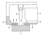
- In the following the invention is explained in more details with reference to the appended drawing which is a schematical view of one preferred embodiment of the invention applied to an optical emission analyser.
- According to the figure the sample 1 is pressed to the
probe 2 of an optical emission analyser so that between the sample 1 and theprobe 2 it is arranged a semi-labyrinth sealing 3 according to the invention. To the sealing 3 it is formed at least two labyrinth chambers 4 so that the choke point 4 between the labyrinth chambers 4 is in its width at least 50% about the width of the labyrinth chamber 4. In the figure, it is further described anelectrode 6 being in the measuring chamber, by means of that electrode it is formed an electric discharge between theelectrode 6 and the sample 1. The discharge evaporates some material off the sample surface and it is formed plasma, from which a distinctive spectrum for each element is conducted throught the slot 9 between thecollimator 7 and thewall 8 of the probe for further treatment. - The semi-labyrinth sealing according to the invention is advantageously manufactured of metal, as brass or stainless steel, but the semi-labyrinth sealing according to the invention can also be manufactured for example of an elastic material, as rubber, or of a ceramic material.
- The semi-labyrinth sealing according to the invention is advantageous between the sample and the measuring chamber of an optical emission analyser, but the sealing can also be used in analysers of other types in which between the stabile sample and the measuring chamber it is required a specially tight sealing. These kinds of analysers are for example portable x-ray analysers. Similarly, the analyser sealing created by a semi-labyrinth sealing according to the invention can be used in glow discharge lamps.
Claims (10)
Applications Claiming Priority (2)
| Application Number | Priority Date | Filing Date | Title |
|---|---|---|---|
| FI883013A FI81453C (en) | 1988-06-22 | 1988-06-22 | ANALYSATORTAETNING. |
| FI883013 | 1988-06-22 |
Publications (2)
| Publication Number | Publication Date |
|---|---|
| EP0348375A2 true EP0348375A2 (en) | 1989-12-27 |
| EP0348375A3 EP0348375A3 (en) | 1990-10-31 |
Family
ID=8526702
Family Applications (1)
| Application Number | Title | Priority Date | Filing Date |
|---|---|---|---|
| EP19890850211 Withdrawn EP0348375A3 (en) | 1988-06-22 | 1989-06-21 | Analyser sealing |
Country Status (5)
| Country | Link |
|---|---|
| US (1) | US5064204A (en) |
| EP (1) | EP0348375A3 (en) |
| CA (1) | CA1338036C (en) |
| FI (1) | FI81453C (en) |
| RU (1) | RU1830120C (en) |
Cited By (2)
| Publication number | Priority date | Publication date | Assignee | Title |
|---|---|---|---|---|
| EP0729174A3 (en) * | 1995-02-24 | 1997-01-15 | Leco Corp | Atmospheric seal and method for glow discharge analytical instrument |
| EP4300057A1 (en) * | 2022-07-01 | 2024-01-03 | Hitachi High-Tech Analytical Science GmbH | A spark stand assembly for an optical emission spectroscopy instrument |
Families Citing this family (7)
| Publication number | Priority date | Publication date | Assignee | Title |
|---|---|---|---|---|
| US5129623A (en) * | 1991-12-06 | 1992-07-14 | General Motors Corporation | Linear EGR tri-bearing |
| US6868566B2 (en) * | 2002-07-31 | 2005-03-22 | Michael Dean Gatten | Swaddling blanket |
| US20080308075A1 (en) * | 2007-06-13 | 2008-12-18 | Allen Christopher D | Automotive fuel system for substantially reducing hydrocarbon emissions into the atmosphere, and method |
| US20080308074A1 (en) * | 2007-06-13 | 2008-12-18 | Allen Christopher D | Evaporative emissions canister with external membrane |
| US20080308073A1 (en) * | 2007-06-13 | 2008-12-18 | Allen Christopher D | Evaporative emissions canister having an integral membrane |
| US20080308072A1 (en) * | 2007-06-13 | 2008-12-18 | Raja Banerjee | Hydrocarbon separation from air using membrane separators in recirculation tube |
| GB2592853B (en) | 2019-09-12 | 2022-04-13 | Thermo Fisher Scient Ecublens Sarl | A spark stand and method of maintenance |
Family Cites Families (18)
| Publication number | Priority date | Publication date | Assignee | Title |
|---|---|---|---|---|
| SU14308A1 (en) * | 1929-03-15 | 1930-03-31 | А.В. Бобров | Labyrinth springless oil seal for piston or spool rods of steam engines |
| US2878048A (en) * | 1954-03-18 | 1959-03-17 | Osborn Mfg Co | Brush seal and the like |
| US3013824A (en) * | 1958-04-07 | 1961-12-19 | Lockheed Aircraft Corp | Cable seal |
| DE2341204A1 (en) * | 1972-08-18 | 1974-02-28 | Commw Scient Ind Res Org | DEVICE FOR PERFORMING SPECTRAL ANALYSIS |
| GB1490991A (en) * | 1975-01-08 | 1977-11-09 | British Steel Corp | Determination of the constituents of metals |
| GB1574812A (en) * | 1976-05-06 | 1980-09-10 | Barringer Research Ltd | Spectrochemical analysis |
| DE2833324A1 (en) * | 1978-07-29 | 1980-02-14 | Schubert & Salzer Maschinen | Spark chamber for vacuum emission spectrometers - has sampling plate of thermally stable moulded laminated plastic |
| GB2042098B (en) * | 1979-02-17 | 1983-03-09 | Rolls Royce | Seals |
| US4401893A (en) * | 1981-07-29 | 1983-08-30 | Intec Corporation | Method and apparatus for optically inspecting a moving web of glass |
| DE3213660C2 (en) * | 1982-04-14 | 1985-09-19 | Klöckner-Werke AG, 4100 Duisburg | Probe for a portable spectrometer |
| DE3382460D1 (en) * | 1982-10-19 | 1991-12-19 | Varian Associates | MACHINING DEVICE WITH A DEVICE FOR GENERATING A LOCALIZED VACUUM. |
| US4484754A (en) * | 1984-01-31 | 1984-11-27 | Ballard Michael J | Ring seal with overlapping flanges for contaminant trapping |
| JPS60180056A (en) * | 1984-02-27 | 1985-09-13 | Shimadzu Corp | Glow discharge tube for emission spectrometry |
| SU1182224A1 (en) * | 1984-04-05 | 1985-09-30 | Предприятие П/Я Р-6977 | Shaft labyrinth packing |
| US4641968A (en) * | 1984-12-17 | 1987-02-10 | Baird Corporation | Mobile spectrometric apparatus |
| US4572517A (en) * | 1985-07-26 | 1986-02-25 | A. W. Chesterton Company | Labyrinth ring seals with housing mounting means |
| US4743034A (en) * | 1987-03-27 | 1988-05-10 | Durametallic Corporation | Labyrinth bearing protector seal |
| US4842287A (en) * | 1987-10-22 | 1989-06-27 | Helix Technology Corporation | Helium pressure seal for a cryogenic refrigerator |
-
1988
- 1988-06-22 FI FI883013A patent/FI81453C/en not_active IP Right Cessation
-
1989
- 1989-06-21 EP EP19890850211 patent/EP0348375A3/en not_active Withdrawn
- 1989-06-21 RU SU894614516A patent/RU1830120C/en active
- 1989-06-21 CA CA000603480A patent/CA1338036C/en not_active Expired - Lifetime
-
1991
- 1991-01-22 US US07/644,403 patent/US5064204A/en not_active Expired - Lifetime
Cited By (4)
| Publication number | Priority date | Publication date | Assignee | Title |
|---|---|---|---|---|
| EP0729174A3 (en) * | 1995-02-24 | 1997-01-15 | Leco Corp | Atmospheric seal and method for glow discharge analytical instrument |
| US5646726A (en) * | 1995-02-24 | 1997-07-08 | Leco Corporation | Atmospheric seal for glow discharge analytical instrument |
| EP4300057A1 (en) * | 2022-07-01 | 2024-01-03 | Hitachi High-Tech Analytical Science GmbH | A spark stand assembly for an optical emission spectroscopy instrument |
| US12392725B2 (en) | 2022-07-01 | 2025-08-19 | Hitachi High-Tech Analytical Science GmbH | Spark stand assembly for an optical emission spectroscopy instrument |
Also Published As
| Publication number | Publication date |
|---|---|
| FI81453C (en) | 1990-10-10 |
| RU1830120C (en) | 1993-07-23 |
| US5064204A (en) | 1991-11-12 |
| CA1338036C (en) | 1996-02-06 |
| FI883013L (en) | 1989-12-23 |
| FI81453B (en) | 1990-06-29 |
| EP0348375A3 (en) | 1990-10-31 |
| FI883013A0 (en) | 1988-06-22 |
Similar Documents
| Publication | Publication Date | Title |
|---|---|---|
| US6254749B1 (en) | Carbon monoxide gas sensor and measuring device using the same sensor | |
| EP0348375A2 (en) | Analyser sealing | |
| EP0030164B1 (en) | An oxygen concentration detector and a method of detecting oxygen concentration | |
| EP0805973A4 (en) | ||
| EP2264447A3 (en) | Apparatus for Generating a High Purity Eluant | |
| EP0718247A4 (en) | Lithium ion-conductive glass film and thin carbon dioxide gas sensor using the same film | |
| JPH07225214A (en) | NOx measuring device | |
| KR860009604A (en) | Plasma processing equipment | |
| US5014009A (en) | Detector for gas chromatograph for detecting ammonia and amine compounds | |
| KR890013967A (en) | Plasma processing apparatus and plasma temperature measuring method | |
| EP0772043A3 (en) | Fluorelastomer gasket for blood analyte sensors | |
| Maclay et al. | Microfabricated amperometric gas sensors | |
| US3882011A (en) | Electrode for electroanalytic studies | |
| JPS57192855A (en) | Oxygen concentration detector | |
| JPS59170758A (en) | Method and device for measuring concentration of oxygen in gas mixture | |
| US4592825A (en) | Probe for measuring oxygen partial pressure in a gas atmosphere | |
| JPS559178A (en) | Oxygen concentration detector | |
| AU608717B2 (en) | Graphite tube furnace with specimen support for atomic absorption spectroscopy | |
| EP0249267A3 (en) | Electrochemical sensor for the measurement of corrosion in metal equipment | |
| EP0362736A3 (en) | Oxygen probe for a heat treatment oven | |
| JPH0798308A (en) | Combustion elemental analyzer | |
| McCleary et al. | Evaluation of a demountable tangential flow torch for microwave-induced plasma atomic emission spectrometry | |
| SU1396029A1 (en) | Method of analyzing hydrogen concentration in air | |
| Hazelby | A versatile gas analysis apparatus incorporating a small mass spectrometer | |
| SE8604993D0 (en) | INSTRUCTION FOR EXAMINATION PHYSICAL-CHEMICAL KNOWLEDGE OF METAL, SPECIAL STEEL MELZING |
Legal Events
| Date | Code | Title | Description |
|---|---|---|---|
| PUAI | Public reference made under article 153(3) epc to a published international application that has entered the european phase |
Free format text: ORIGINAL CODE: 0009012 |
|
| AK | Designated contracting states |
Kind code of ref document: A2 Designated state(s): AT DE FR GB IT NL SE |
|
| PUAL | Search report despatched |
Free format text: ORIGINAL CODE: 0009013 |
|
| AK | Designated contracting states |
Kind code of ref document: A3 Designated state(s): AT DE FR GB IT NL SE |
|
| 17P | Request for examination filed |
Effective date: 19901115 |
|
| 17Q | First examination report despatched |
Effective date: 19920401 |
|
| STAA | Information on the status of an ep patent application or granted ep patent |
Free format text: STATUS: THE APPLICATION IS DEEMED TO BE WITHDRAWN |
|
| 18D | Application deemed to be withdrawn |
Effective date: 19921013 |