EP0348313B2 - Gekapselte Station für Hochspannung mit Zweifachversorgung - Google Patents
Gekapselte Station für Hochspannung mit Zweifachversorgung Download PDFInfo
- Publication number
- EP0348313B2 EP0348313B2 EP19890420218 EP89420218A EP0348313B2 EP 0348313 B2 EP0348313 B2 EP 0348313B2 EP 19890420218 EP19890420218 EP 19890420218 EP 89420218 A EP89420218 A EP 89420218A EP 0348313 B2 EP0348313 B2 EP 0348313B2
- Authority
- EP
- European Patent Office
- Prior art keywords
- circuit breaker
- busbar
- compartment
- intermediate conductor
- switching
- Prior art date
- Legal status (The legal status is an assumption and is not a legal conclusion. Google has not performed a legal analysis and makes no representation as to the accuracy of the status listed.)
- Expired - Lifetime
Links
- 239000004020 conductor Substances 0.000 claims description 24
- 230000008439 repair process Effects 0.000 claims description 12
- 239000002184 metal Substances 0.000 claims description 6
- 239000012212 insulator Substances 0.000 description 11
- 238000002955 isolation Methods 0.000 description 9
- 241000722921 Tulipa gesneriana Species 0.000 description 6
- 229910018503 SF6 Inorganic materials 0.000 description 5
- SFZCNBIFKDRMGX-UHFFFAOYSA-N sulfur hexafluoride Chemical compound FS(F)(F)(F)(F)F SFZCNBIFKDRMGX-UHFFFAOYSA-N 0.000 description 5
- 238000005259 measurement Methods 0.000 description 3
- 230000015572 biosynthetic process Effects 0.000 description 2
- 238000009434 installation Methods 0.000 description 2
- 238000005192 partition Methods 0.000 description 2
- 238000000638 solvent extraction Methods 0.000 description 2
- 230000000712 assembly Effects 0.000 description 1
- 238000000429 assembly Methods 0.000 description 1
- 238000005520 cutting process Methods 0.000 description 1
- 230000002950 deficient Effects 0.000 description 1
- 238000010586 diagram Methods 0.000 description 1
- 238000009826 distribution Methods 0.000 description 1
- 238000004519 manufacturing process Methods 0.000 description 1
- 238000000034 method Methods 0.000 description 1
- 238000012544 monitoring process Methods 0.000 description 1
- 238000012552 review Methods 0.000 description 1
- 238000007789 sealing Methods 0.000 description 1
- 229960000909 sulfur hexafluoride Drugs 0.000 description 1
- 238000013022 venting Methods 0.000 description 1
Images


Classifications
-
- H—ELECTRICITY
- H02—GENERATION; CONVERSION OR DISTRIBUTION OF ELECTRIC POWER
- H02B—BOARDS, SUBSTATIONS OR SWITCHING ARRANGEMENTS FOR THE SUPPLY OR DISTRIBUTION OF ELECTRIC POWER
- H02B1/00—Frameworks, boards, panels, desks, casings; Details of substations or switching arrangements
- H02B1/20—Bus-bar or other wiring layouts, e.g. in cubicles, in switchyards
- H02B1/22—Layouts for duplicate bus-bar selection
-
- H—ELECTRICITY
- H02—GENERATION; CONVERSION OR DISTRIBUTION OF ELECTRIC POWER
- H02B—BOARDS, SUBSTATIONS OR SWITCHING ARRANGEMENTS FOR THE SUPPLY OR DISTRIBUTION OF ELECTRIC POWER
- H02B13/00—Arrangement of switchgear in which switches are enclosed in, or structurally associated with, a casing, e.g. cubicle
- H02B13/02—Arrangement of switchgear in which switches are enclosed in, or structurally associated with, a casing, e.g. cubicle with metal casing
- H02B13/035—Gas-insulated switchgear
- H02B13/0352—Gas-insulated switchgear for three phase switchgear
-
- H—ELECTRICITY
- H02—GENERATION; CONVERSION OR DISTRIBUTION OF ELECTRIC POWER
- H02B—BOARDS, SUBSTATIONS OR SWITCHING ARRANGEMENTS FOR THE SUPPLY OR DISTRIBUTION OF ELECTRIC POWER
- H02B5/00—Non-enclosed substations; Substations with enclosed and non-enclosed equipment
- H02B5/06—Non-enclosed substations; Substations with enclosed and non-enclosed equipment gas-insulated
Definitions
- the busbar being repaired can be isolated from the bay by opening the switch disconnector contacts while maintaining the pressure of the insulating gas SF6 in the intermediate casing.
- Such an architecture is expensive because it requires sealing along the passages for the disconnector pins, and a device for monitoring the gas pressure in each casing of the sectioning area of the switch disconnectors.
- the object of the invention is to simplify the production of an armored substation with double power busbars, allowing intervention on one of the busbars without simultaneously switching off two adjacent spans.
- the shielded post according to the invention is characterized in that the disconnectable electrical connection is arranged axially at each end of the intermediate conductor to create, after dismantling, a first or a second isolation interval A, B predetermined in the circuit breaker compartment, respectively with the connection connectors of one of the switch disconnectors, the circuit breaker being supplied via the other switch disconnector, that one end of the intermediate conductor has a first tulip contact intended to receive a first contact pad secured to a splice-shaped connection piece, fixed by a first assembly screw to the connector of the first switch disconnector, the dismantling of the splice after unscrewing the screw generating said first isolation interval A in case of repair of the first set of bar, and that the other end of the intermediate conductor is equipped with a second contact pad intended to penetrate into a second tulip contact carried by the connector of the second switch disconnector, the disassembly of the second contact pad generating said second isolation interval B in the event of repair of the second busbar.
- the invention is applicable to a single-phase or three-phase envelope station.
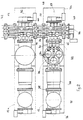
- an armored high-voltage distribution station includes a grounded metal casing 10 filled with a gas with high dielectric strength, in particular sulfur hexafluoride under pressure.
- the substation is equipped with a plurality of spans 12, 12a, (two are shown in FIG. 2), staggered at regular intervals along a first and a second set of supply busbars 14, 16, each bay 12,12a containing the specific electrical equipment for interruption, sectioning and connection associated with a departure 18.
- Each set of bars 14, 16 is housed in a cylindrical enclosure 19 forming part of the metal casing 10, and comprises three bars 20, 22, 24; 26,28,30 conductors of three-phase supply.
- the two busbars 14,16 are superimposed in the height direction, and the spans 12,12a are on the same side of the enclosure 19.
- each bay 12, 12a is subdivided into different compartments formed by elementary sections or boxes connected to each other in a leaktight manner by flanges or connection end pieces, with the interposition of support insulators 32 forming the partitioning between the adjacent compartments.
- the support insulators 32 are crossed by the bars and the electrical conductors for the electrical connection of the elements of the apparatus contained in the compartments.
- Each bay 12, 12a comprises a three-pole circuit breaker 34 housed in a circuit breaker compartment 36 having three connection ends, respectively to a measurement compartment 38 on the left side, and to two busbar compartments 40, 42 superimposed on the right side.
- the measurement compartment 38 contains a three-phase current transformer 44 and a three-phase earthing switch 46.
- the upper busbar compartment 40 associated with the first set of bars 14 contains, in addition to the three conductive bars 20, 22, 24 of electrical supply, a first three-phase switch disconnector 45 intended to ensure the electrical connection of the circuit breaker 34 to the corresponding bars. 20,22,24 in the closed position, and the electrical isolation in the open position.
- the switch disconnector 45 is actuated by sliding by a control mechanism 48 fixed to the external flange of the compartment 40, while the opposite flange for connection to the circuit breaker compartment 36 carries the fixed contacts of the switch disconnector 45 including the movable pins (not shown) actuated by the insulating rods 49 extend perpendicular to the feed bars 20,22,24.
- the composition of the lower busbar compartment 42 is identical to that of the upper compartment 40, and is equipped with a second three-phase switch disconnector 47 (see FIG. 3) associated with the second busbar 16, and controlled by a command 50 (figure 1).
- the measurement compartment 38 is interposed between the circuit breaker compartment 36 and a sectioning compartment 52 containing a three-phase line disconnector 54 actuated by a control mechanism 56.
- the outgoing cables 18 are connected to a connection compartment 58 containing a box three-phase cables 60 and a three-phase earthing switch 62 controlled by a control mechanism 64.
- the connection compartment 58 is placed under the sectioning compartment 52, and is supported on the base 64 by means of a support mechanical 66 fixed.
- the base 64 On the intermediate part of the base 64 also rests the box 67 for controlling the circuit breaker 34.
- the poles of the latter extend vertically inside the circuit breaker compartment 36, which also contains a three-phase earthing switch 68.
- the electrical connection device 70 common between the three-pole circuit breaker 34 and the two switch disconnectors 45, 47 associated with the two busbars 14, 16, is housed in the circuit breaker compartment 36, extending parallel to the poles of the circuit breaker 34.
- the lower part of the connection device 70 is equipped with three fixed contacts 72 cooperating with the corresponding movable pins of the three-phase earthing switch 68.
- a three-phase earthing switch 74,76 (see FIGS. 2 and 3) is associated on the other hand with each busbar 14,16 to ensure the earthing of the corresponding bars 20,22,24; 26,28,30.
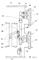
- connection device 70 between the circuit breaker 34 and the two busbars 14, 16 comprises according to the invention (see FIGS. 4 and 5), a first series of three connectors 80 fixed to the respective poles of the circuit breaker 34, a second series of three connectors 82 carried by the support insulator 32 of the upper busbar compartment 40, and a third series of three connectors 84 carried by the support insulator 32 of the lower busbar compartment 42.
- the fixed contacts 72 of the earthing switch 68 are arranged at the bottom of the connectors 84, which, on the other hand, have tulip contacts 85 intended to receive studs e contact 86 secured to intermediate conductors 88 constituting a common electrical connection of the circuit breaker 34 with the two busbars 14,16.
- the conductors 88 are fitted with tulip contacts 90 cooperating by plugging in with contact pads 92 secured to splice-shaped connecting pieces 94, fixed to the corresponding connectors 82 by screws assembly 96.
- the intermediate part of each connecting conductor 88 is provided with a strip 98 for connection with the corresponding connector 80 of the circuit breaker 38. The connection is made by assembly screws 99.
- FIG. 5 shows the interior of the circuit breaker compartment 36 after complete removal of the connection device 70.
- connection method (see Figures 6 and 7) of the connection device 70 depends on the busbar 14 or 16 damaged or being repaired.
- the invention has been described as being applied to a three-phase station with a common housing for the three phases, but it naturally extends to stations with separate phases, each phase having its own earthed metal casing.
Landscapes
- Engineering & Computer Science (AREA)
- Power Engineering (AREA)
- Gas-Insulated Switchgears (AREA)
Claims (2)
- Gekapselte Hochspannungs-Schaltanlage mit doppelter Sammelschieneneinspeisung (14, 16) in einem geerdeten und mit einem Isoliergas hoher dielektrischer Festigkeit gefüllten Metallgehäuse (10), das pro Schaltfeld (12, 12a) in mehrere gasdichte Abteile, insbesondere mit folgender Bestückung, unterteilt ist:- ein Leistungsschalterabteil (36) mit einem Leistungsschalter (34) zum Schutz des Abgangs (18) des jeweiligen Schaltfelds (12, 12a);- ein erstes Sammelschienenabteil (40) mit einem ersten Sammelschienen-Umschalttrenner (45), der mit mindestens einer Sammelschiene (20, 22, 24) der ersten Einspeisung (14) verbunden ist,- ein zweites Sammelschienenabteil (42) mit einem zweiten Sammelschienen-Umschalttrenner (47), der mit mindestens einer Sammelschiene (20, 22, 24) der zweiten Einspeisung (14) verbunden ist,- und ein zwischen dem Leistungsschalter (34) und den beiden Sammelschienen-Umschalttrennern (45, 47) angeordnetes gemeinsames Verbindungsstück (70), welches im Leistungsschalterabteil (36) angeordnet ist und ein Zwischenleiterelement (88), das parallel zum Leistungsschalter (34) sowie in einer Flucht mit einem Erdungsschalter (68) verläuft und den gemeinsamen Anschlußpunkt des Leistungsschalters (34) und der beiden Einspeisungen (14, 16) darstellt, sowie mindestens eine trennbare elektrische Verbindung (94, 92, 86) umfaßt,dadurch gekennzeichnet daß
daß die trennbare elektrische Verbindung (94, 92, 86) an den beiden Enden des Zwischenleiterelements (88) ausgebildet ist, um nach ihrer Unterbrechung im Leistungsschalterabteil (36) eine festgelegte erste bzw. zweite Trennstrecke A, B in bezug auf die Anschlußklemmen (82, 84) eines der Sammelschienen-Umschalttrenner (45, 47) zu schaffen, wobei der jeweils andere Sammelschienen-Umschalttrenner die Einspeisung des Leistungsschalters (34) übernimmt, daß ein Anschlußende des Zwischenleiterelements (88) eine erste Kontaktzange (90) zur Aufnahme eines ersten Kontaktstifts (92) aufweist, der mit einem, über eine Verbindungsschraube (96) an der Anschlußklemme (82) des ersten Sammelschienen-Umschalttrenners (45) befestigten, laschenförmigen Anschlußstück (94) fest verbunden ist, wobei durch Lösen der Anschlußlasche (94) nach Herausdrehen der Schraube (96) die genannte erste Trennstrecke A für die Instandsetzung der ersten Einspeisung (14) entsteht, und daß das andere Anschlußende des Zwischenleiterelements (88) einen zweiten Kontaktstift (86) zur Einführung in eine zweite Kontaktzange (85) aufweist, die an der Anschlußklemme (84) des zweiten Sammelschienen-Umschalttrenners (47) befestigt ist, wobei durch die Trennung des zweiten Kontaktstifts (86) die genannte zweite Trennstrecke B für die Instandsetzung der zweiten Einspeisung (16) entsteht. - Gekapselte Schaltanlage nach Anspruch 1, dadurch gekennzeichnet, daß an der gegenüberliegenden Seite der zweiten Kontaktzange (85) der Anschlußklemme (84) eine dritte, feststehende Kontaktzange (72) angeordnet ist, die mit dem beweglichen Kontakt des Erdungsschalters (68) zusammenwirkt, und daß das Zwischenleiterelement (88) einen, über eine zweite Befestigungsschraube (99) mit dem Leistungsschalter (34) verbundenen Anschlußsteg (98) aufweist, wobei die erste und die zweite Schraube (96, 99) nach dem Entfernen des an der Oberseite des Leistungsschalterabteils (36) angebrachten Deckels (97) zugänglich sind.
Applications Claiming Priority (2)
| Application Number | Priority Date | Filing Date | Title |
|---|---|---|---|
| FR8808353A FR2633109B1 (fr) | 1988-06-20 | 1988-06-20 | Poste blinde a haute tension et a double jeu de barres d'alimentation |
| FR8808353 | 1988-06-20 |
Publications (3)
| Publication Number | Publication Date |
|---|---|
| EP0348313A1 EP0348313A1 (de) | 1989-12-27 |
| EP0348313B1 EP0348313B1 (de) | 1993-01-13 |
| EP0348313B2 true EP0348313B2 (de) | 1997-03-26 |
Family
ID=9367563
Family Applications (1)
| Application Number | Title | Priority Date | Filing Date |
|---|---|---|---|
| EP19890420218 Expired - Lifetime EP0348313B2 (de) | 1988-06-20 | 1989-06-14 | Gekapselte Station für Hochspannung mit Zweifachversorgung |
Country Status (5)
| Country | Link |
|---|---|
| EP (1) | EP0348313B2 (de) |
| JP (1) | JP2590264B2 (de) |
| BR (1) | BR8902953A (de) |
| DE (1) | DE68904362T3 (de) |
| FR (1) | FR2633109B1 (de) |
Families Citing this family (9)
| Publication number | Priority date | Publication date | Assignee | Title |
|---|---|---|---|---|
| DE4210370A1 (de) * | 1992-03-30 | 1993-10-07 | Abb Patent Gmbh | Hochspannungsschaltfeld |
| DE4210368A1 (de) * | 1992-03-30 | 1993-10-07 | Abb Patent Gmbh | Hochspannungsschaltfeld |
| JP3175434B2 (ja) | 1993-10-21 | 2001-06-11 | 株式会社日立製作所 | ガス絶縁開閉装置 |
| DE9316832U1 (de) * | 1993-10-29 | 1994-03-24 | Siemens AG, 80333 München | Leiterverbindung |
| DE4438776C1 (de) * | 1994-10-21 | 1996-04-11 | Siemens Ag | Metallgekapselte elektrische Hochspannungsschaltanlage mit einem Leistungsschalter |
| ES2264319A1 (es) * | 2004-04-16 | 2006-12-16 | Ormazabal Distribucion Primaria, S.A. | Aparamenta modular de alta tension. |
| CN104410002B (zh) * | 2014-12-05 | 2017-09-08 | 北京合锐赛尔电力科技股份有限公司 | 一种智能固体绝缘环网柜 |
| DE102019209875A1 (de) * | 2019-07-04 | 2021-01-07 | Siemens Aktiengesellschaft | Schalteinrichtung |
| CN116054003A (zh) * | 2022-11-08 | 2023-05-02 | 西安西电开关电气有限公司 | 集成开关设备 |
Family Cites Families (2)
| Publication number | Priority date | Publication date | Assignee | Title |
|---|---|---|---|---|
| DE1681782U (de) * | 1954-02-19 | 1954-08-19 | Licentia Gmbh | Blechgekapselter schaltschrank fuer hoch- oder niederspannungsanlagen. |
| FR2594607B1 (fr) * | 1986-02-14 | 1988-04-29 | Merlin Gerin | Poste blinde subdivise en compartiments etanches |
-
1988
- 1988-06-20 FR FR8808353A patent/FR2633109B1/fr not_active Expired - Fee Related
-
1989
- 1989-06-14 JP JP1152070A patent/JP2590264B2/ja not_active Expired - Lifetime
- 1989-06-14 EP EP19890420218 patent/EP0348313B2/de not_active Expired - Lifetime
- 1989-06-14 DE DE68904362T patent/DE68904362T3/de not_active Expired - Fee Related
- 1989-06-19 BR BR8902953A patent/BR8902953A/pt not_active IP Right Cessation
Also Published As
| Publication number | Publication date |
|---|---|
| EP0348313B1 (de) | 1993-01-13 |
| EP0348313A1 (de) | 1989-12-27 |
| FR2633109B1 (fr) | 1990-09-21 |
| FR2633109A1 (fr) | 1989-12-22 |
| DE68904362T3 (de) | 1997-07-17 |
| JPH02237405A (ja) | 1990-09-20 |
| DE68904362D1 (de) | 1993-02-25 |
| DE68904362T2 (de) | 1993-08-12 |
| JP2590264B2 (ja) | 1997-03-12 |
| BR8902953A (pt) | 1990-02-06 |
Similar Documents
| Publication | Publication Date | Title |
|---|---|---|
| EP0543683B1 (de) | Mittelspannungs-Lasttrennschalter und Verwendung in einer Mittelspannungszelle und Mittelspannungspost | |
| US3983460A (en) | Enclosed circuit interrupter with improved fuse assembly | |
| CA2147085A1 (en) | Metal-enclosed gas-filled switchgear units | |
| EP0348313B2 (de) | Gekapselte Station für Hochspannung mit Zweifachversorgung | |
| EP0235006B1 (de) | Metallgekapselte Schaltanlage mit gasdichten Teilabschnitten | |
| EP1329008B2 (de) | Hybrid-hochspannungsstation mit gegenüberliegenden abgangen, und gekapselten schalt- undtrennmodulen dafür | |
| EP0165184B1 (de) | Metallverkapselte gasisolierte dreiphasige Schaltanlage | |
| FR2646568A1 (en) | Electrical distribution panel equipped with isolators | |
| FR2555830A1 (fr) | Poste blinde a isolation a gaz sous pression | |
| DE3820489A1 (de) | Gekapselte lasttrennschalteranordnung | |
| EP0338382B1 (de) | Zelle für gekapselte Mittel oder Hochspannungsstation und Station, die aus solchen Zellen aufgebaut ist | |
| EP0030489B1 (de) | In der Fabrik vorgefertigte elektrische Mittelspannungsschaltanlage und Verfahren zu ihrer Montage | |
| EP0348312B1 (de) | Gekapselte Station für ein Hochspannungsnetz | |
| US9780539B2 (en) | Method of extracting a jacket of a gas insulated substation (GIS) under a metal casing | |
| EP1079489A1 (de) | Schaltanlage mit Doppelsammelschienen und zugehörige Schalt- und Trennvorrichtung | |
| JP3541657B2 (ja) | ガス絶縁開閉装置及びその分岐回線ユニットの交換方法 | |
| FR2558013A1 (fr) | Armoire de raccordement en derivation d'un poste electrique moyenne tension | |
| FR2629283A1 (fr) | Travee d'un poste blinde haute tension | |
| EP0002398A1 (de) | Verbesserungen an Stromverteilungszellen | |
| JPH0620329B2 (ja) | ガス絶縁開閉装置 | |
| CN105305288A (zh) | 具有分成封闭间隔的金属铠装配电装置 | |
| JPH0620334B2 (ja) | ガス絶縁開閉装置 | |
| FR2471064A1 (fr) | Cellule electrique a disjoncteur sectionnable | |
| JPH10336819A (ja) | ガス絶縁開閉装置 | |
| FR2649256A1 (en) | Screened electrical installation having a set of bars including contractable sections |
Legal Events
| Date | Code | Title | Description |
|---|---|---|---|
| PUAI | Public reference made under article 153(3) epc to a published international application that has entered the european phase |
Free format text: ORIGINAL CODE: 0009012 |
|
| AK | Designated contracting states |
Kind code of ref document: A1 Designated state(s): CH DE IT LI SE |
|
| 17P | Request for examination filed |
Effective date: 19900525 |
|
| 17Q | First examination report despatched |
Effective date: 19920327 |
|
| GRAA | (expected) grant |
Free format text: ORIGINAL CODE: 0009210 |
|
| AK | Designated contracting states |
Kind code of ref document: B1 Designated state(s): CH DE IT LI SE |
|
| RIN1 | Information on inventor provided before grant (corrected) |
Inventor name: DIAFERIA, ALDO Inventor name: MESSIE, MICHEL |
|
| REF | Corresponds to: |
Ref document number: 68904362 Country of ref document: DE Date of ref document: 19930225 |
|
| ITF | It: translation for a ep patent filed | ||
| PLBI | Opposition filed |
Free format text: ORIGINAL CODE: 0009260 |
|
| 26 | Opposition filed |
Opponent name: SIEMENS AG Effective date: 19930928 |
|
| EAL | Se: european patent in force in sweden |
Ref document number: 89420218.3 |
|
| PLAW | Interlocutory decision in opposition |
Free format text: ORIGINAL CODE: EPIDOS IDOP |
|
| PLAW | Interlocutory decision in opposition |
Free format text: ORIGINAL CODE: EPIDOS IDOP |
|
| PUAH | Patent maintained in amended form |
Free format text: ORIGINAL CODE: 0009272 |
|
| STAA | Information on the status of an ep patent application or granted ep patent |
Free format text: STATUS: PATENT MAINTAINED AS AMENDED |
|
| 27A | Patent maintained in amended form |
Effective date: 19970326 |
|
| AK | Designated contracting states |
Kind code of ref document: B2 Designated state(s): CH DE IT LI SE |
|
| REG | Reference to a national code |
Ref country code: CH Ref legal event code: AEN Free format text: MAINTIEN DU BREVET DONT L'ETENDUE A ETE MODIFIEE |
|
| ITF | It: translation for a ep patent filed | ||
| PGFP | Annual fee paid to national office [announced via postgrant information from national office to epo] |
Ref country code: SE Payment date: 20000606 Year of fee payment: 12 |
|
| PGFP | Annual fee paid to national office [announced via postgrant information from national office to epo] |
Ref country code: CH Payment date: 20000613 Year of fee payment: 12 |
|
| PGFP | Annual fee paid to national office [announced via postgrant information from national office to epo] |
Ref country code: DE Payment date: 20010609 Year of fee payment: 13 |
|
| PG25 | Lapsed in a contracting state [announced via postgrant information from national office to epo] |
Ref country code: SE Free format text: LAPSE BECAUSE OF NON-PAYMENT OF DUE FEES Effective date: 20010615 |
|
| PG25 | Lapsed in a contracting state [announced via postgrant information from national office to epo] |
Ref country code: LI Free format text: LAPSE BECAUSE OF NON-PAYMENT OF DUE FEES Effective date: 20010630 Ref country code: CH Free format text: LAPSE BECAUSE OF NON-PAYMENT OF DUE FEES Effective date: 20010630 |
|
| EUG | Se: european patent has lapsed |
Ref document number: 89420218.3 |
|
| REG | Reference to a national code |
Ref country code: CH Ref legal event code: PL |
|
| PG25 | Lapsed in a contracting state [announced via postgrant information from national office to epo] |
Ref country code: DE Free format text: LAPSE BECAUSE OF NON-PAYMENT OF DUE FEES Effective date: 20030101 |
|
| PG25 | Lapsed in a contracting state [announced via postgrant information from national office to epo] |
Ref country code: IT Free format text: LAPSE BECAUSE OF NON-PAYMENT OF DUE FEES;WARNING: LAPSES OF ITALIAN PATENTS WITH EFFECTIVE DATE BEFORE 2007 MAY HAVE OCCURRED AT ANY TIME BEFORE 2007. THE CORRECT EFFECTIVE DATE MAY BE DIFFERENT FROM THE ONE RECORDED. Effective date: 20050614 |