EP0348227B1 - Side wall construction for continuous belt caster - Google Patents
Side wall construction for continuous belt caster Download PDFInfo
- Publication number
- EP0348227B1 EP0348227B1 EP89306400A EP89306400A EP0348227B1 EP 0348227 B1 EP0348227 B1 EP 0348227B1 EP 89306400 A EP89306400 A EP 89306400A EP 89306400 A EP89306400 A EP 89306400A EP 0348227 B1 EP0348227 B1 EP 0348227B1
- Authority
- EP
- European Patent Office
- Prior art keywords
- side wall
- refractory layer
- chamber
- layer
- wear
- Prior art date
- Legal status (The legal status is an assumption and is not a legal conclusion. Google has not performed a legal analysis and makes no representation as to the accuracy of the status listed.)
- Expired - Lifetime
Links
- 238000010276 construction Methods 0.000 title description 9
- 238000005266 casting Methods 0.000 claims description 32
- 239000000463 material Substances 0.000 claims description 23
- VYPSYNLAJGMNEJ-UHFFFAOYSA-N Silicium dioxide Chemical compound O=[Si]=O VYPSYNLAJGMNEJ-UHFFFAOYSA-N 0.000 claims description 22
- 229910052751 metal Inorganic materials 0.000 claims description 16
- 239000002184 metal Substances 0.000 claims description 16
- 239000000377 silicon dioxide Substances 0.000 claims description 11
- 239000010425 asbestos Substances 0.000 claims description 9
- 229910052895 riebeckite Inorganic materials 0.000 claims description 9
- 239000004744 fabric Substances 0.000 claims description 6
- 239000011449 brick Substances 0.000 claims description 5
- 229910052681 coesite Inorganic materials 0.000 claims description 5
- 229910052906 cristobalite Inorganic materials 0.000 claims description 5
- 235000012239 silicon dioxide Nutrition 0.000 claims description 5
- 229910052682 stishovite Inorganic materials 0.000 claims description 5
- 229910052905 tridymite Inorganic materials 0.000 claims description 5
- 229910052582 BN Inorganic materials 0.000 claims description 4
- PZNSFCLAULLKQX-UHFFFAOYSA-N Boron nitride Chemical compound N#B PZNSFCLAULLKQX-UHFFFAOYSA-N 0.000 claims description 4
- 229910052581 Si3N4 Inorganic materials 0.000 claims description 3
- QCWXUUIWCKQGHC-UHFFFAOYSA-N Zirconium Chemical compound [Zr] QCWXUUIWCKQGHC-UHFFFAOYSA-N 0.000 claims description 3
- PNEYBMLMFCGWSK-UHFFFAOYSA-N aluminium oxide Inorganic materials [O-2].[O-2].[O-2].[Al+3].[Al+3] PNEYBMLMFCGWSK-UHFFFAOYSA-N 0.000 claims description 3
- KZHJGOXRZJKJNY-UHFFFAOYSA-N dioxosilane;oxo(oxoalumanyloxy)alumane Chemical compound O=[Si]=O.O=[Si]=O.O=[Al]O[Al]=O.O=[Al]O[Al]=O.O=[Al]O[Al]=O KZHJGOXRZJKJNY-UHFFFAOYSA-N 0.000 claims description 3
- 239000003365 glass fiber Substances 0.000 claims description 3
- 230000005499 meniscus Effects 0.000 claims description 3
- 229910052863 mullite Inorganic materials 0.000 claims description 3
- -1 sialon Inorganic materials 0.000 claims description 3
- HQVNEWCFYHHQES-UHFFFAOYSA-N silicon nitride Chemical compound N12[Si]34N5[Si]62N3[Si]51N64 HQVNEWCFYHHQES-UHFFFAOYSA-N 0.000 claims description 3
- 229910052726 zirconium Inorganic materials 0.000 claims description 3
- 230000003467 diminishing effect Effects 0.000 claims description 2
- 239000011490 mineral wool Substances 0.000 claims description 2
- 239000010410 layer Substances 0.000 description 72
- 239000000155 melt Substances 0.000 description 14
- 239000002826 coolant Substances 0.000 description 7
- 238000009749 continuous casting Methods 0.000 description 4
- 238000001816 cooling Methods 0.000 description 4
- 238000002474 experimental method Methods 0.000 description 4
- 239000011819 refractory material Substances 0.000 description 4
- 229910000655 Killed steel Inorganic materials 0.000 description 3
- 229910000831 Steel Inorganic materials 0.000 description 3
- 230000000052 comparative effect Effects 0.000 description 3
- 238000002844 melting Methods 0.000 description 3
- 230000008018 melting Effects 0.000 description 3
- 238000000034 method Methods 0.000 description 3
- 238000007711 solidification Methods 0.000 description 3
- 230000008023 solidification Effects 0.000 description 3
- 239000010959 steel Substances 0.000 description 3
- OKTJSMMVPCPJKN-UHFFFAOYSA-N Carbon Chemical compound [C] OKTJSMMVPCPJKN-UHFFFAOYSA-N 0.000 description 2
- 229910000805 Pig iron Inorganic materials 0.000 description 2
- 239000004411 aluminium Substances 0.000 description 2
- 229910052782 aluminium Inorganic materials 0.000 description 2
- XAGFODPZIPBFFR-UHFFFAOYSA-N aluminium Chemical compound [Al] XAGFODPZIPBFFR-UHFFFAOYSA-N 0.000 description 2
- 230000015572 biosynthetic process Effects 0.000 description 2
- 229910052799 carbon Inorganic materials 0.000 description 2
- 239000000498 cooling water Substances 0.000 description 2
- 230000003247 decreasing effect Effects 0.000 description 2
- 230000007547 defect Effects 0.000 description 2
- 230000000694 effects Effects 0.000 description 2
- 238000010438 heat treatment Methods 0.000 description 2
- 239000000203 mixture Substances 0.000 description 2
- 230000035515 penetration Effects 0.000 description 2
- 230000035939 shock Effects 0.000 description 2
- 239000002356 single layer Substances 0.000 description 2
- 210000002268 wool Anatomy 0.000 description 2
- 241001391944 Commicarpus scandens Species 0.000 description 1
- RQMIWLMVTCKXAQ-UHFFFAOYSA-N [AlH3].[C] Chemical compound [AlH3].[C] RQMIWLMVTCKXAQ-UHFFFAOYSA-N 0.000 description 1
- 238000010521 absorption reaction Methods 0.000 description 1
- 238000005452 bending Methods 0.000 description 1
- 230000006835 compression Effects 0.000 description 1
- 238000007906 compression Methods 0.000 description 1
- 239000012809 cooling fluid Substances 0.000 description 1
- 239000005068 cooling lubricant Substances 0.000 description 1
- 230000007423 decrease Effects 0.000 description 1
- 238000009413 insulation Methods 0.000 description 1
- 238000002955 isolation Methods 0.000 description 1
- 238000012986 modification Methods 0.000 description 1
- 230000004048 modification Effects 0.000 description 1
- 239000011435 rock Substances 0.000 description 1
- 239000002893 slag Substances 0.000 description 1
- 238000004901 spalling Methods 0.000 description 1
- 230000001360 synchronised effect Effects 0.000 description 1
Images



Classifications
-
- B—PERFORMING OPERATIONS; TRANSPORTING
- B22—CASTING; POWDER METALLURGY
- B22D—CASTING OF METALS; CASTING OF OTHER SUBSTANCES BY THE SAME PROCESSES OR DEVICES
- B22D11/00—Continuous casting of metals, i.e. casting in indefinite lengths
- B22D11/06—Continuous casting of metals, i.e. casting in indefinite lengths into moulds with travelling walls, e.g. with rolls, plates, belts, caterpillars
- B22D11/0637—Accessories therefor
- B22D11/0648—Casting surfaces
- B22D11/066—Side dams
Definitions
- the present invention relates to a side wall construction of a continuous caster according to the preamble of claim 1.
- One such continuous caster is a synchronous belt caster which includes a pair of endless circulating bodies in the form of belts which define a funnel-like path having a wider inlet and a narrower outlet so as to form a solidified shell during throughput of molten metal.
- the endless belts form a moving wall of the caster and a pair of stationary side walls is provided for defining the aforementioned funnel-like path.
- Each of the side walls has a wider transverse width at the portion in the vicinity of the inlet and a narrower transverse width at the portion in the vicinity of the outlet so as to define the funnel-like path, gradually narrowing the path area toward the outlet.
- Molten metal such as molten pig iron or molten steel
- molten metal is supplied to such a belt caster through the inlet and cooled by transference of heat between the belts for gradually forming and growing a solidified shell in the caster.
- the cast block is fed out or withdrawn through the outlet.
- the thickness of the solidified shell is reduced at a predetermined reduction rate by the essentially funnel shaped path.
- Japanese Patent First (unexamined) Publication (Tokkai) Showa 58-218360 proposes a side wall construction provided with a refractory layer at the transverse center thereof.
- the refractory is supported on a metallic wall.
- the metallic wall extends along the side edge of the refractory and establishes a tight contact with the endless belt.
- JPA 58-218349 discloses a continuous caster in which the side edge plates are located between continuous circulating bodies and are formed from a refractory material. Sliding plates are mounted on the surfaces of the side edge plates which are in contact with the continuously circulating bodies to prevent leakage of molten steel.
- JPA 62-203644 discloses a side edge plate for a continuous caster formed from a refractory material and a metallic support.
- the metallic support includes channels to provide cooling fluid and lubricant.
- FRA 2613646 the use of side walls in the form of refractory plates located at each side of the belts and of sufficient dimensions to seal the casting chamber, is disclosed.
- Each refractory plate has a plane surface.
- the refractory layer Despite the presence of the refractory layer, it is still difficult to provide satisfactory delay of solidification. Namely, when the temperature of the melt is relative low or when the speed of the melt flowing along the path is relatively low, substantial heat exchange occurs between the melt and the refractory resulting in growth of a solidified shell on the refractory. In such cases, the solidified shell grown on the refractory is drawn together with the shells grown on the belt or the metallic edge portion of the side wall. If the stiffness of the solidified shell on the refractory is relatively low, it would still be possible to compress the shell during travel along the path toward the outlet.
- the stiffness of the shell is substantial, to such an extent that it can resist the compression force exerted by the walls of the caster, since the solidified shell forms a wedge shaped block, metal penetration may occur. If metal penetration occurs, movement of the solidified shell at the portion in the vicinity of the side wall can be completely prevented and movement of the solidified shell at the transverse central portion where the solidifying block mates with the belt is permitted to occur. This tends to cause break-out of the cast block. Alternatively, because of the excessive thickness of the shell, the belt will be subjected to substantial bending stress thus causing damage to the belt.
- the material used to form the refractory layer on the side wall may be selected from silica, boron nitride, sialon and so forth. Such materials generally have high heat conductivities enabling greater heat transfer from the metal, to promote growth of the solidified shell when such material is solely used for forming the refractory layer. In addition, these refractory materials have relatively large linear expansion coefficients. Therefore, deformation can be caused in the metallic side wall when there is substantial thermal expansion of the refractory. On the other hand, when material having a low heat transfer coefficient, such as molten silica brick, is used for forming the refractory layer on the side wall, a solidified layer can grow not only at the metallic side edge portion but also on the refractory layer.
- the solidified shell formed on the refractory layer tends to cause wearing of the surface of the refractory layer. Therefore, a refractory layer formed of a material having a low heat transfer coefficient would not be suitable for the belt caster for long period of use.
- Japanese Patent First (unexamined) Publication (Tokkai) Showa 58-218326 discloses a method of positively heating the refractory so as to prevent the melt from solidifying.
- a side wall for a continuous caster of the type comprising a pair of endless circulating bodies forming moving walls of the caster and a pair of side walls forming stationary walls of said caster wherein the stationary walls are cooperative with said moving walls for defining the interior surface of a casting chamber to which molten metal is introduced for the purpose of casting a continuous cast block, said side wall comprising:
- the refractory layer is a double layer construction composed of a heat insulating refractory layer and a wear-resistant refractory layer.
- the heat insulating layer may be provided in a region below the meniscus of the molten metal.
- the wear-resistant refractory layer may be formed of a material having a shore hardness at a predetermined high temperature range greater than the shore hardness of the cast block immediately after casting.
- the material of the wear-resistant refractory layer is preferably selected to have a shore hardness of 15 at 1200°C.
- the wear-resistant refractory layer is formed of a material selected from silicon nitride, sialon, alumina, mullite and zirconium boride or a composition of any one of these and boron nitride.
- the heat insulating refractory layer may be formed of a material selected from MgO board, SiO2 type board or molten silica brick.
- a second heat insulative layer, which partially defines the inside surface of the chamber may be provided. Such a second layer may be formed of a material selected among asbestos fabric, glass fiber fabric or rock wool.
- the belt caster includes a pair of metallic endless belts 1 and 2 forming the moving walls of the caster, and a pair of side walls 4 and 5 forming the stationary walls of the caster.
- Each of the endless belts 1 and 2 is associated with guide rollers 3a, 3b and 3c, one of which is drivingly connected to a driving device to be rotatingly driven for circulating the belt.
- the portion of the belt extending between the guide rollers 3a and 3c forms the moving wall of the caster and is associated with a cooling pad 7a or 7b, to which coolant, such as cooling water, is circulated for cooling the associated one of the belts, 1 or 2.
- coolant such as cooling water
- the side walls 4 and 5 are formed into an essentially funnel shape in front elevation so as to have the greatest width at the top (inlet) end and gradually decreasing in width in a downward direction towards the bottom (outlet) end.
- the side walls 4 and 5 also have a predetermined length of constant width portion adjacent the lower end thereof. Therefore, the belts 1 and 2 and the side walls 4 and 5 form an essentially wedge-shaped casting chamber. Molten metal, such as molten pig iron or molten steel, is supplied to the casting chamber from the top end from a tundish via a nozzle 6.
- the side walls 4 and 5 include metallic walls 8.
- Each metal wall 8 is formed with an essentially triangular recess 8a defined by frame-like edge portions 9.
- a refractory layer 10 is disposed within the recess 8a to complete the side wall assembly.
- the melt is cooled by heat exchange with the belts 1 and 2 and thus gradually grows a solidified shell on the belts. Also, the portion of the melt interfacing with the edge portions 9 of the side walls 4 and 5 is also cooled by heat exchange with the edge portions and thus grows a solidified shell. The solidified shell growing on the edge of the side walls 4 and 5 serves to prevent the melt entering the space between the belt and the side wall. During travel through the casting chamber, the melt is thus gradually solidified and withdrawn through the lower end outlet.
- the metallic wall 8 of the side wall 4 and 5 has a coolant path 11 for circulating coolant, such as cooling water, for cooling the metallic wall.
- coolant such as cooling water
- the major part of the refractory layer 10 is enclosed by the recess 8a.
- the refractory layer 10 has an essentially triangular cross section and has a peak X located at the transverse center of the refractory layer 10 and projecting into the casting chamber. The extent to which peak X projects into the chamber is greatest at the inlet end and gradually decreases to zero towards the outlet end.
- the profile of the refractory layer has a positive taper with a gradient of ⁇ 1/ l1, where ⁇ 1 is the peak height difference between the inlet end and the outlet end of the refractory layer and l1 is length of the peak.
- the thickness of the edge portion 9 of the metal wall 8 gradually increases towards the outlet end.
- the gradient of the edge portion 9 is ⁇ 2/ l2, where ⁇ 2 is the difference between the thickness of edge portion 9 at the inlet end and the thickness of the edge portion at the outlet end, and l2 is the overall length of the side wall.
- the metallic wall 8 is cooled by coolant circulating inside the coolant passage, heat exchange occurs between the melt and the edge portions 9 which define a portion of the inside surface of the chamber, thereby cooling the melt. Consequently, a solidified shell is grown on the edge portions 9.
- the solidified shell is released from the surface of the exposed surfaces of the side walls 4 and 5 and will not be subjected to break out or give rise to defects in the cast block because of the presence of the opposite taper of the refractory layer and the edge portions 9.
- the casting operation was performed very smoothly without causing break out or defects in the cast block.
- a coolant passage 11a extending through the major section of the metallic wall 8, and a coolant passage 11b extending through the edge portions 9 of the wall are provided.
- the heat insulative refractory layer 10a is an inner layer located adjacent to the metallic wall 8 and the wear-resistant refractory layer 10b is an outer layer which comes into contact with the melt in the chamber.
- a section heat insulative layer 10c is at least partially formed on the surface of the wear-resistant layer 10b.
- the heat insulative layer 10c is formed in an area starting immediately below the meniscus line M and terminating at the portion where a constant width section starts at the outlet side.
- the heat insulative refractory layer 10a is selected from a material having a heat transfer rate lower than or equal to 0.002 cal/cm.s.°C.
- MgO board, SiO2 type board, molten silica brick may be selected for forming the heat insulative refractory layer.
- the material for forming the heat insulative layer 10c is preferably selected from, for example, asbestos wool, glass fiber fabrics, rock wools.
- the preferred thickness of the heat insulative layer 10c to be formed on the wear-resistant refractory layer 10b is in a range of 1 mm to 3 mm. When the thickness of the heat insulative layer 10c is less than 1 mm heat insulation becomes insufficient.
- the material of the wear-resistant refractory layer preferably has a high spalling resistance and mechanical strength, particularly as the shore hardness of the cast block immediately after withdrawal from the casting chamber is less than or equal to 10. Therefore, the wear-resistant refractory layer should have a shore hardness greater than or equal to 10.
- the material for the wear-resistant refractory layer is selected to have a shore hardness greater than or equal to 15 at a temperature of 1200°C. Materials satisfying this condition include; silicon nitride, sialon, alumina, mullite, zirconium boride or compositions of the above-mentioned material and boron-nitride.
- the thickness of the wear-resistant refractory layer 10b is in a range of 2 mm to 10 mm. If the thickness of the wear-resistant refractory layer is less than 2 mm, it is easy to break thus making handling difficult. Furthermore, such thin layers may not have satisfactory resistance against heat shock and thus may break when subjected to heat shock. On the other hand, when the thickness of the wear-resistant refractory layer 10b is thicker than 10 mm, heat absorption at the initial stage of casting becomes substantial and causes the formation of solidified shell thereon.
- the thickness of melting out of the refractory was approximately 1 mm for a casting length of 300 m. In this comparative example, break out was observed.
- the force required for withdrawing the cast block was increased at the initial stage of casting. After casting a length of 6 m, break out was observed. In contrast, casting was smoothly performed without causing melting of the refractory when the MgO/Sialon/BN refractory material was used.
- line A shows the temperature variation in the wear-resistant refractory layer when the asbestos layer was not attached and line B shows the temperature variation in the wear-resistant refractory layer when coupled with the asbestos layer.
- the temperature in both cases become substantially equal to one another 14 seconds after starting the casting operation.
- the heat insulative effect of the asbestos layer resulted in no formation of a solidified shell, even during the low temperature period, i.e. within approximately 9 sec. of starting the casting operation.
- slight solidification was observed in the period up to 5 sec. after the start of casting.
- the present invention is applicable to any type of continuous caster which employs a side wall having a refractory layer.
Landscapes
- Engineering & Computer Science (AREA)
- Mechanical Engineering (AREA)
- Continuous Casting (AREA)
Description
- The present invention relates to a side wall construction of a continuous caster according to the preamble of claim 1.
- In recent years, various continuous casting devices have been developed and proposed for effectively casting relatively thin and continuous cast blocks. One such continuous caster is a synchronous belt caster which includes a pair of endless circulating bodies in the form of belts which define a funnel-like path having a wider inlet and a narrower outlet so as to form a solidified shell during throughput of molten metal. In general, the endless belts form a moving wall of the caster and a pair of stationary side walls is provided for defining the aforementioned funnel-like path. Each of the side walls has a wider transverse width at the portion in the vicinity of the inlet and a narrower transverse width at the portion in the vicinity of the outlet so as to define the funnel-like path, gradually narrowing the path area toward the outlet.
- Molten metal, such as molten pig iron or molten steel, is supplied to such a belt caster through the inlet and cooled by transference of heat between the belts for gradually forming and growing a solidified shell in the caster. The cast block is fed out or withdrawn through the outlet. During this process, the thickness of the solidified shell is reduced at a predetermined reduction rate by the essentially funnel shaped path. In such a continuous casting process, it is desirable to maintain the melt in the vicinity of the side wall in the liquidus state. For this purpose, Japanese Patent First (unexamined) Publication (Tokkai) Showa 58-218360 proposes a side wall construction provided with a refractory layer at the transverse center thereof. In the proposed construction, the refractory is supported on a metallic wall. The metallic wall extends along the side edge of the refractory and establishes a tight contact with the endless belt.
- JPA 58-218349 discloses a continuous caster in which the side edge plates are located between continuous circulating bodies and are formed from a refractory material. Sliding plates are mounted on the surfaces of the side edge plates which are in contact with the continuously circulating bodies to prevent leakage of molten steel.
- JPA 62-203644 discloses a side edge plate for a continuous caster formed from a refractory material and a metallic support. The metallic support includes channels to provide cooling fluid and lubricant.
- In FRA 2613646 the use of side walls in the form of refractory plates located at each side of the belts and of sufficient dimensions to seal the casting chamber, is disclosed. Each refractory plate has a plane surface.
- Despite the presence of the refractory layer, it is still difficult to provide satisfactory delay of solidification. Namely, when the temperature of the melt is relative low or when the speed of the melt flowing along the path is relatively low, substantial heat exchange occurs between the melt and the refractory resulting in growth of a solidified shell on the refractory. In such cases, the solidified shell grown on the refractory is drawn together with the shells grown on the belt or the metallic edge portion of the side wall. If the stiffness of the solidified shell on the refractory is relatively low, it would still be possible to compress the shell during travel along the path toward the outlet. However, if the stiffness of the shell is substantial, to such an extent that it can resist the compression force exerted by the walls of the caster, since the solidified shell forms a wedge shaped block, metal penetration may occur. If metal penetration occurs, movement of the solidified shell at the portion in the vicinity of the side wall can be completely prevented and movement of the solidified shell at the transverse central portion where the solidifying block mates with the belt is permitted to occur. This tends to cause break-out of the cast block. Alternatively, because of the excessive thickness of the shell, the belt will be subjected to substantial bending stress thus causing damage to the belt.
- The material used to form the refractory layer on the side wall, may be selected from silica, boron nitride, sialon and so forth. Such materials generally have high heat conductivities enabling greater heat transfer from the metal, to promote growth of the solidified shell when such material is solely used for forming the refractory layer. In addition, these refractory materials have relatively large linear expansion coefficients. Therefore, deformation can be caused in the metallic side wall when there is substantial thermal expansion of the refractory. On the other hand, when material having a low heat transfer coefficient, such as molten silica brick, is used for forming the refractory layer on the side wall, a solidified layer can grow not only at the metallic side edge portion but also on the refractory layer. The solidified shell formed on the refractory layer tends to cause wearing of the surface of the refractory layer. Therefore, a refractory layer formed of a material having a low heat transfer coefficient would not be suitable for the belt caster for long period of use.
- In order to obtain a satisfactory delay in the solidification of the melt in the portion in the vicinity of the refractory layer of the side wall, Japanese Patent First (unexamined) Publication (Tokkai) Showa 58-218326 discloses a method of positively heating the refractory so as to prevent the melt from solidifying. However, this clearly increases the cost of the equipment and will require satisfactory isolation of the electrical supply used for heating.
- It is an object of the present invention to provide a side wall construction for a continuous caster which can overcome the aforementioned disadvantages.
- According to the present invention there is provided a side wall for a continuous caster of the type comprising a pair of endless circulating bodies forming moving walls of the caster and a pair of side walls forming stationary walls of said caster wherein the stationary walls are cooperative with said moving walls for defining the interior surface of a casting chamber to which molten metal is introduced for the purpose of casting a continuous cast block, said side wall comprising:
- a) metallic wall, and
- b) a refractory layer located on the interior surface of the metallic wall so as to partially define the inside surface of the chamber and come into contact with molten metal in the chamber, the refractory layer being partially enclosed in a recess in the metallic wall edge portions of the metallic walls which extend beyond the refractory layer and define a portion of the inside surface of the chamber and come into contact with molten metal in the chamber characterised in that the refractory layer has an essentially triangular cross-section with a peak located so as to project into the chamber, the extent to which the peak projects into the chamber diminishing in the throughput direction.
- In an embodiment, the refractory layer is a double layer construction composed of a heat insulating refractory layer and a wear-resistant refractory layer.
- The heat insulating layer may be provided in a region below the meniscus of the molten metal. The wear-resistant refractory layer may be formed of a material having a shore hardness at a predetermined high temperature range greater than the shore hardness of the cast block immediately after casting.
- The material of the wear-resistant refractory layer is preferably selected to have a shore hardness of 15 at 1200°C. Preferably, the wear-resistant refractory layer is formed of a material selected from silicon nitride, sialon, alumina, mullite and zirconium boride or a composition of any one of these and boron nitride. The heat insulating refractory layer may be formed of a material selected from MgO board, SiO₂ type board or molten silica brick. A second heat insulative layer, which partially defines the inside surface of the chamber may be provided. Such a second layer may be formed of a material selected among asbestos fabric, glass fiber fabric or rock wool.
- For a better understanding of the invention and to show how the same may be carried into effect, reference will now be made by way of example only, to the accompanying drawings, in which:
- Fig. 1 is a fragmentary perspective illustration of a continuous belt caster, for which a side wall construction according to the present invention is applicable;
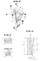
- Fig. 2 is a perspective view of an embodiment of a side wall in accordance with the invention for use in the belt caster of Fig. 1;
- Figs. 3 and 4 are respectively sections taken along lines A - A and B - B of Fig. 2;
- Fig. 5 is a section taken along line C - C of Fig. 2;
- Fig. 6 is a vertical section through a second embodiment of a side wall in accordance with the invention for use in the belt caster of Fig. 1;
- Fig. 7 is a section taken along line D - D of Fig. 6;
- Fig. 8 is a diagrammatic front view of the side wall of Fig. 6;
- Fig. 9 is a graph showing the relationship between refractory damage and the casting length;
- Fig. 10 is a section through a part of an embodiment of a side wall according to the invention; and
- Fig. 11 is a graph showing variation of side wall surface temperature with the duration of casting.
- Referring now to the drawings, particularly to Fig. 1, the general construction of a continuous belt caster, for which the side wall according to the present invention is applicable, will be discussed briefly in order to facilitate better understanding of the invention. As shown in Fig. 1, the belt caster includes a pair of metallic
endless belts 1 and 2 forming the moving walls of the caster, and a pair ofside walls endless belts 1 and 2 is associated withguide rollers 3a, 3b and 3c, one of which is drivingly connected to a driving device to be rotatingly driven for circulating the belt. The portion of the belt extending between the guide rollers 3a and 3c forms the moving wall of the caster and is associated with acooling pad 7a or 7b, to which coolant, such as cooling water, is circulated for cooling the associated one of the belts, 1 or 2. - As can be seen from Fig. 1, the
side walls side walls belts 1 and 2 and theside walls nozzle 6. - As can be seen from Figs. 1 and 2, the
side walls metallic walls 8. - Each
metal wall 8 is formed with an essentiallytriangular recess 8a defined by frame-like edge portions 9. Arefractory layer 10 is disposed within therecess 8a to complete the side wall assembly. - In the casting chamber, the melt is cooled by heat exchange with the
belts 1 and 2 and thus gradually grows a solidified shell on the belts. Also, the portion of the melt interfacing with theedge portions 9 of theside walls side walls - As shown in Figs. 3 and 4, the
metallic wall 8 of theside wall refractory layer 10 is enclosed by therecess 8a. Therefractory layer 10 has an essentially triangular cross section and has a peak X located at the transverse center of therefractory layer 10 and projecting into the casting chamber. The extent to which peak X projects into the chamber is greatest at the inlet end and gradually decreases to zero towards the outlet end. - As particularly shown in Fig. 5, by gradually decreasing the extent to which the peak X projects into the chamber in the above manner, the profile of the refractory layer has a positive taper with a gradient of δ₁/ ℓ₁, where δ₁ is the peak height difference between the inlet end and the outlet end of the refractory layer and ℓ₁ is length of the peak. On the other hand, the thickness of the
edge portion 9 of themetal wall 8 gradually increases towards the outlet end. The gradient of theedge portion 9 is δ₂/ ℓ₂, where δ₂ is the difference between the thickness ofedge portion 9 at the inlet end and the thickness of the edge portion at the outlet end, and ℓ₂ is the overall length of the side wall. - Because the
metallic wall 8 is cooled by coolant circulating inside the coolant passage, heat exchange occurs between the melt and theedge portions 9 which define a portion of the inside surface of the chamber, thereby cooling the melt. Consequently, a solidified shell is grown on theedge portions 9. During the continuous casting operation, the solidified shell is released from the surface of the exposed surfaces of theside walls edge portions 9. - In order to demonstrate the performance of a belt caster employing the illustrated embodiment of side walls according to the present invention, an experiment was performed for casting a low carbon aluminium killed steel cast block having a thickness of 30 mm and a width of 1200 mm. The casting speed was 12 m/min. The
refractory layer 10 was formed of silica brick. The relevant dimensions δ₁, δ₂, ℓ₁ and ℓ₂ were as follows:
δ₁ = 35 mm
δ₂ = 12 mm
ℓ₁ = 65 cm
ℓ₂ = 100 cm - Under the conditions described above, continuous casting for 600 m per heat was performed.
- The casting operation was performed very smoothly without causing break out or defects in the cast block.
- An alternative embodiment is shown in Figs. 6 and 7 where the
refractory layer 10 supported in themetallic wall 8 comprises a heat insulativerefractory layer 10a and a wear-resistant refractory layer 10b. In the shown embodiment, a coolant passage 11a extending through the major section of themetallic wall 8, and a coolant passage 11b extending through theedge portions 9 of the wall are provided. As can be seen from Figs. 6 and 7, the heat insulativerefractory layer 10a is an inner layer located adjacent to themetallic wall 8 and the wear-resistant refractory layer 10b is an outer layer which comes into contact with the melt in the chamber. In addition, a sectionheat insulative layer 10c is at least partially formed on the surface of the wear-resistant layer 10b. As can be seen from Fig. 8, theheat insulative layer 10c is formed in an area starting immediately below the meniscus line M and terminating at the portion where a constant width section starts at the outlet side. - Preferably, the heat insulative
refractory layer 10a is selected from a material having a heat transfer rate lower than or equal to 0.002 cal/cm.s.°C. For example, MgO board, SiO₂ type board, molten silica brick may be selected for forming the heat insulative refractory layer. On the other hand, the material for forming theheat insulative layer 10c is preferably selected from, for example, asbestos wool, glass fiber fabrics, rock wools. The preferred thickness of theheat insulative layer 10c to be formed on the wear-resistant refractory layer 10b is in a range of 1 mm to 3 mm. When the thickness of theheat insulative layer 10c is less than 1 mm heat insulation becomes insufficient. On the other hand, if the thickness of theheat insulative layer 10c becomes thicker than 3 mm the amount of slag created by melting becomes substantial. Furthermore, the material of the wear-resistant refractory layer preferably has a high spalling resistance and mechanical strength, particularly as the shore hardness of the cast block immediately after withdrawal from the casting chamber is less than or equal to 10. Therefore, the wear-resistant refractory layer should have a shore hardness greater than or equal to 10. Preferably, the material for the wear-resistant refractory layer is selected to have a shore hardness greater than or equal to 15 at a temperature of 1200°C. Materials satisfying this condition include; silicon nitride, sialon, alumina, mullite, zirconium boride or compositions of the above-mentioned material and boron-nitride. - In the preferred construction, the thickness of the wear-resistant refractory layer 10b is in a range of 2 mm to 10 mm. If the thickness of the wear-resistant refractory layer is less than 2 mm, it is easy to break thus making handling difficult. Furthermore, such thin layers may not have satisfactory resistance against heat shock and thus may break when subjected to heat shock. On the other hand, when the thickness of the wear-resistant refractory layer 10b is thicker than 10 mm, heat absorption at the initial stage of casting becomes substantial and causes the formation of solidified shell thereon.
- In order to demonstrate the performance of the belt caster employing the illustrated embodiment of the side walls according to the present invention, an experiment was performed for casting a low carbon aluminum killed steel cast block having a thickness of 25 mm and a width of 1350 mm. The casting speed was 12 m/min. The
metallic wall 8 was formed of Cu material containing Ag. The heat insulativerefractory layer 10a was formed of MgO board with a thickness 15 mm. On the other hand, the wear-resistant refractory layer 10b was formed of sialon containing 20% BN. The properties of these refractory layers are shown in the following table:
- In order to compare with the example described above, comparative experiments were performed with single refractory layers formed of sialon-BN and SiO₂ type material. The results of experimental casting according to the present invention and the comparative examples are shown in Fig. 9.
- In the case of the SiO₂ single layer refractory, the thickness of melting out of the refractory was approximately 1 mm for a casting length of 300 m. In this comparative example, break out was observed. On the other hand, in the case of the sialon-BN single layer refractory, the force required for withdrawing the cast block was increased at the initial stage of casting. After casting a length of 6 m, break out was observed. In contrast, casting was smoothly performed without causing melting of the refractory when the MgO/Sialon/BN refractory material was used.
- An additional experiment was performed in which asbestos fabric 2.0 mm thick was attached to the wear-resistant layer in the manner shown in Fig. 8. A low carbon aluminium killed steel cast block having a thickness of 25 mm and a width of 1350 mm was cast. The casting speed was 12 m/min. The temperature of the melt supplied to the casting chamber was 1,568°C. The temperature of the wear-resistant refractory layer was measured by means of a
thermocouple 12 embedded at a position 1.5 mm from the surface, as shown in Fig. 10. The temperature measured by thethermocouple 12 is shown in Fig. 11. In Fig. 11, line A shows the temperature variation in the wear-resistant refractory layer when the asbestos layer was not attached and line B shows the temperature variation in the wear-resistant refractory layer when coupled with the asbestos layer. As can be seen from Fig. 11, the temperature in both cases become substantially equal to one another 14 seconds after starting the casting operation. In the case when there is an asbestos layer, the heat insulative effect of the asbestos layer resulted in no formation of a solidified shell, even during the low temperature period, i.e. within approximately 9 sec. of starting the casting operation. In contrast, in the case when there was no asbestos layer, slight solidification was observed in the period up to 5 sec. after the start of casting. - While the present invention has been disclosed in terms of the preferred embodiment in order to facilitate better understanding of the invention, it should be appreciated that the invention can be embodied in various ways without departing from the principle of the invention. Therefore, the invention should be understood to include all possible embodiments and modifications to the shown embodiments which can be realised without departing from the principle of the invention as set out in the appended claims.
- For example, though the shown embodiments are concerned with a belt caster, the present invention is applicable to any type of continuous caster which employs a side wall having a refractory layer.
Claims (11)
- A side wall for a continuous caster of the type comprising a pair of endless circulating bodies (1,2) forming moving walls of the caster and a pair of side walls (4,5) forming stationary walls of said caster wherein the stationary walls are cooperative with said moving walls for defining the interior surface of a casting chamber to which molten metal is introduced for the purpose of casting a continuous cast block, said side wall comprising:a) metallic wall (8), andb) a refractory layer (10)(10a)(10b)(10c) located on the interior surface of the metallic wall so as to partially define the inside surface of the chamber and come into contact with molten metal in the chamber, the refractory layer being partially enclosed in a recess (8a) in the metallic wall edge portions (9) of the metallic walls which extend beyond the refractory layer and define a portion of the inside surface of the chamber and come into contact with molten metal in the chamber characterised in that the refractory layer has an essentially triangular cross-section with a peak (X) located so as to project into the chamber the extent to which the peak projects into the chamber diminishing in the throughput direction.
- A side wall as claimed in claim 1 wherein the peak of the triangular cross-section is rounded.
- A side wall as claimed in claim 1 or 2 wherein the peak of said triangular cross-section is central with respect to the side walls.
- A side wall as claimed in any preceding claim wherein said refractory layer comprises an inner heat-insulating refractory layer (10a) and an outer wear-resistant refractory layer (10b) which has a surface which partially defines the inside surface of the chamber.
- A side wall as claimed in claim 4 which further comprises a second heat- insulating layer (10c) formed on the surface of said wear-resistant refractory layer.
- A side wall as claimed in claim 5 wherein said second heat-insulating layer is provided in a region below the meniscus (M) of the molten metal.
- A side wall as claimed in any of claims 4 to 6 wherein said second heat-insulating layer is formed of a material selected from; asbestos fabric, glass fibre fabric or rock wool.
- A side wall as claimed in any of claims 4 to 7 wherein said wear-resistant refractory layer is formed of a material having a shore hardness, within a predetermined high temperature range, greater than the shore hardness of the cast block immediately after casting.
- A side wall as claimed in any of claims 4 to 8 wherein the material of the wear-resistant refractory layer has a shore hardness of at least 15 at 1200°C.
- A side wall as claimed in any of claims 4 to 9 wherein said wear-resistant refractory layer is formed of a material selected from; silicon nitride, sialon, alumina, mullite and zirconium boride or a combination of any one of these and boron nitride.
- A side wall as claimed in any of claims 4 to 10 wherein said heat-insulating refractory layer is formed of a material selected from; MgO board, SiO₂ type board or molten silica brick.
Applications Claiming Priority (4)
| Application Number | Priority Date | Filing Date | Title |
|---|---|---|---|
| JP15504688A JPH01321047A (en) | 1988-06-24 | 1988-06-24 | Short side plate of continuous thin slab casting machine |
| JP155046/88 | 1988-06-24 | ||
| JP29804688A JPH02147151A (en) | 1988-11-28 | 1988-11-28 | Short side plate of continuous thin slab casting machine |
| JP298046/88 | 1988-11-28 |
Publications (2)
| Publication Number | Publication Date |
|---|---|
| EP0348227A1 EP0348227A1 (en) | 1989-12-27 |
| EP0348227B1 true EP0348227B1 (en) | 1993-05-05 |
Family
ID=26483154
Family Applications (1)
| Application Number | Title | Priority Date | Filing Date |
|---|---|---|---|
| EP89306400A Expired - Lifetime EP0348227B1 (en) | 1988-06-24 | 1989-06-23 | Side wall construction for continuous belt caster |
Country Status (3)
| Country | Link |
|---|---|
| US (1) | US5127462A (en) |
| EP (1) | EP0348227B1 (en) |
| DE (1) | DE68906312T2 (en) |
Cited By (1)
| Publication number | Priority date | Publication date | Assignee | Title |
|---|---|---|---|---|
| DE4337399A1 (en) * | 1993-10-26 | 1995-04-27 | Mannesmann Ag | Continuous casting mould for the production of thin slabs, plates or sheets of steel |
Families Citing this family (4)
| Publication number | Priority date | Publication date | Assignee | Title |
|---|---|---|---|---|
| FR2666256B1 (en) * | 1990-09-03 | 1992-10-16 | Usinor Sacilor | CONTINUOUS CASTING INSTALLATION BETWEEN CYLINDERS. |
| FR2699436A1 (en) * | 1992-12-17 | 1994-06-24 | Usinor Sacilor | Device for the continuous casting of metal between rolls |
| FR2765504B1 (en) * | 1997-07-04 | 1999-08-20 | Usinor | SIDE SIDE FOR SEALING THE CASTING SPACE OF A CONTINUOUS CASTING INSTALLATION BETWEEN METAL THIN STRIP CYLINDERS |
| KR100431832B1 (en) * | 1999-08-26 | 2004-05-20 | 주식회사 포스코 | An Edge Dam For Twin Roll Type Strip Caster |
Family Cites Families (5)
| Publication number | Priority date | Publication date | Assignee | Title |
|---|---|---|---|---|
| JPS5838640A (en) * | 1981-08-31 | 1983-03-07 | Kawasaki Steel Corp | Continuous casting device for thin metal sheet |
| JPS609553A (en) * | 1983-06-29 | 1985-01-18 | Kawasaki Steel Corp | Stopping down type continuous casting machine |
| JPS6343744A (en) * | 1986-08-11 | 1988-02-24 | Kawasaki Steel Corp | Short side mold for continuous casting of thin slabs |
| JPS63149044A (en) * | 1986-12-12 | 1988-06-21 | Kawasaki Steel Corp | Short side plate of continuous thin slab casting machine |
| FR2613646B1 (en) * | 1987-04-09 | 1991-02-01 | Siderurgie Fse Inst Rech | SIDE SHUTTERING DEVICE FOR CONTINUOUS CASTING LINGOTIERE BETWEEN CYLINDERS |
-
1989
- 1989-06-23 DE DE8989306400T patent/DE68906312T2/en not_active Expired - Fee Related
- 1989-06-23 EP EP89306400A patent/EP0348227B1/en not_active Expired - Lifetime
-
1991
- 1991-05-21 US US07/704,895 patent/US5127462A/en not_active Expired - Fee Related
Cited By (1)
| Publication number | Priority date | Publication date | Assignee | Title |
|---|---|---|---|---|
| DE4337399A1 (en) * | 1993-10-26 | 1995-04-27 | Mannesmann Ag | Continuous casting mould for the production of thin slabs, plates or sheets of steel |
Also Published As
| Publication number | Publication date |
|---|---|
| DE68906312D1 (en) | 1993-06-09 |
| EP0348227A1 (en) | 1989-12-27 |
| US5127462A (en) | 1992-07-07 |
| DE68906312T2 (en) | 1993-08-12 |
Similar Documents
| Publication | Publication Date | Title |
|---|---|---|
| CA1139529A (en) | Method for continuous casting of metallic strands at exceptionally high speeds | |
| KR100607428B1 (en) | Casting molds for the production of cooling elements and cooling elements produced therefrom | |
| US4911226A (en) | Method and apparatus for continuously casting strip steel | |
| EP0348227A1 (en) | Side wall construction for continuous belt caster | |
| EP0448773B1 (en) | Continuous caster mold and continuous casting process | |
| CA1325875C (en) | Side wall construction for continuous belt caster | |
| AU738253B2 (en) | Tapping launder for a molten iron | |
| US6173755B1 (en) | Nozzle for continuous slab casting | |
| JP2005536352A (en) | Side face of a plant used for twin-roll continuous casting of metal strips | |
| US20050280192A1 (en) | Zirconia refractories for making steel | |
| JPH01228645A (en) | Method for preventing longitudinal crack on solidified shell surface in continuous casting mold | |
| JP3289118B2 (en) | Shrinkage hole reduction device in continuous casting | |
| US5092391A (en) | Device for the continuous casting of thin metal products between rolls | |
| CA1240819A (en) | Apparatus for closing off the sides of a shaping cavity of substantially rectangular cross-section in a continuous casting installation | |
| KR20010040757A (en) | Device for continuous casting in vertical charge of a melting metal | |
| JPH01170551A (en) | Mold for continuously casting steel | |
| JPH10193042A (en) | Mold for continuous casting of molten steel | |
| JPH04197555A (en) | Mold for horizontal continuous casting having excellent wear resistance | |
| KR100922068B1 (en) | Nozzle Blocking Device | |
| KR20110120544A (en) | Ladle bubbling cone drawing jig and drawing method using the same | |
| JPH0438503B2 (en) | ||
| JPH0275450A (en) | Side plate at short side in thin ingot continuous casting machine | |
| JP2558187B2 (en) | Heating mold for continuous casting | |
| JPS58218349A (en) | Stationary side plate of continuous casting device of thin steel plate | |
| JPH07106428B2 (en) | Mold for continuous casting of metal |
Legal Events
| Date | Code | Title | Description |
|---|---|---|---|
| PUAI | Public reference made under article 153(3) epc to a published international application that has entered the european phase |
Free format text: ORIGINAL CODE: 0009012 |
|
| AK | Designated contracting states |
Kind code of ref document: A1 Designated state(s): DE FR GB IT |
|
| 17P | Request for examination filed |
Effective date: 19900221 |
|
| 17Q | First examination report despatched |
Effective date: 19910826 |
|
| GRAA | (expected) grant |
Free format text: ORIGINAL CODE: 0009210 |
|
| AK | Designated contracting states |
Kind code of ref document: B1 Designated state(s): DE FR GB IT |
|
| ITF | It: translation for a ep patent filed | ||
| REF | Corresponds to: |
Ref document number: 68906312 Country of ref document: DE Date of ref document: 19930609 |
|
| ET | Fr: translation filed | ||
| PLBE | No opposition filed within time limit |
Free format text: ORIGINAL CODE: 0009261 |
|
| STAA | Information on the status of an ep patent application or granted ep patent |
Free format text: STATUS: NO OPPOSITION FILED WITHIN TIME LIMIT |
|
| 26N | No opposition filed | ||
| PGFP | Annual fee paid to national office [announced via postgrant information from national office to epo] |
Ref country code: FR Payment date: 19990610 Year of fee payment: 11 |
|
| PGFP | Annual fee paid to national office [announced via postgrant information from national office to epo] |
Ref country code: GB Payment date: 19990623 Year of fee payment: 11 |
|
| PGFP | Annual fee paid to national office [announced via postgrant information from national office to epo] |
Ref country code: DE Payment date: 19990626 Year of fee payment: 11 |
|
| PG25 | Lapsed in a contracting state [announced via postgrant information from national office to epo] |
Ref country code: GB Free format text: LAPSE BECAUSE OF NON-PAYMENT OF DUE FEES Effective date: 20000623 |
|
| GBPC | Gb: european patent ceased through non-payment of renewal fee |
Effective date: 20000623 |
|
| PG25 | Lapsed in a contracting state [announced via postgrant information from national office to epo] |
Ref country code: FR Free format text: LAPSE BECAUSE OF NON-PAYMENT OF DUE FEES Effective date: 20010228 |
|
| REG | Reference to a national code |
Ref country code: FR Ref legal event code: ST |
|
| PG25 | Lapsed in a contracting state [announced via postgrant information from national office to epo] |
Ref country code: DE Free format text: LAPSE BECAUSE OF NON-PAYMENT OF DUE FEES Effective date: 20010403 |
|
| PG25 | Lapsed in a contracting state [announced via postgrant information from national office to epo] |
Ref country code: IT Free format text: LAPSE BECAUSE OF NON-PAYMENT OF DUE FEES;WARNING: LAPSES OF ITALIAN PATENTS WITH EFFECTIVE DATE BEFORE 2007 MAY HAVE OCCURRED AT ANY TIME BEFORE 2007. THE CORRECT EFFECTIVE DATE MAY BE DIFFERENT FROM THE ONE RECORDED. Effective date: 20050623 |